
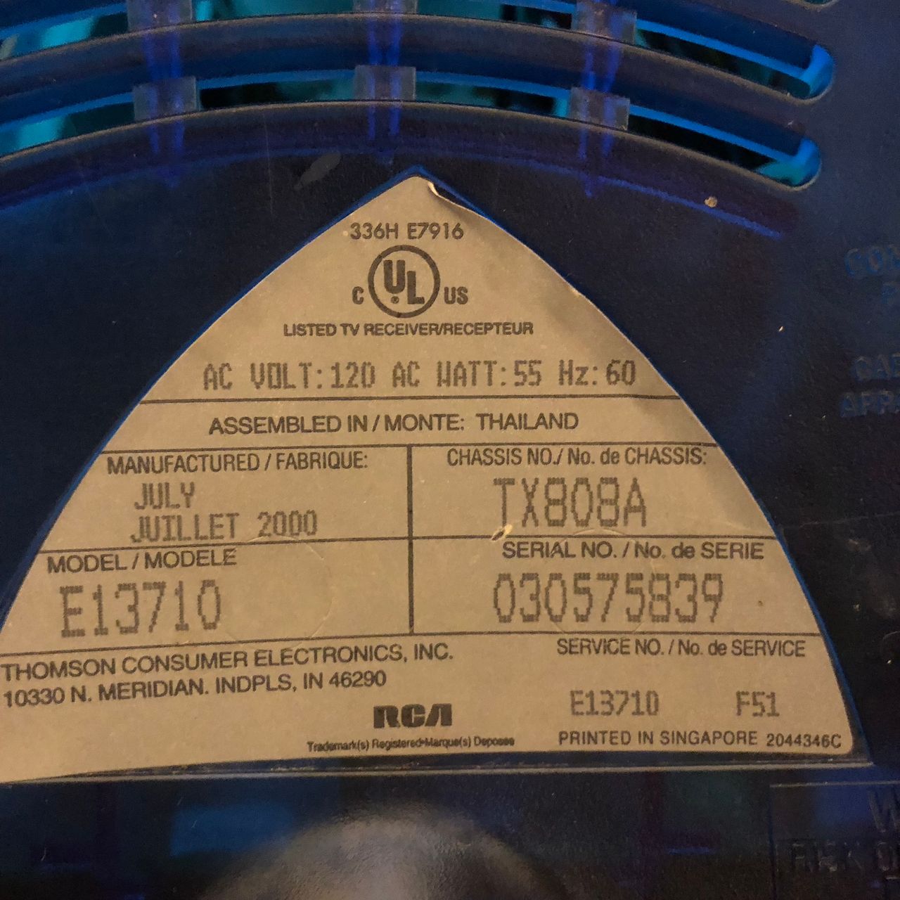
RCA E13710
RCA E13710 CRT RGB mod
The RCA E13710 is a 13" CRT television from the early 2000s. It is frequently used for RGB modding to achieve superior image quality.
Some of these sets are coax/RF only, and require firmware flashing prior to modifying for RGB.
View full CRT details and more mod examples →
The same tutorial should also work for the below model.
- RCA E13318 (firmware flashing not needed)
- RCA E13309 (firmware flashing needed)
- RCA E13710 (firmware flashing needed)
Contributors
Thank you to everyone who contributed to this guide:
- Kaz Packman — contributor, RGB mod tutorial
CRT safety
Caution
You can die doing this! So read carefully! CRT TV is not a toy. Do not open a CRT TV. If you don't have any prior knowledge about handling high voltage devices, this guide is not for you. CRT TV contains high enough voltage (20,000+ V) and current to be deadly, even when it is turned off.
Plan of attack
Manuals and Datasheets
Specs
- Year:
- Screen Size: 13"
Performing the mod
- RCA E13318 (firmware flashing not needed)
- RCA E13309 (firmware flashing needed)
- RCA E13710 (firmware flashing needed)
Flashing the firmware
Since the RCA is RF-only (but not a hot chassis luckily), I had to flash the firmware with one from a model with AV inputs to activate the AV input feature so I can tap into that for sync and audio.
I removed the EEPROM chip (the tiny 8-pin DIP chip near the Microcontroller) and flashed an equivalent chip using a CH341A USB programmer and the firmware for an E13318 model that I found online. It worked, although as expected the settings for the TV changed as those are held within the chip I replaced. The main thing I had to change was the language setting as it was set to Spanish on the new EEPROM by the original owner of the set it came from. The user manual should mention how to change it back to English.
Some users reported that the language setting doesn't change with the new firmware, so the best way to make sure the new firmware is functioning is by checking to see if the "VID" channel is available using the channel up/down buttons on the set. If you can access the "VID" channel, then the firmware has been successfully flashed.
Download the firmware file if you have an EEPROM programmer to flash on your set.
Tips
The firmware shouldn’t need to be flashed on the E13318 as it already has an AV input.
Performing the mod
Now that you roughly know what needs to be done, prepare for the mod. Place the board on a comfortable place. Make sure you are not putting pressure on the flyback or other components.
STEP 1: Remove the following components
Remove the following RGB resistors that are connected to the ground.
- RR535
- RR536
- RR537
STEP 2: Connect RGBs, Blanking and Audio
Picture below shows where the RGB and blanking wires should be soldered.
![]()
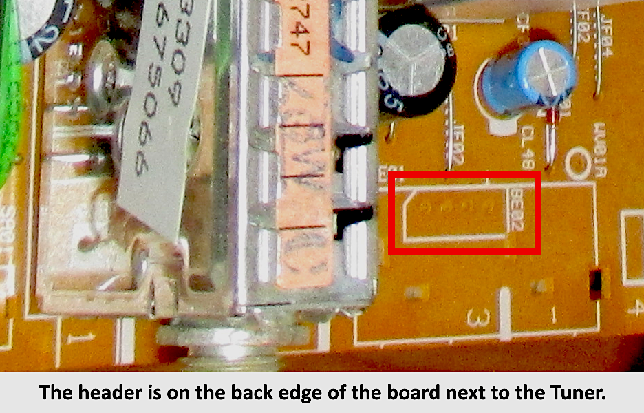
Picture below shows the BE01 header where the Composite Sync, Audio and Ground wires should be connected.
STEP 3: Build your mux board/circuit
Below mod uses the RGB mux board. This is optional, but will make your mod easier and stable. You can also create the circuit presented in the schematics above without the board.
| TV Model | E13710 |
|---|---|
| Audio LR (R7, R8) | 1kΩ |
| RGB termination (R1, R2, R3) | 180Ω |
| RGB inline resistors (R4, R5, R6) | 820Ω |
| Diode (R9) | 1N4148 |
| Blanking Resistor (R11) | shorted |
STEP 4: Attach the female SCART connector to TV
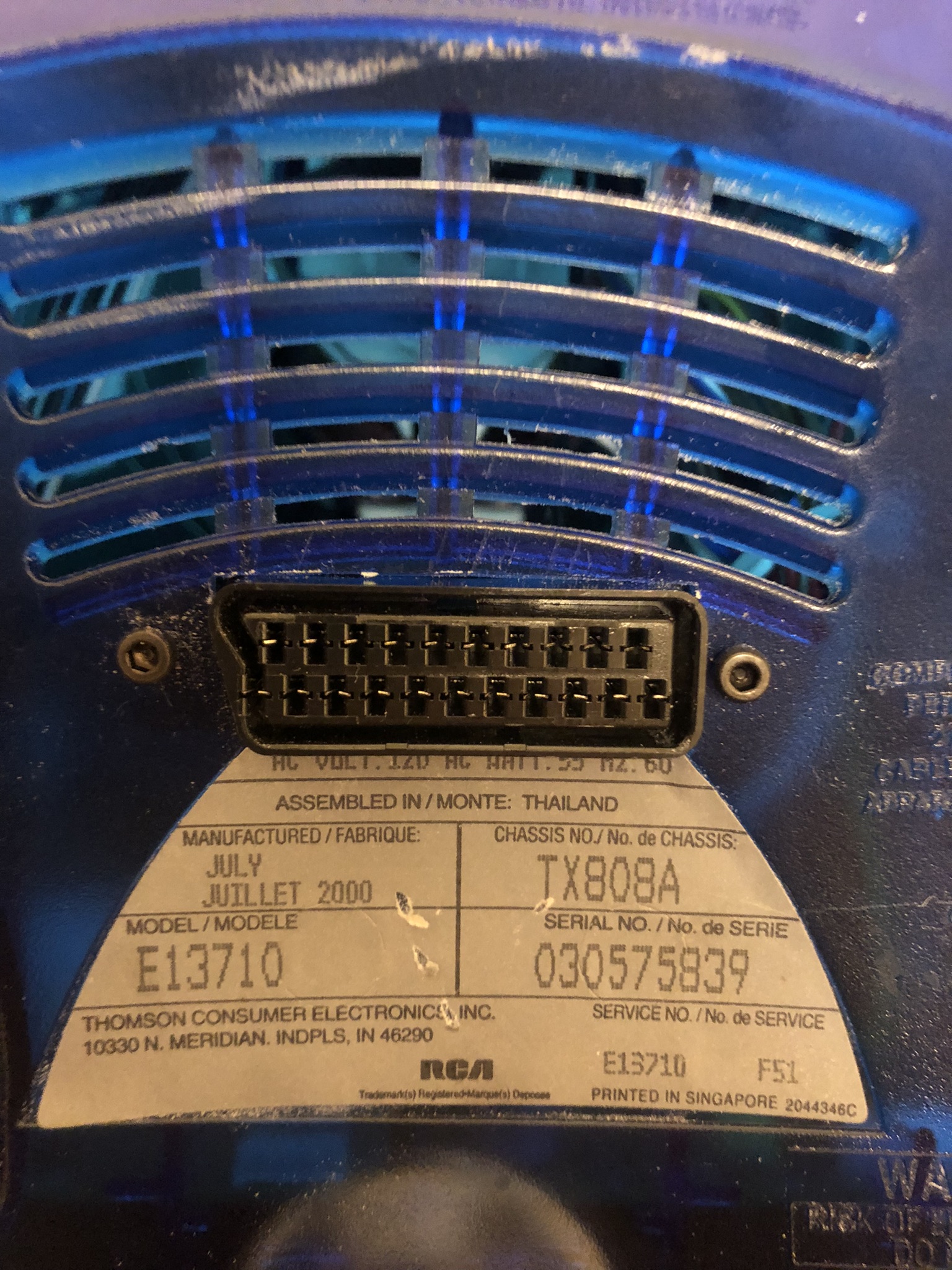
Creating a SCART cutout and mounting it is an art. I have a dedicated section for it.
How to create and mount a SCART female plug?
Pictures of the mod
Games
SNES - Super Mario World 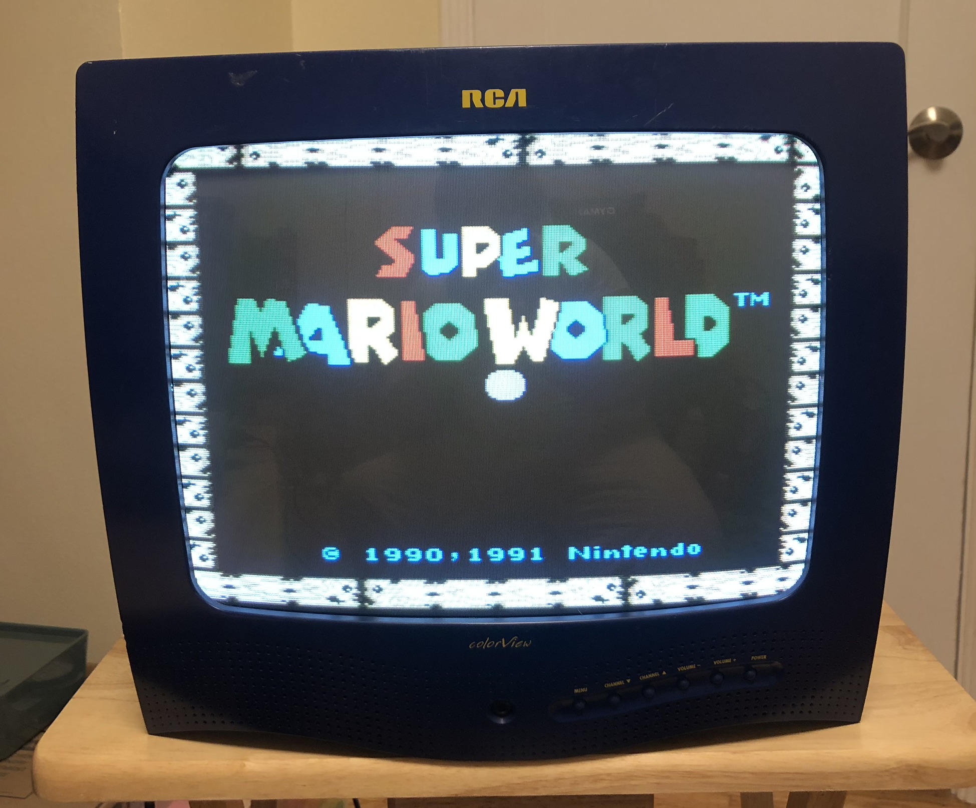
SNES - Dr. Mario 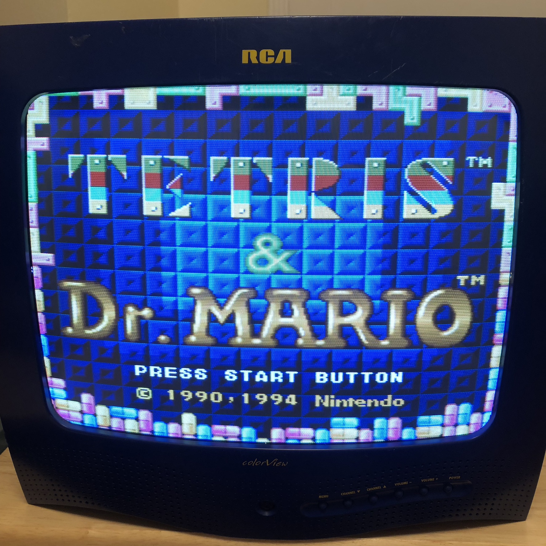
PSOne Slim 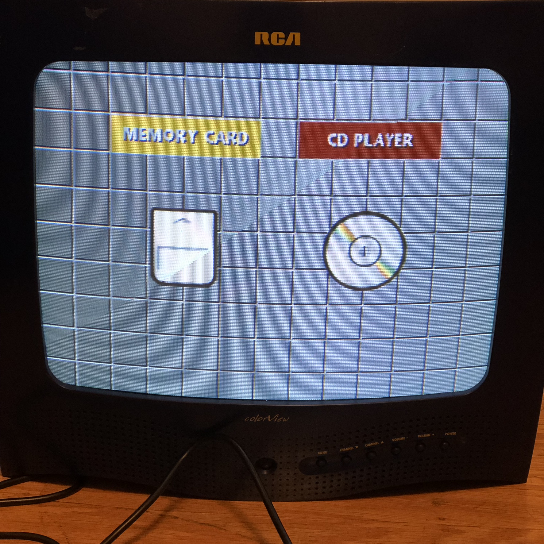
SNES - Tetris 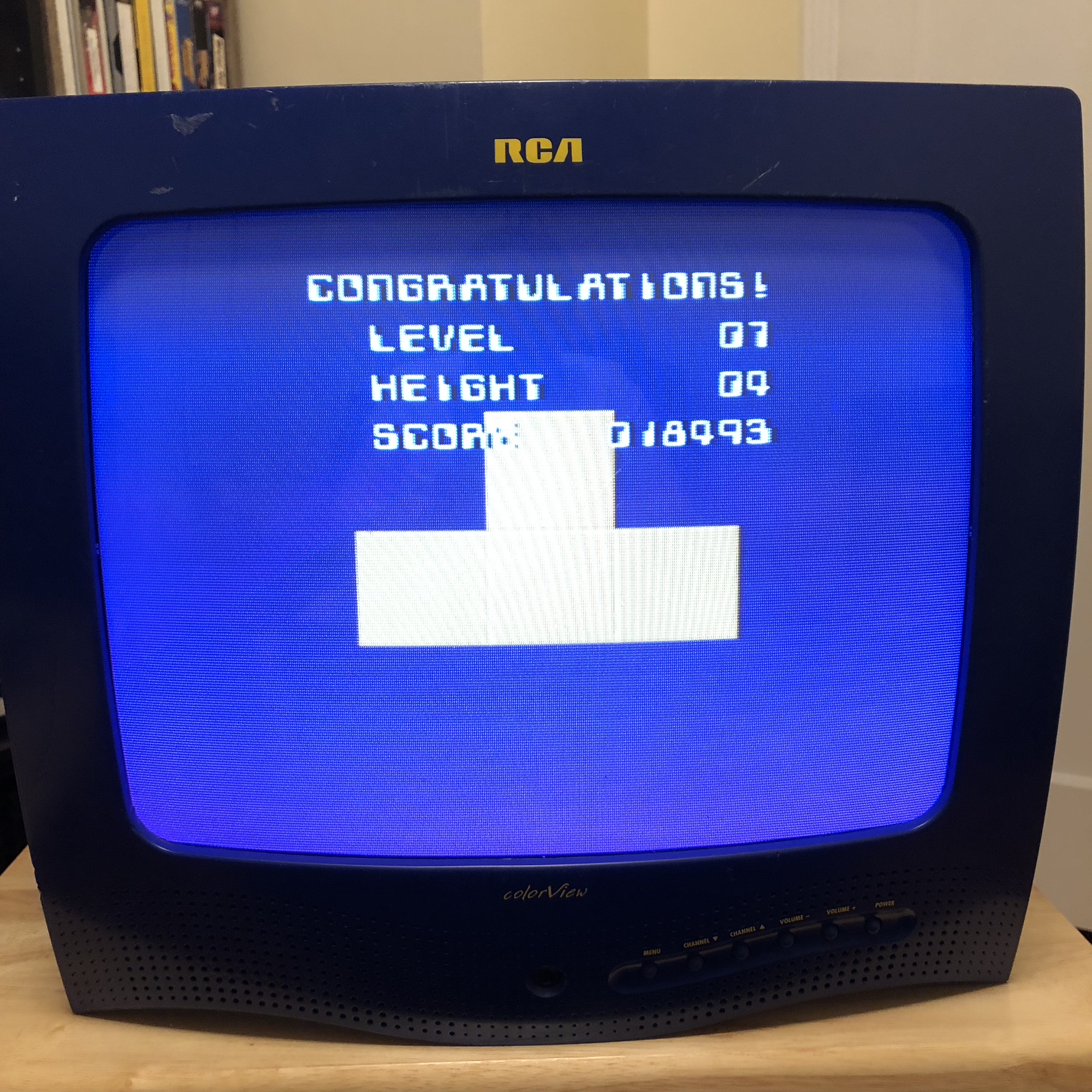
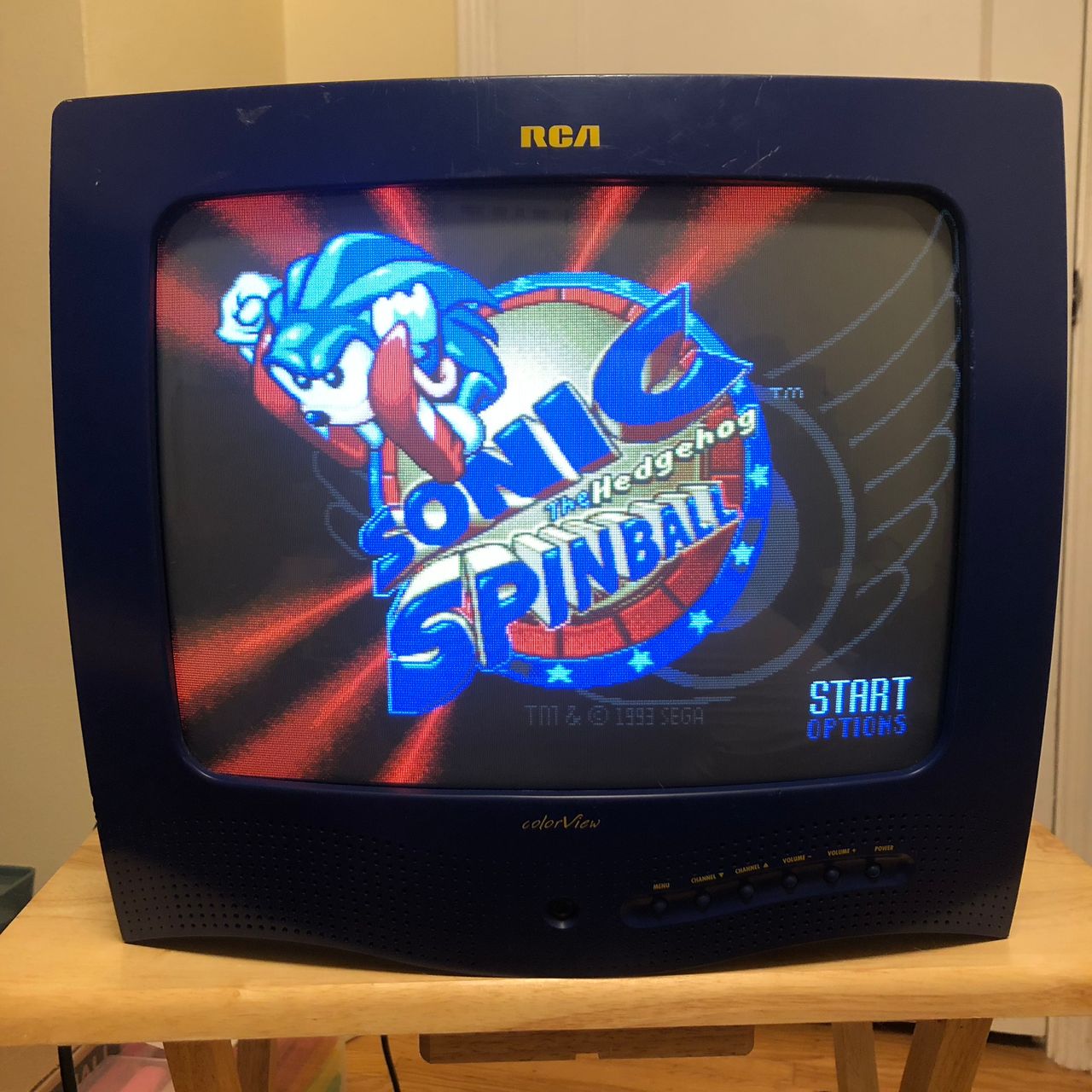
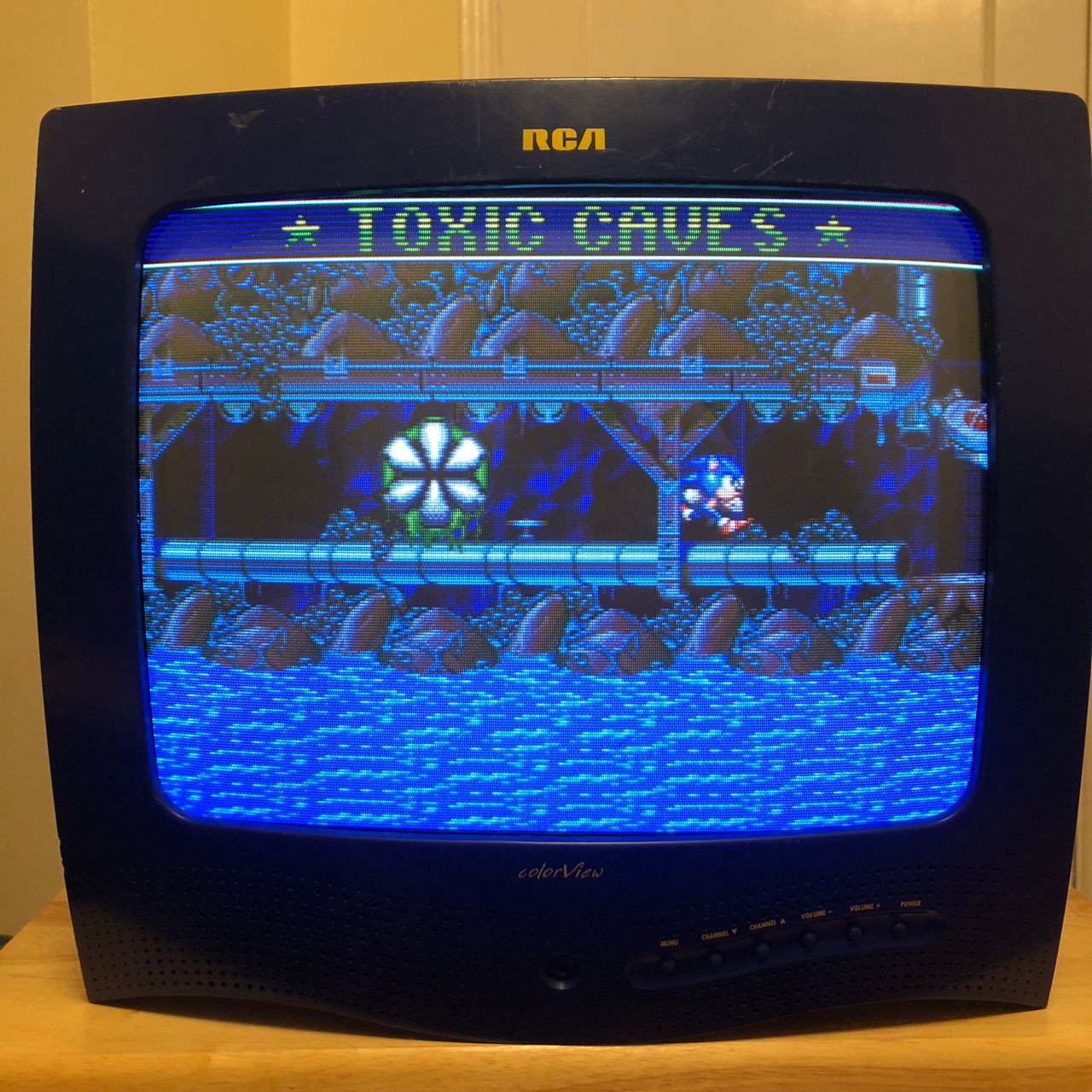
Sega Genesis - Sonic Spinball 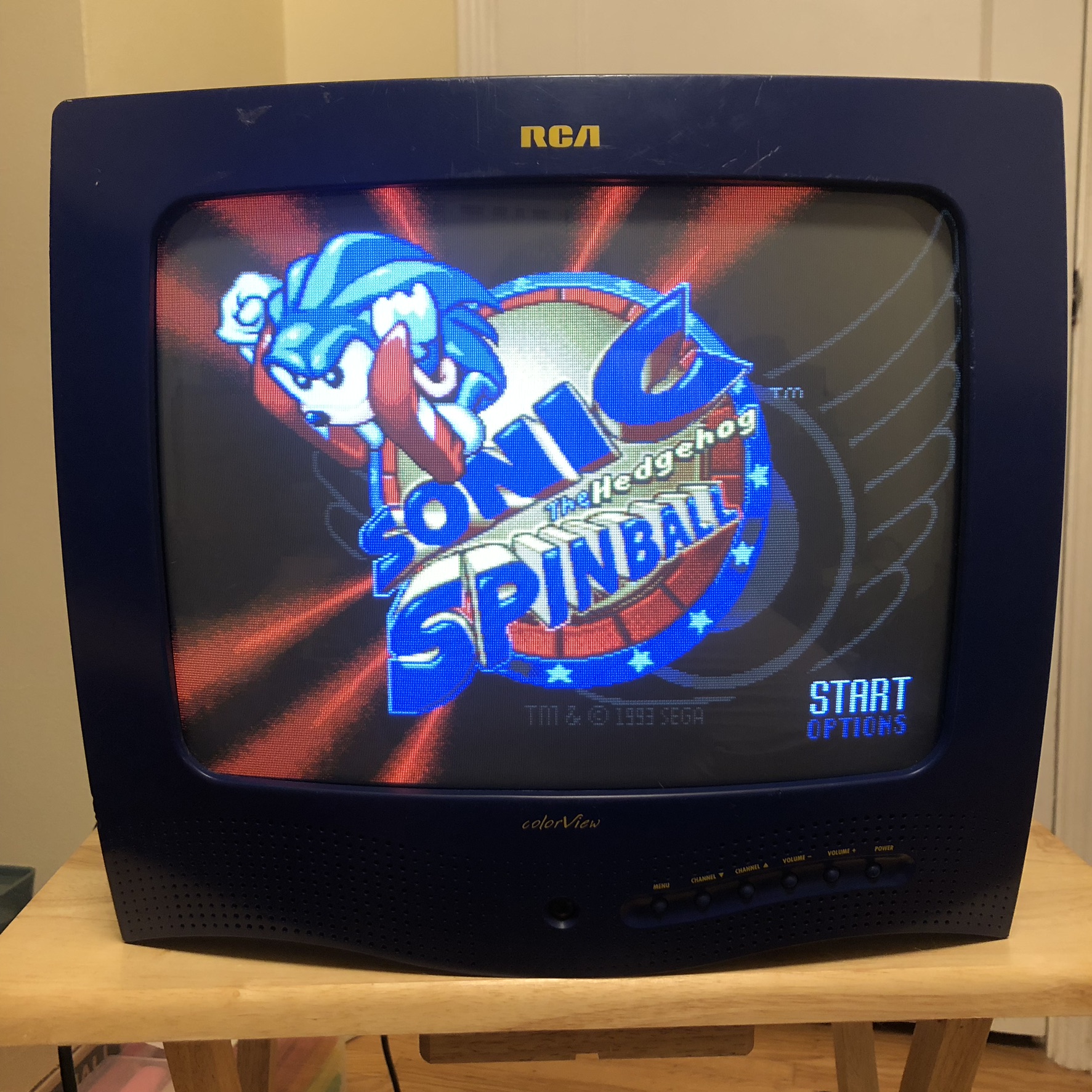
Sega Genesis - Sonic Spinball 
Pictures
Reference Photos

See more photos and contributions →
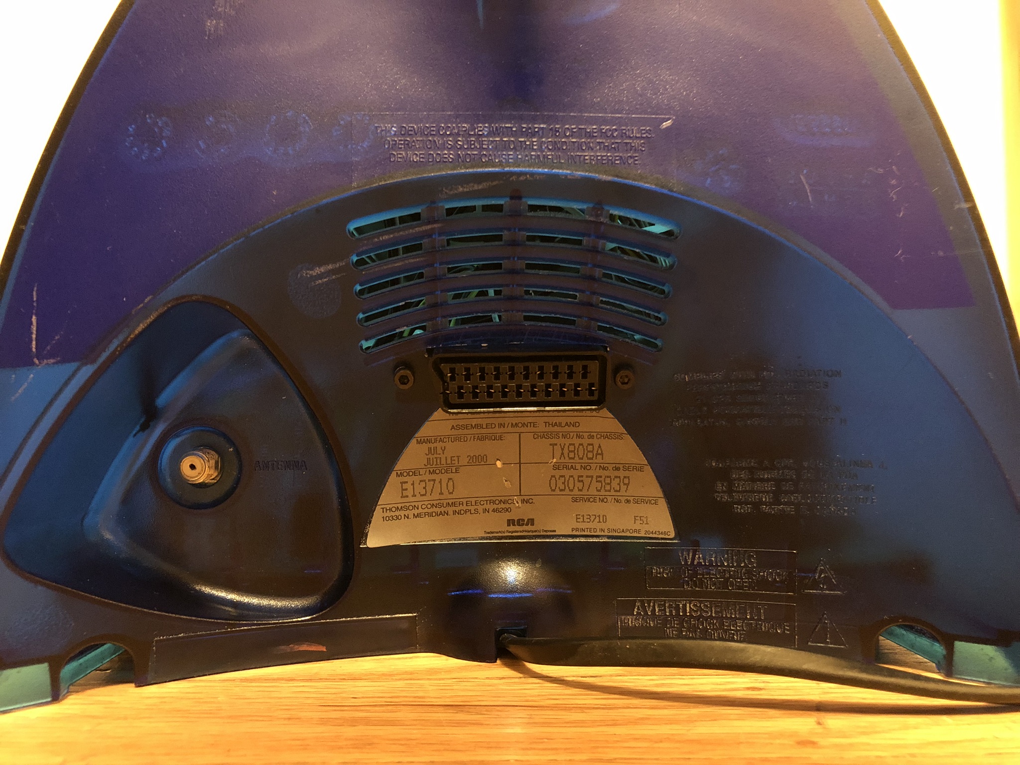
Casing RCA E13710
Front 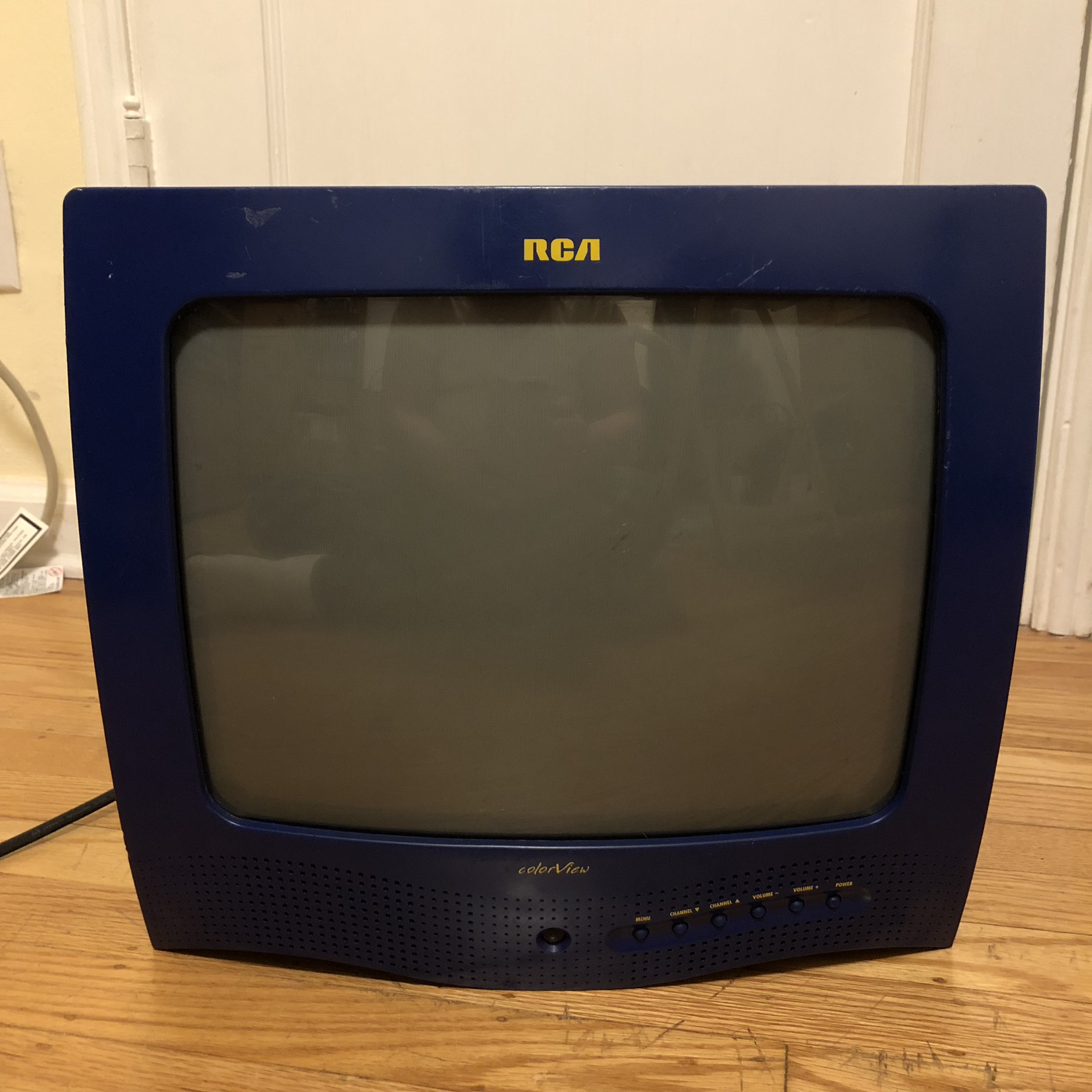
Back
Right 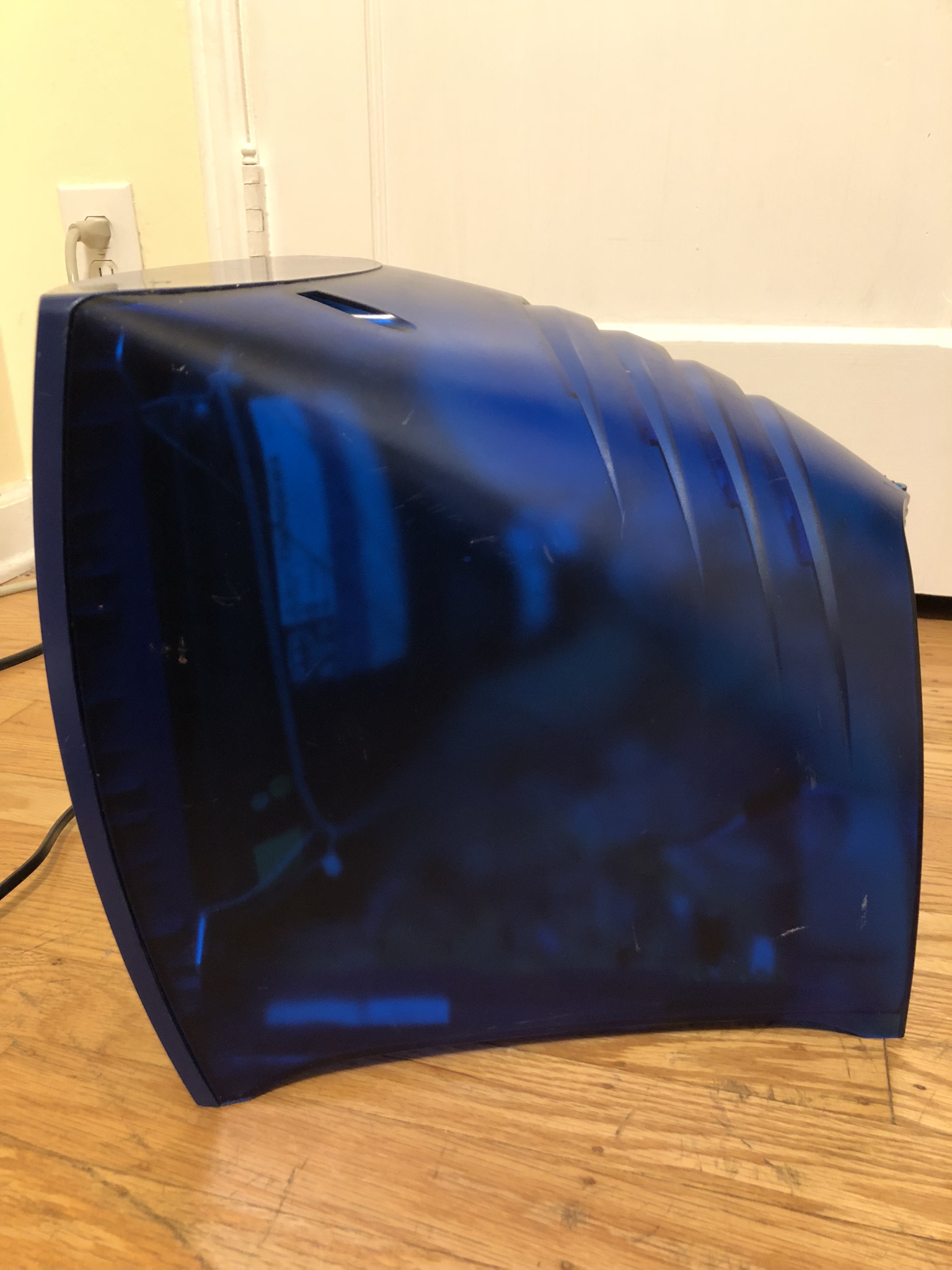
Left ![]()