Toshiba CF19G32
Toshiba CF19G32 CRT RGB mod
The Toshiba CF19G32 is a 19" consumer CRT known for its high-quality picture tube and suitability for RGB modification.
View full CRT details and more mod examples →
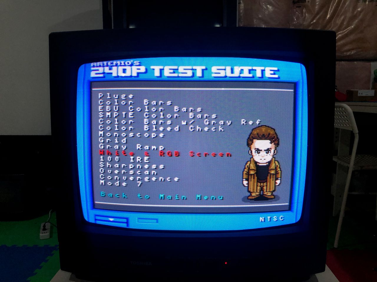
 Captured from RGB modded NES
Contributors
Thank you to everyone who contributed to this guide:
- Sunthar — author
CRT safety
Caution
You can die doing this! So read carefully! CRT TV is not a toy. Do not open a CRT TV. If you don't have any prior knowledge about handling high voltage devices, this guide is not for you. CRT TV contains high enough voltage (20,000+ V) and current to be deadly, even when it is turned off.
Plan of attack
Manuals and Datasheets
Specs
- Manufactured: Thailand (2001)
- Format: NTSC
- Tube: Toshiba A48KZL70X
- Jungle Chip: Toshiba TA1223AN
- OSD Chip: Toshiba TMP87CM34BN
- Screen Size: 13"
- Weight: 22 lbs
- Inputs: Composite, RF
Schematics
Get hold of the schematics for your TV. Understand where the RGB and Fast Blanking signals go from OSD to the Jungle (Chroma) chip.
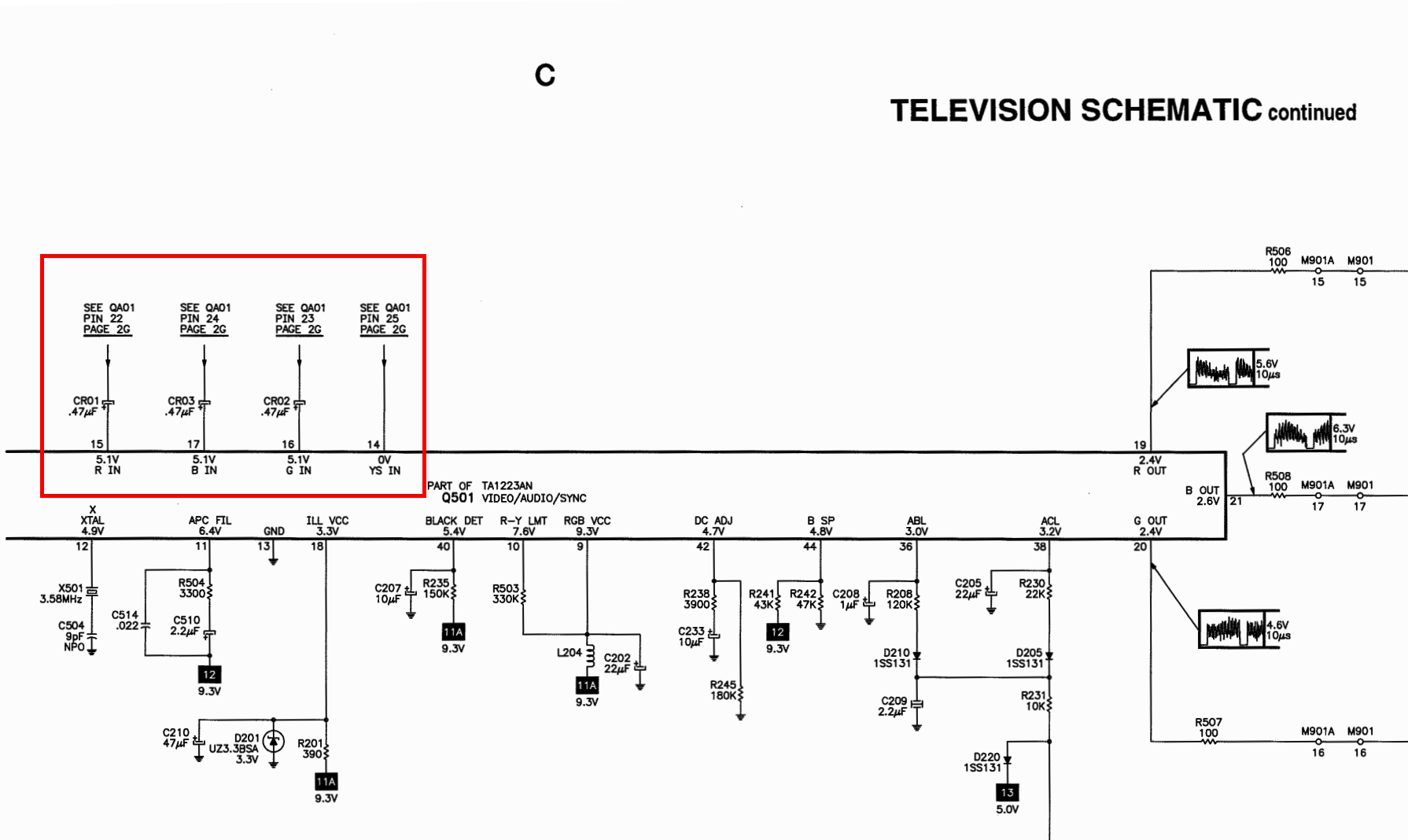 Jungle Chip ^
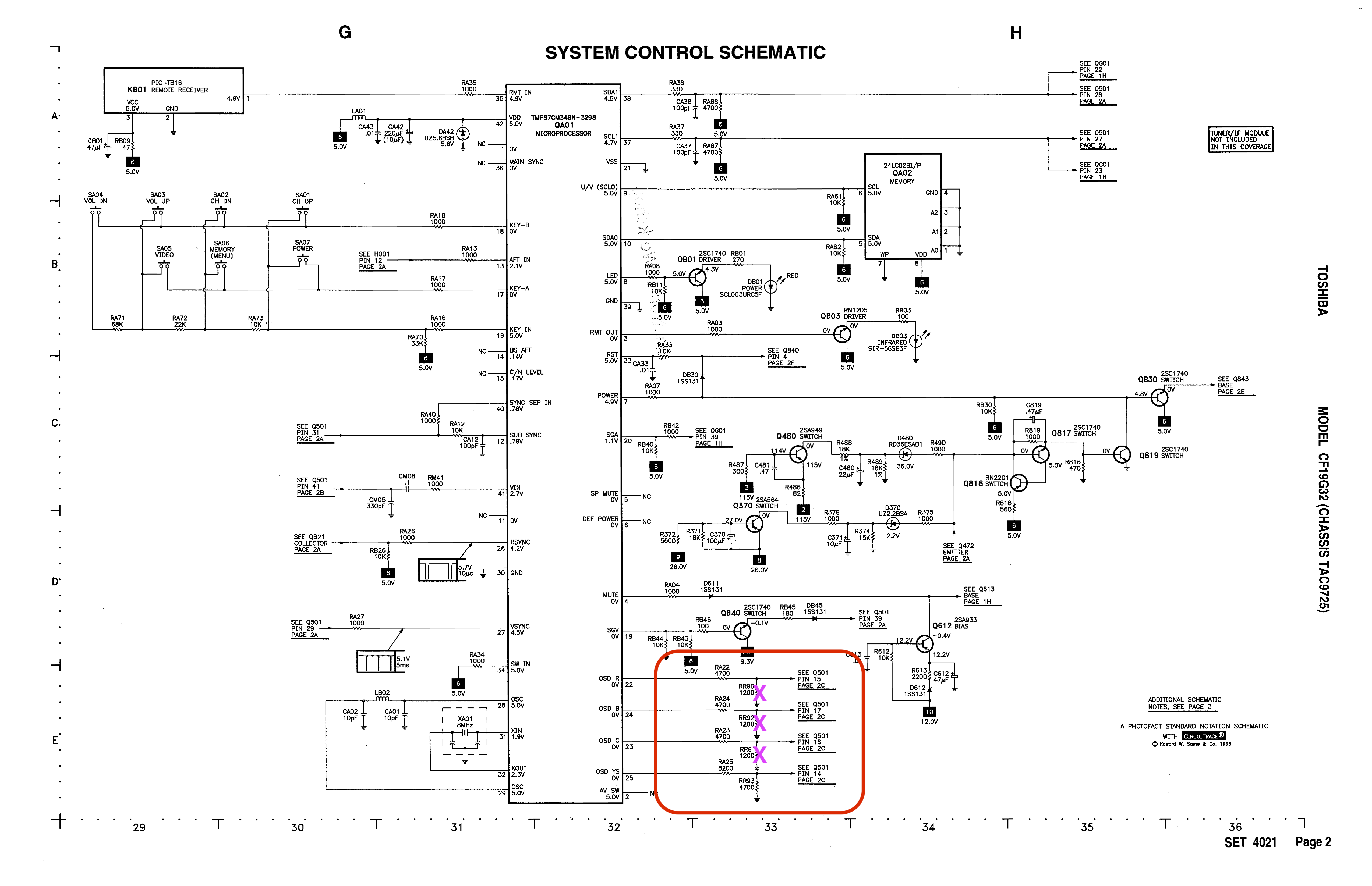 OSD Chip ^
RGB mux diagram
Prepare the mux diagram. If you are building your own circuit, this diagram should help.
Performing the mod
STEP 1: Remove the following components
Remove the three 1.2 kΩ, RGB resistors to ground
- RR90
- RR91
- RR92
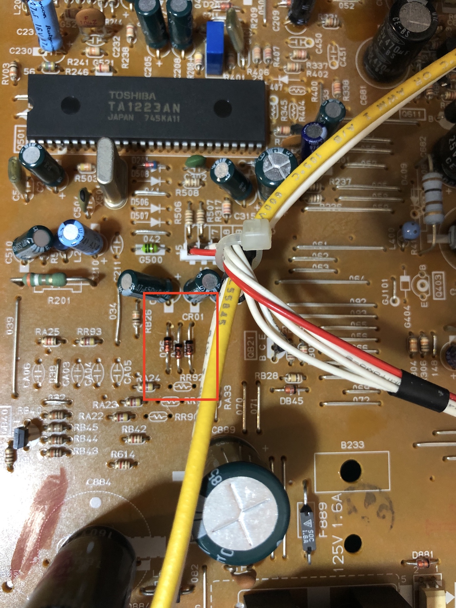
STEP 2: Remove jumpers and install diodes
Remove jumpers 035, 036 and 037. Install diodes (1N4148) in those locations instead. Pay attention to the direction of the diodes. This will prevent the current from going into the OSD, creating a reflection in signal, that causes interference.
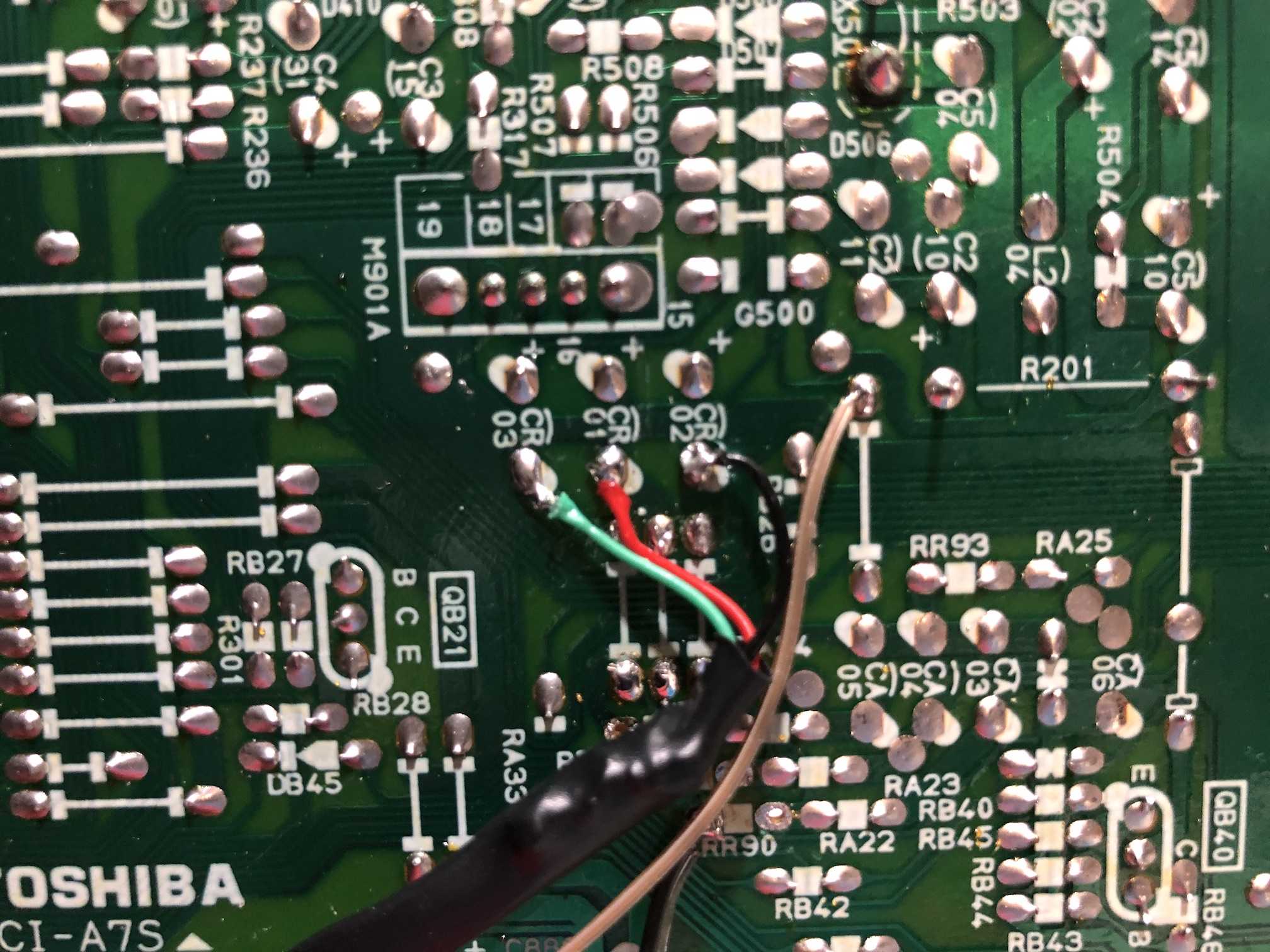
STEP 3: Connect RGBs
Points where the R, G, B and Blank (brown) wires should be connected. Ignore the colors of the wires. I used a shielded wire for this mod. R, G, B wires were not individually shielded. However, there were absolutely no intereference noticed.
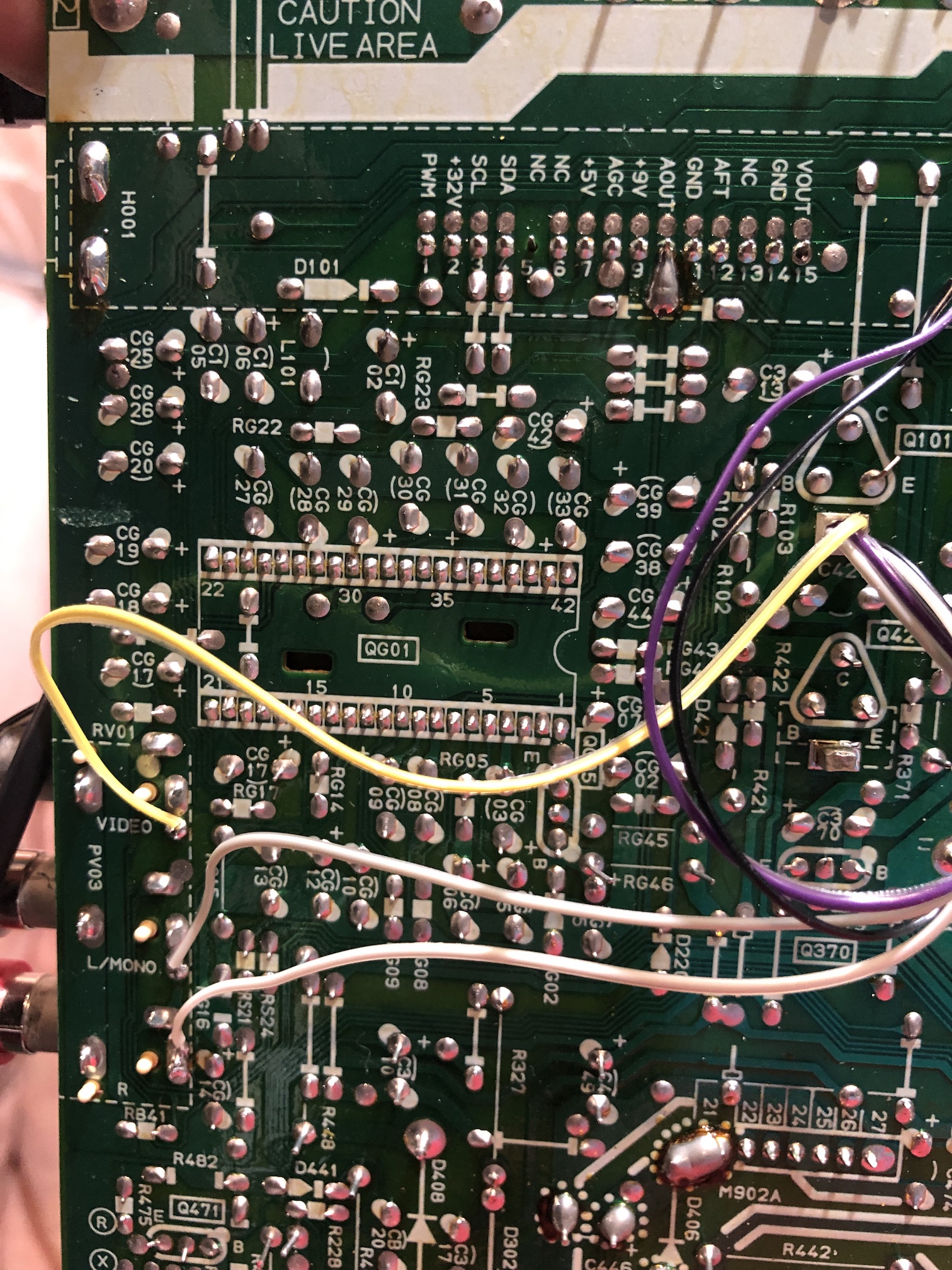
STEP 4: Hook up blanking and Audio
Routed the wires from the top of the board to the bottom side. Some holes were covered with solder. Removed it to expose the holes and routed the wires through them.
Purple and black wires were routed to ground. Yellow wire to composite input pin. White wire to audio left. Gray wire to audio right.
STEP 5: Build your mux circuit
This mod uses the RGB mux board. This is optional, but will make your mod easier and stable. You can also create the circuit presented in the schematics above without the board. Please also checkout the mux calculator to play with your own values.
| On Toshiba CRT Chassis | CF19G32 |
|---|---|
| CRT RGB inline resistor | 4.7kΩ |
| CRT RGB ground resistors removed | 1.2kΩ |
| 0.1μF caps replaced | Yes |
| Add diodes on chassis RGB lines? | Yes |
| Add blanking diode on chassis | Yes |
| Replace blanking resistor on chassis | No |
| RGB mux board | CF19G32 |
|---|---|
| Mux board RGB termination (R1, R2, R3) | 180Ω |
| Mux board RGB inline resistors (R4, R5, R6) | 1kΩ |
| Mux board Audio LR (R7, R8) | 1kΩ |
| Mux board blanking diode (R9) | 1N4148 |
| Mux board blanking ground resistor (R10) | open |
| Mux board blanking resistor (R11) | 4.7kΩ |
Compatible mux boards:
I had to use a RGB tuner gadget I made to find the right balance for RGB termination. It was found using a 150Ω to 180Ω resistor gave the best vibrancy of colors.
STEP 6: Attach the female SCART connector to TV
Creating a SCART cutout and mounting it is an art. I have a dedicated section for it.
SCART connector mounted 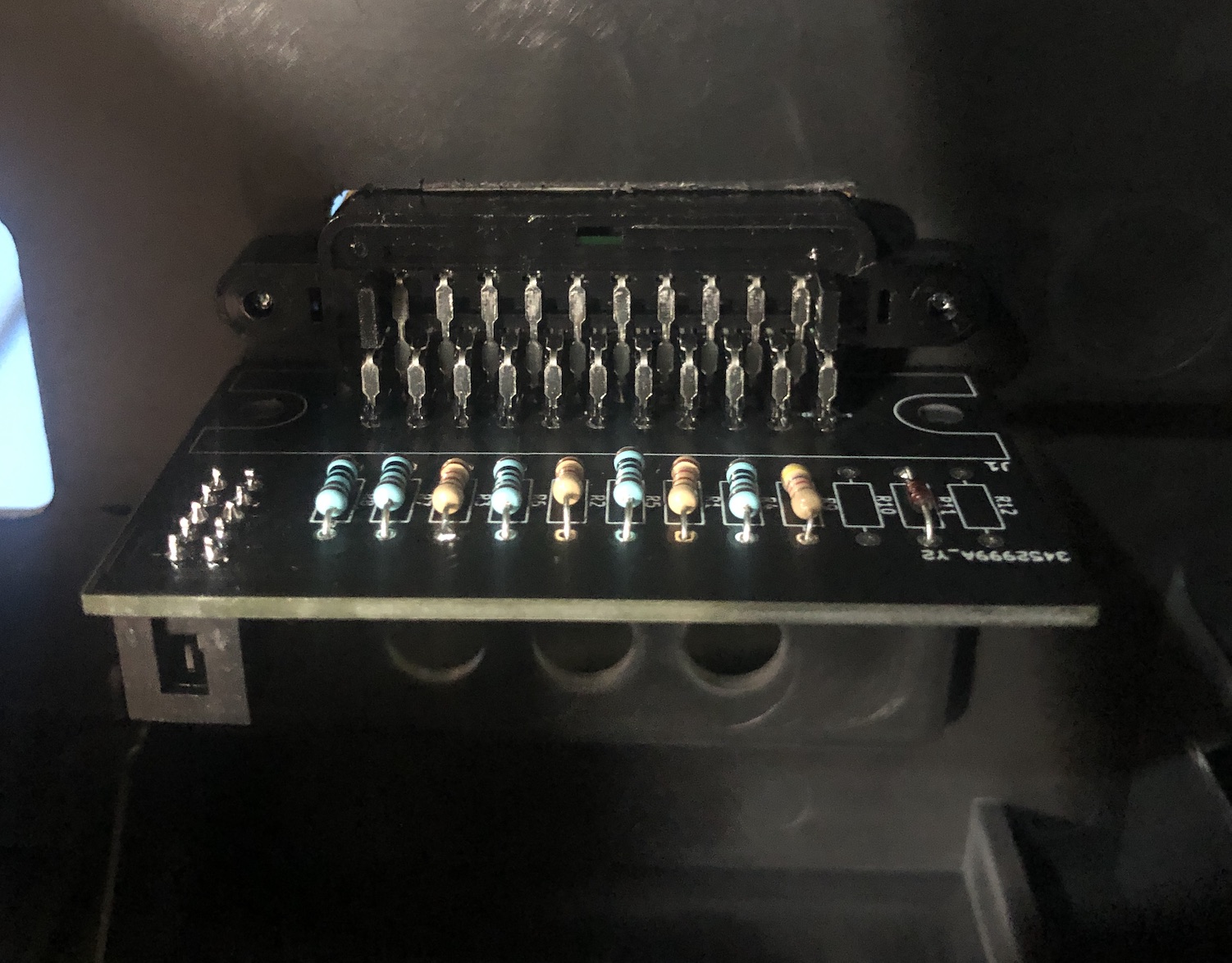
SCART connector 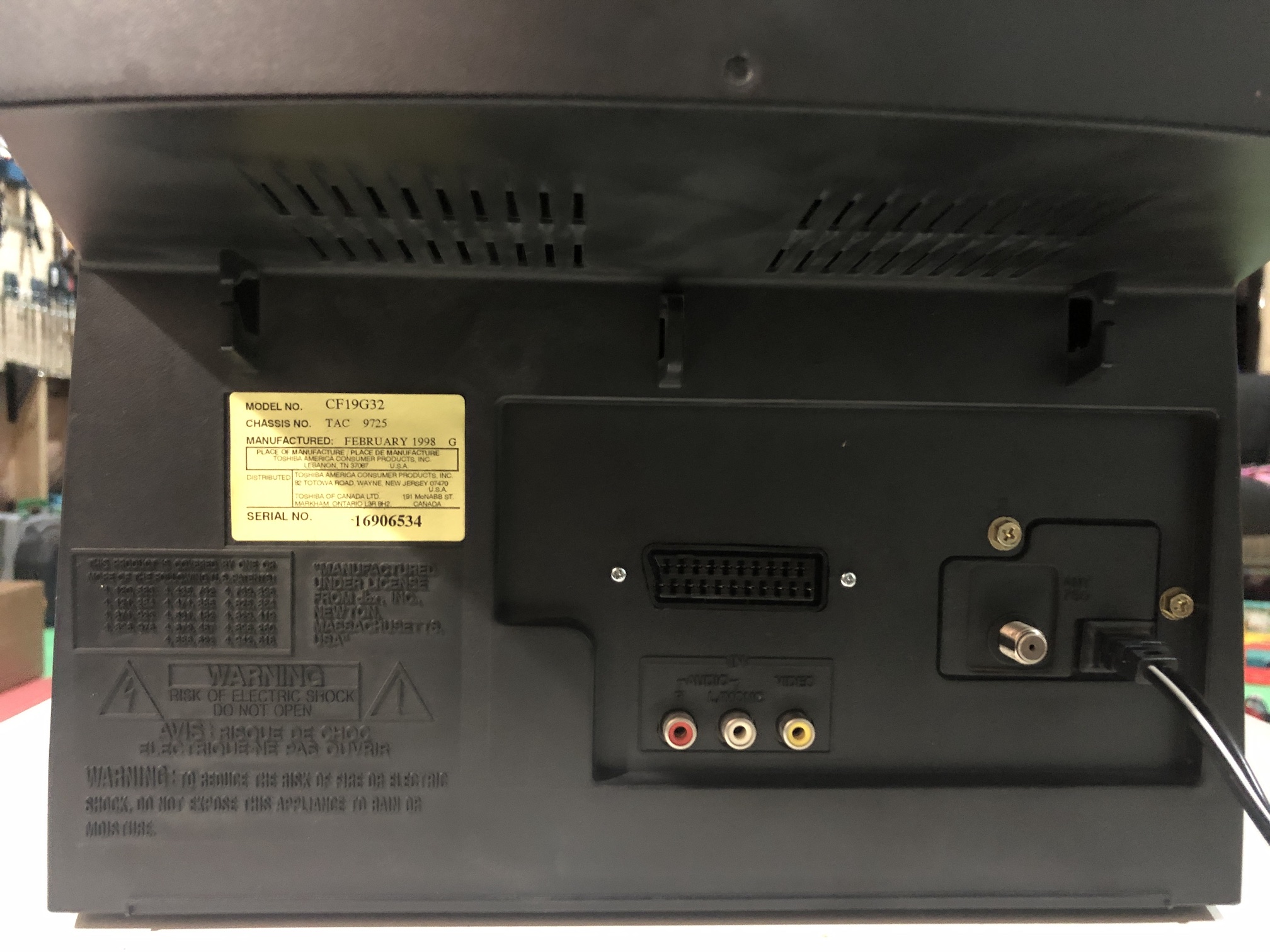
How to create and mount a SCART female plug?
Games
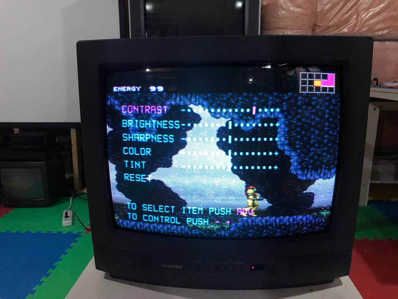
SNES Metroid - OSD Overlay 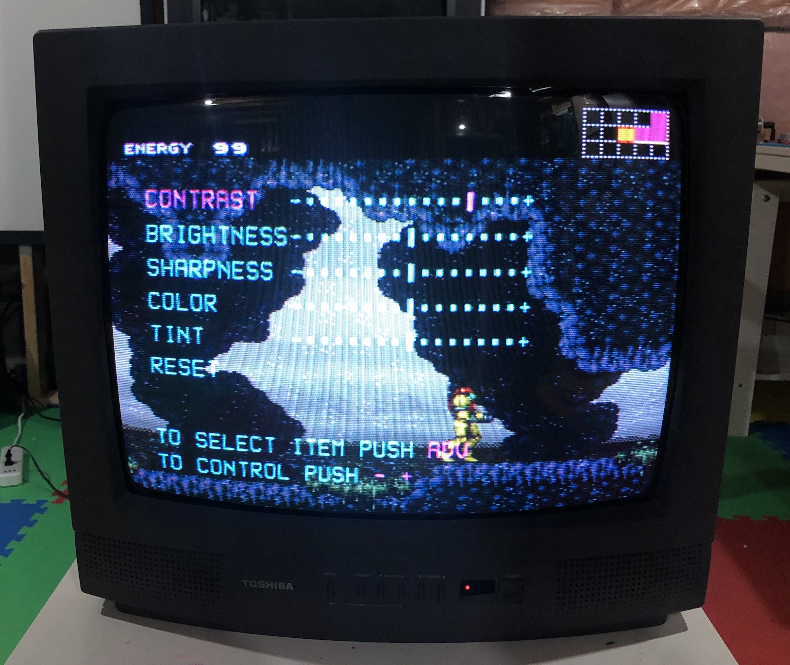
SEGA Genesis - Sonic 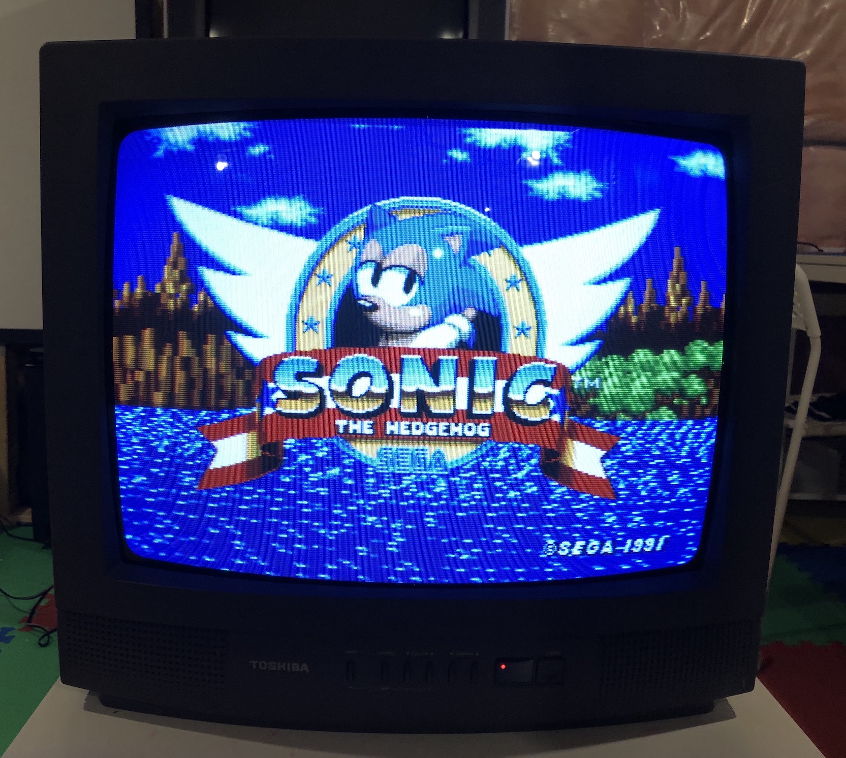
XBOX - UnleashX 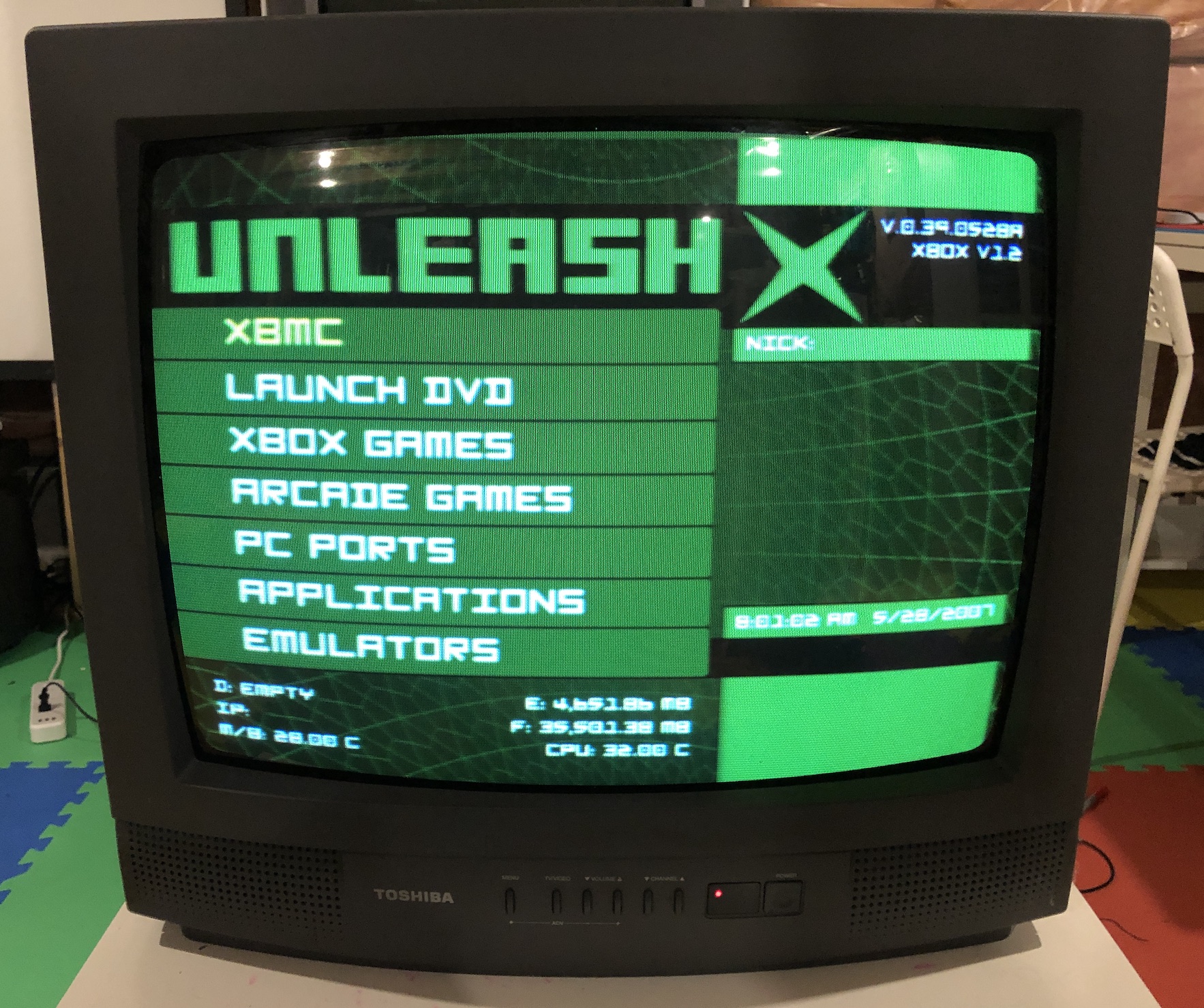
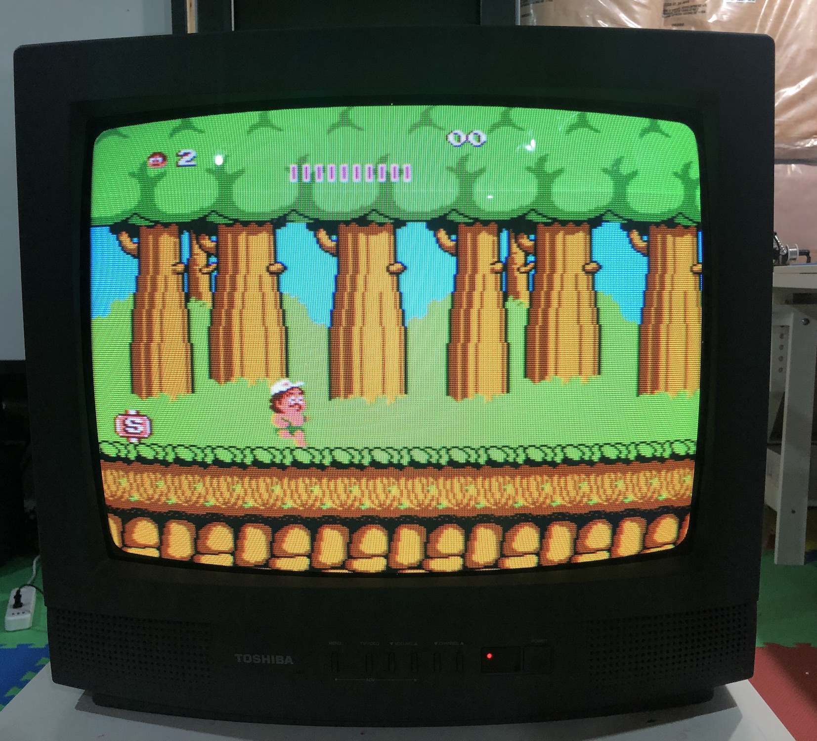
SNES - Super Mario World 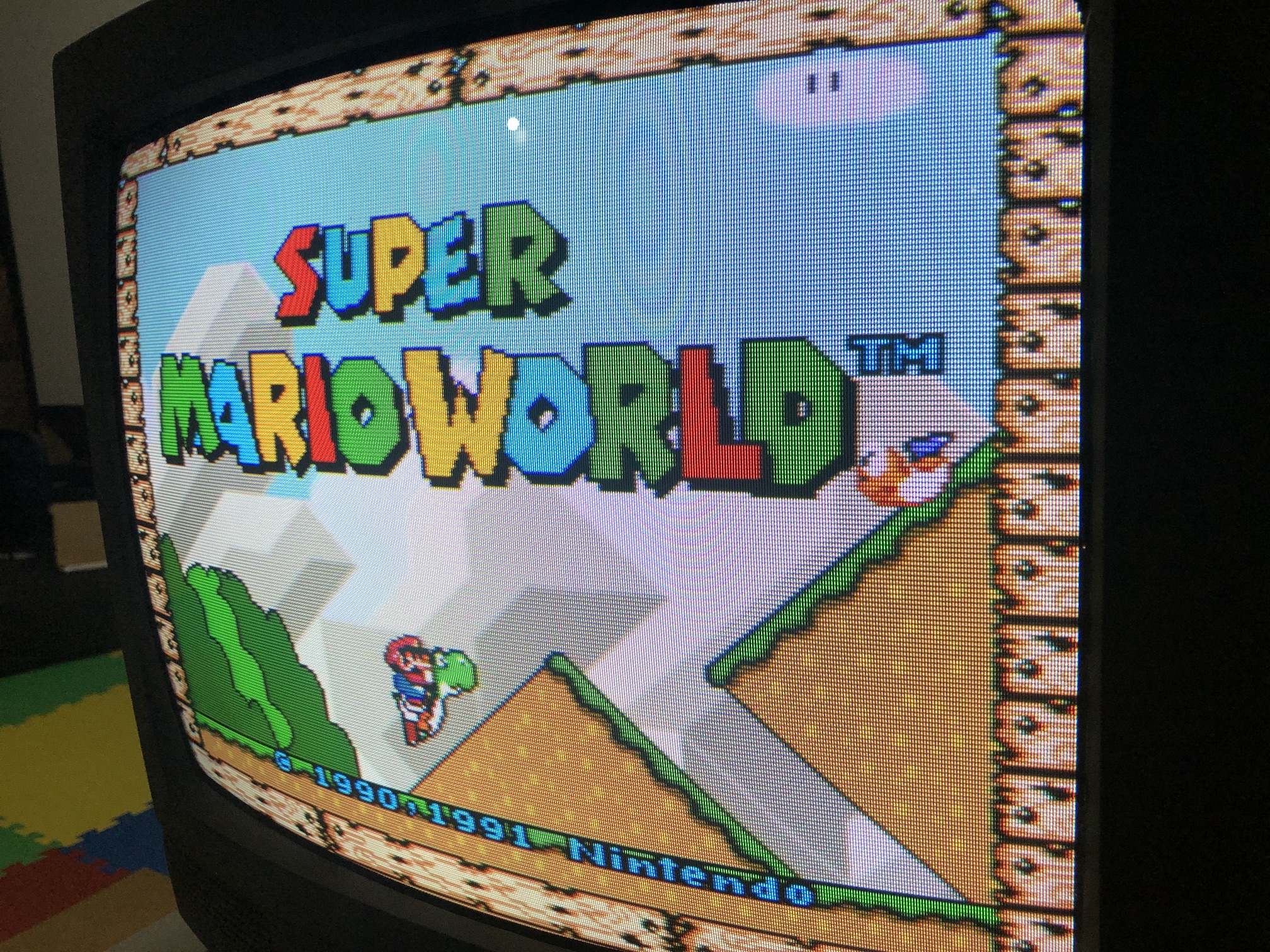
SNES - Super Mario World 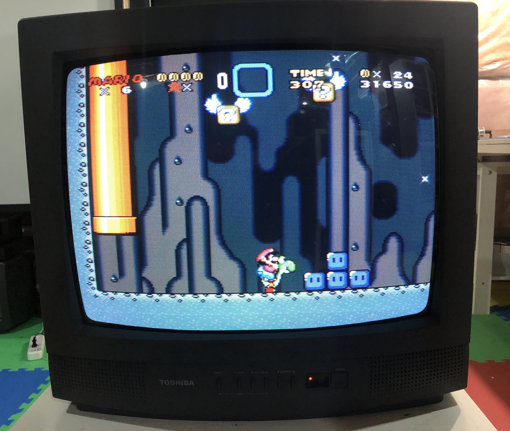
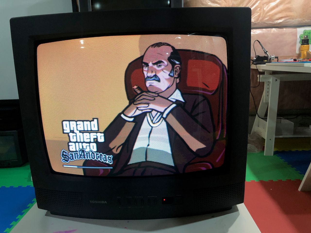
PS2 - GTA San Andreas 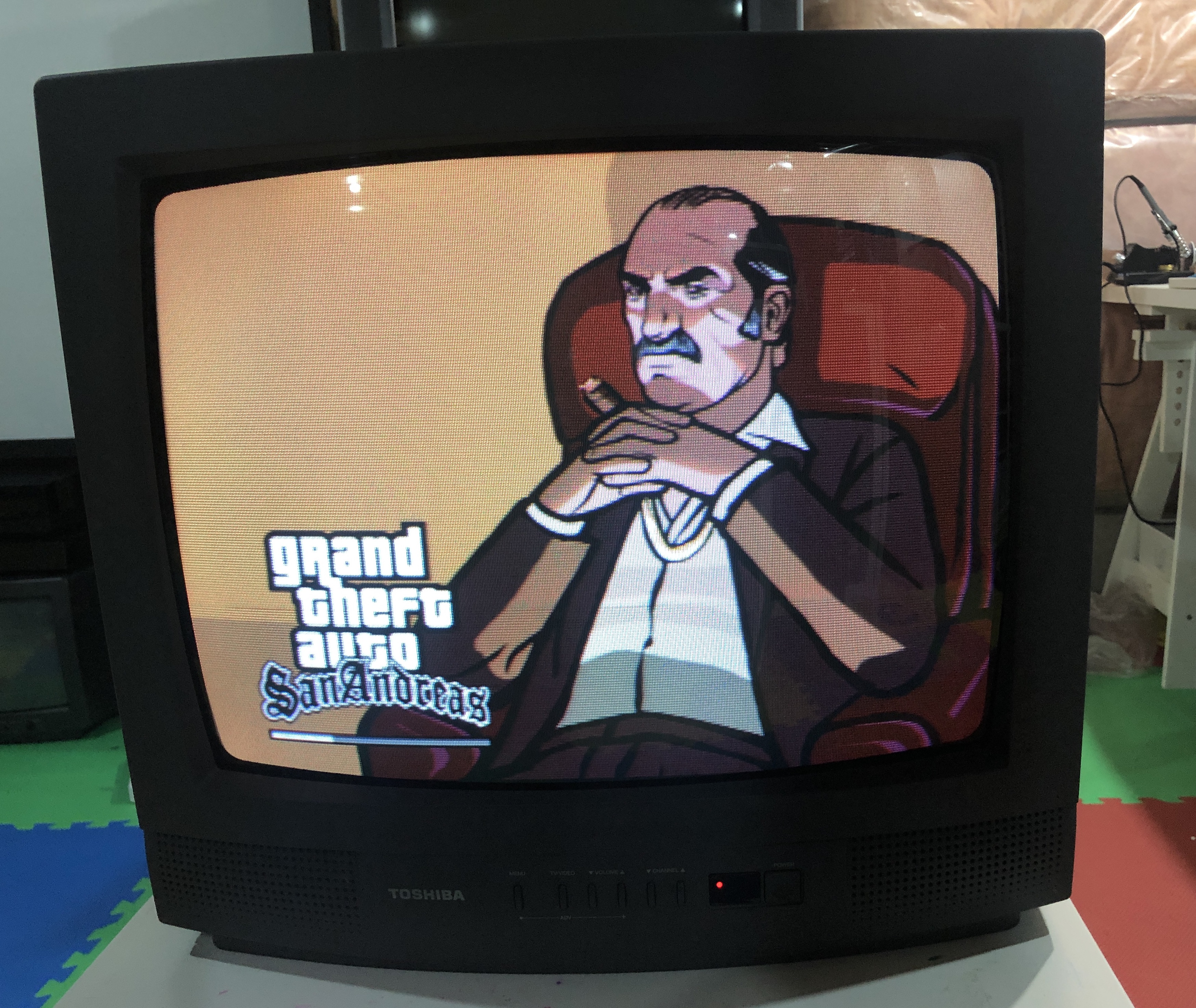
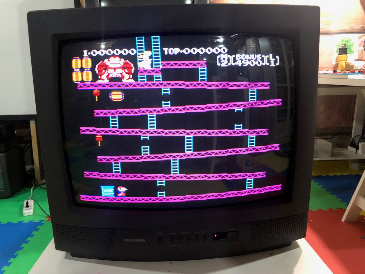
NES - Donkey Kong 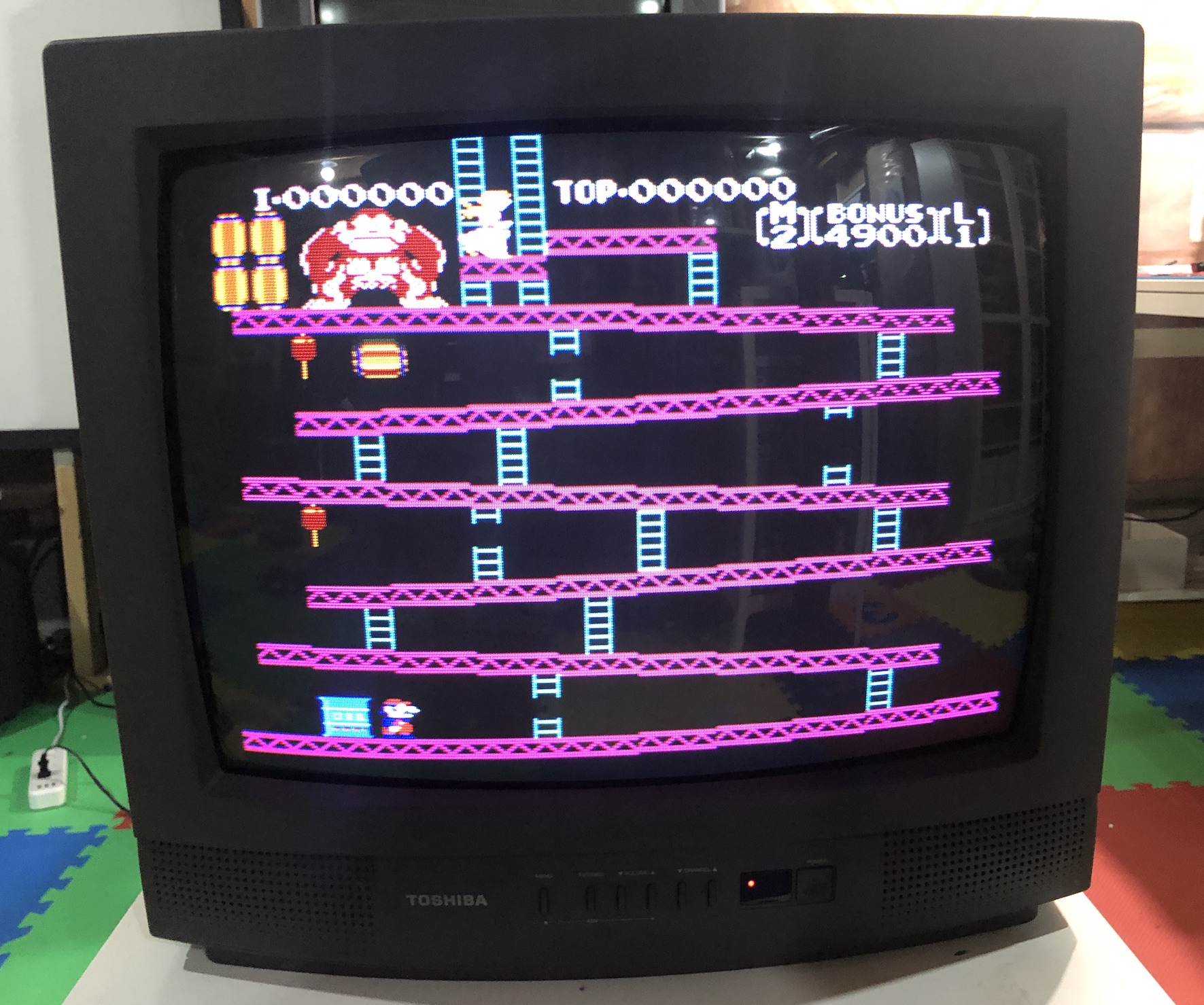
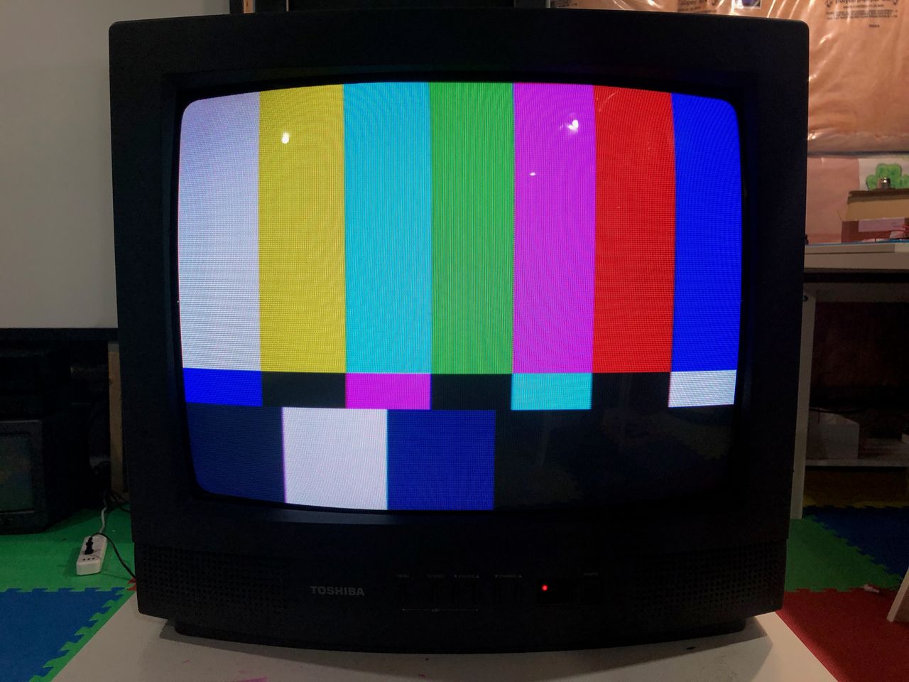
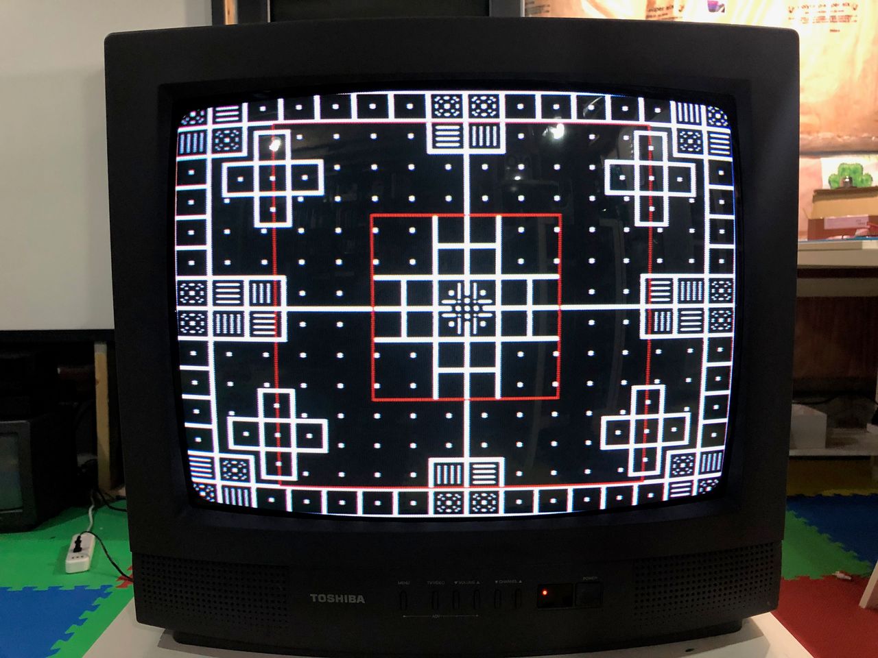
Patterns
240p - Grid 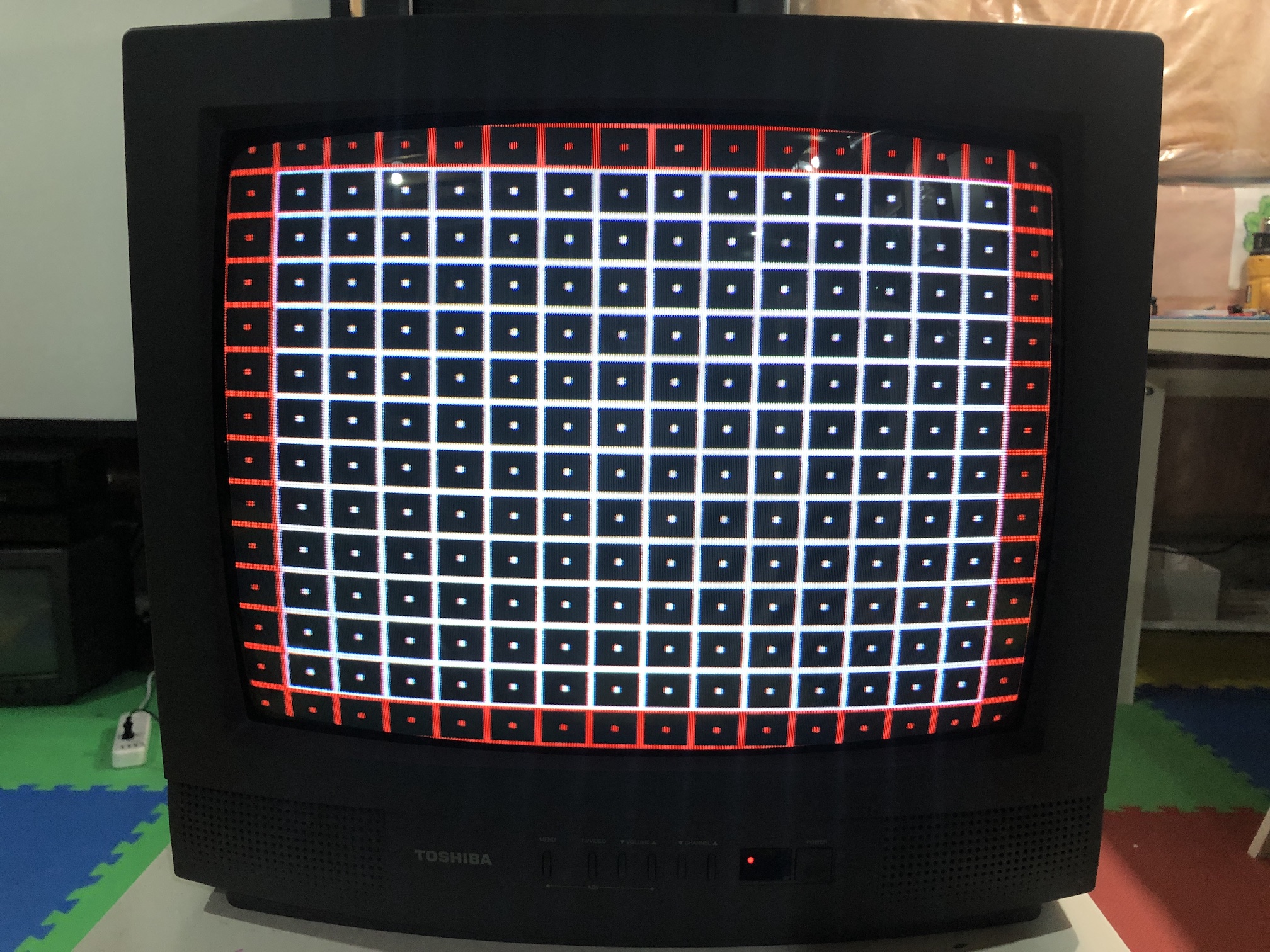
Other pictures
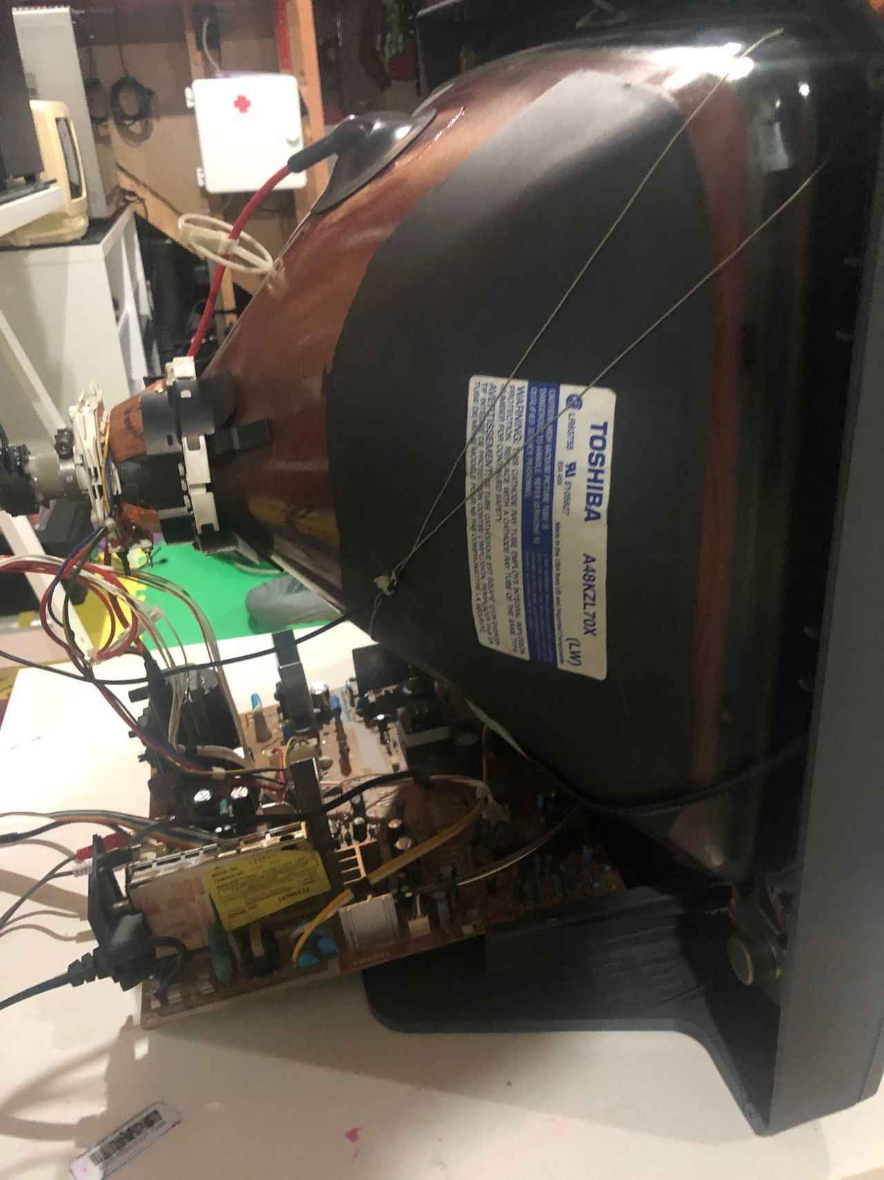
Main Chassis 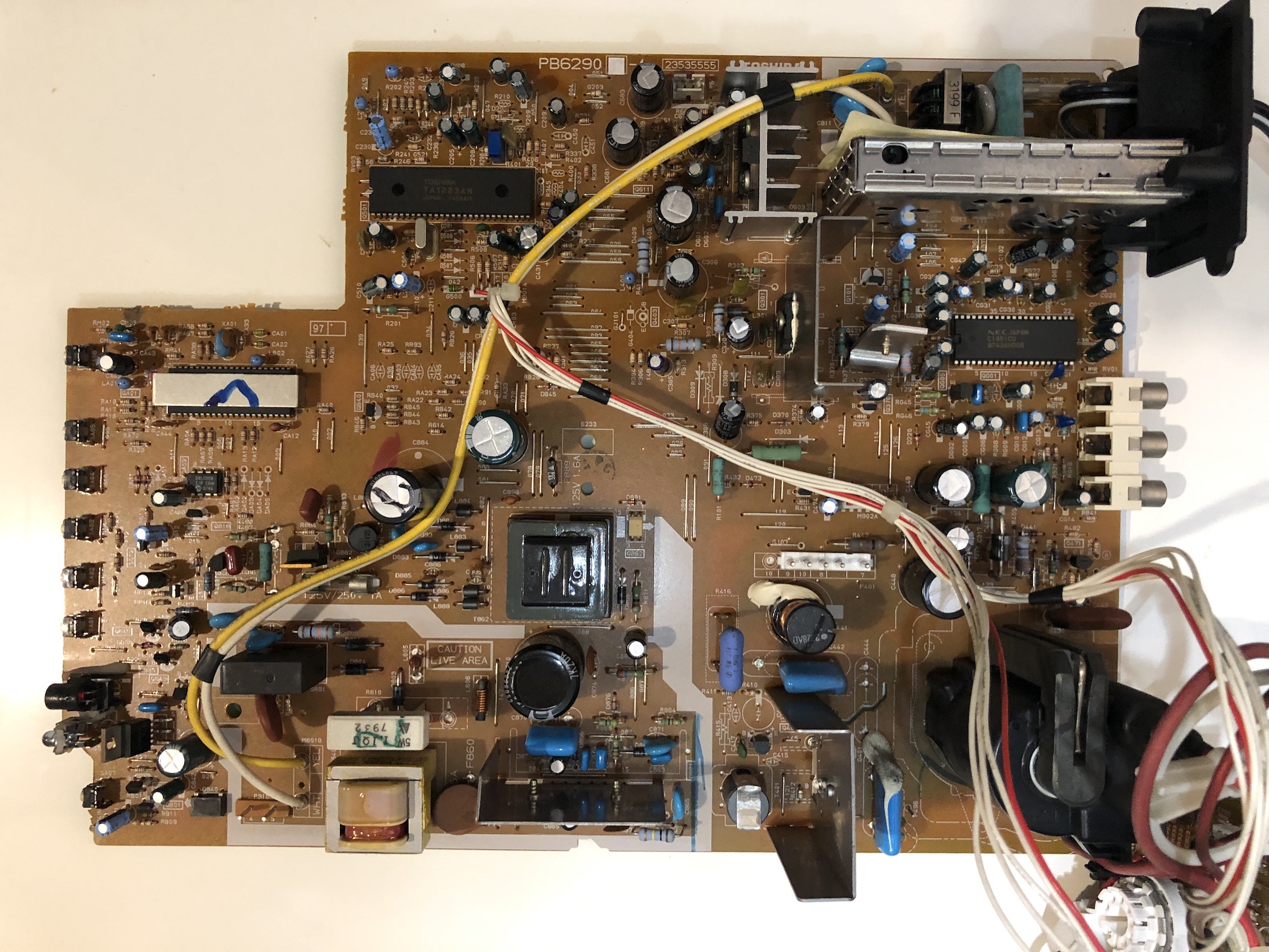
Neck Board 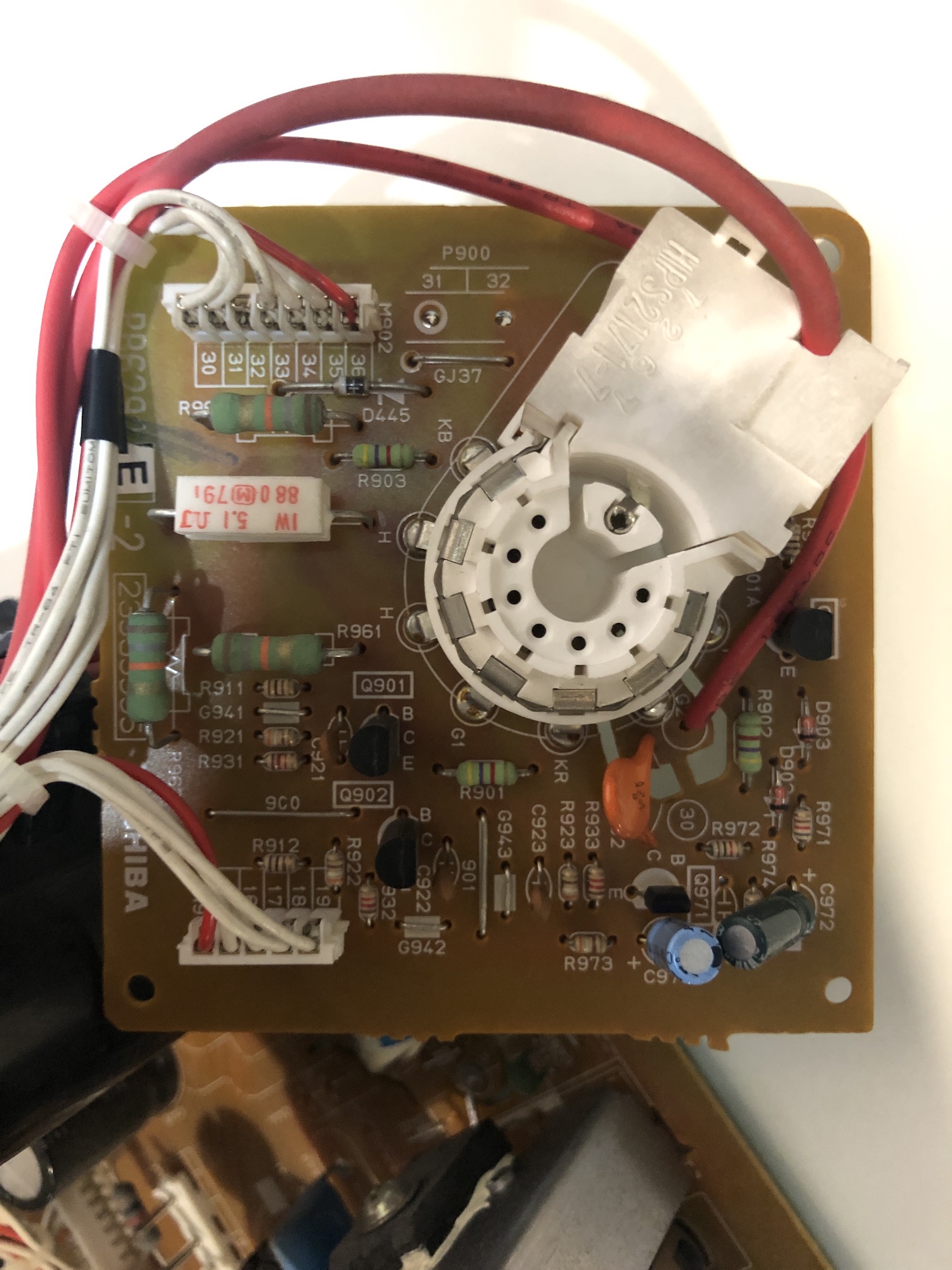
Tube 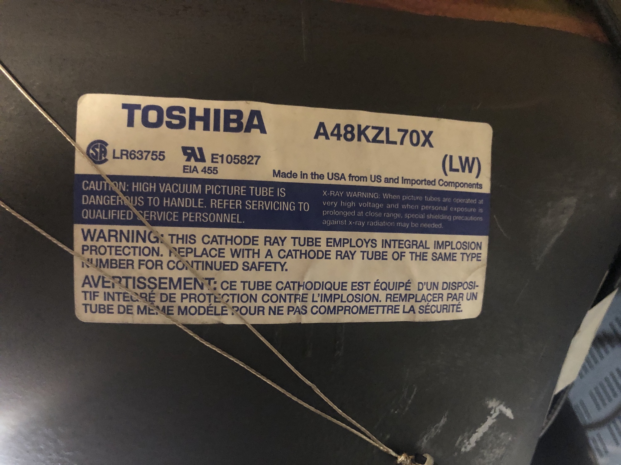
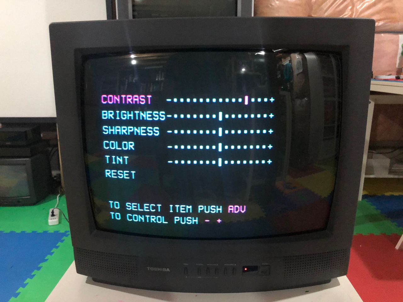
Service Menu
Press Mute on the remote and press Menu on the CRT to enter Service Mode
Press Menu again on the CRT for options. CH buttons to change option. VOL buttons to increase/decrease values
- AUD - 00H
- HPOS - 19H
- VPOS - 05H
- HIT - 1DH
- RCUT - 7CH (default)
- GCUT - 42H (default)
- BCUT - 6AH (default)
- GRDV - 6DH (default)
- BDRV - 82H (default)
- BRTC - 38H
Design mode
Press Recall on the remote and press Menu on the CRT to enter Design Mode
Pictures
Reference Photos