Samsung GXE-1395
Samsung GXE-1395 CRT RGB mod
RGB Mod for Samsung KG-1 CRT televisions. Written by Brendan Eddy (FlyingFlygon).
Credits to: MarkOZLAD and Syntax for method

View full CRT details and more mod examples →
Contributors
Thank you to everyone who contributed to this guide:
- Brendan Eddy — photos and documentation
- Andy King — contributor, CRT specs from CRT Database.
CRT safety
Caution
You can die doing this! So read carefully! CRT TV is not a toy. Do not open a CRT TV. If you don't have any prior knowledge about handling high voltage devices, this guide is not for you. CRT TV contains high enough voltage (20,000+ V) and current to be deadly, even when it is turned off.
Plan of attack
Service manuals
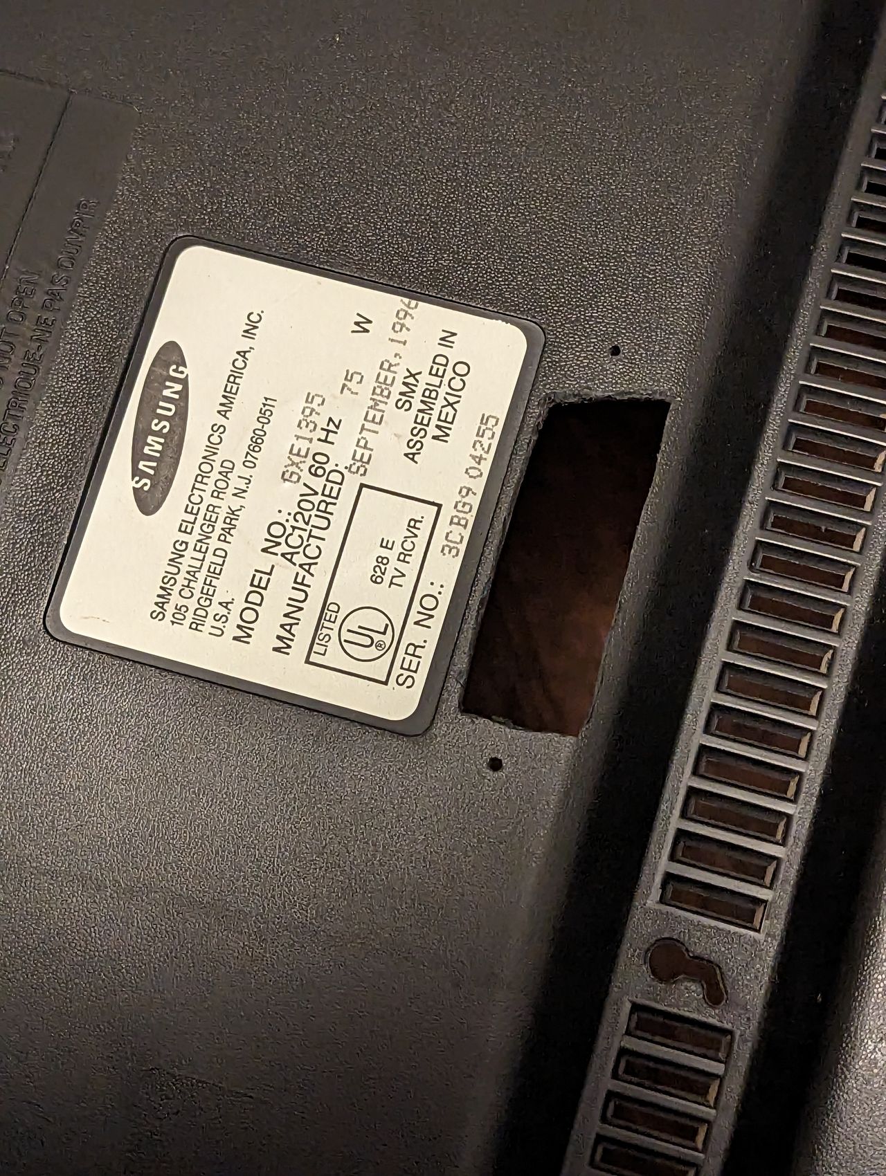
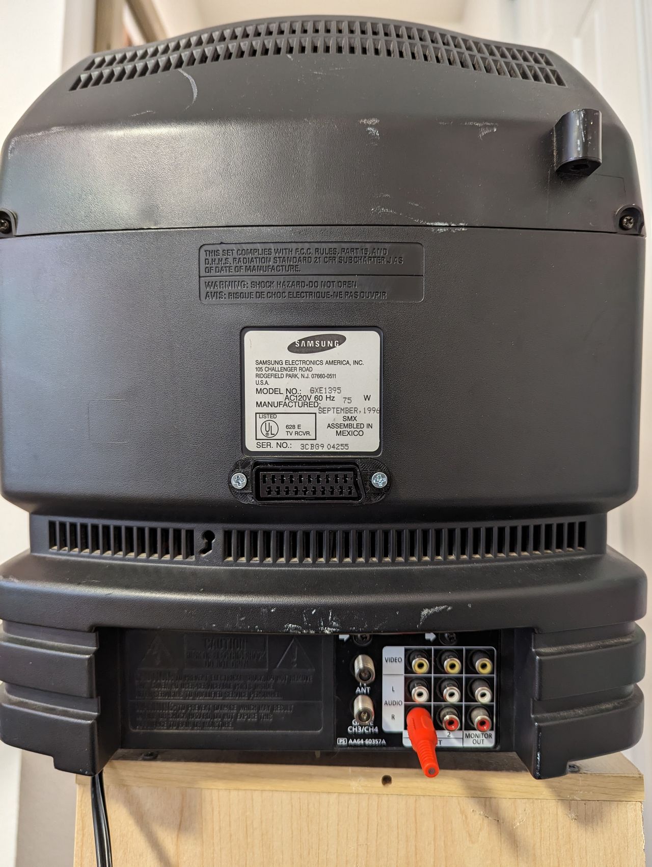
Specs
- Year: 1996
- Format: NTSC
- Chassis: KG1
- Tube: Samsung A34KQV42X
- Jungle Chip: Toshiba TA1201AN
- OSD Chip: UPC1853
- Screen Size: 13"
- Inputs: Composite, RF
RGB mux diagram
This mod uses the RGB mux board. This is optional, but will make your mod easier and stable. You can also create the circuit presented in the schematics above without the board. Please also checkout the mux calculator to play with your own values.
| Component | Value |
|---|---|
| RGB/OSD inline resistor (chassis) | 3.9kΩ |
| Removed RGB/OSD resistor (chassis) | 630Ω |
| RGB inline diode method (chassis) | Yes |
| RGB termination (R1, R2, R3) | 75Ω |
| RGB inline (R4, R5, R6) | 680Ω |
| Audio LR (R7, R8) | 1kΩ |
| Diode (R9) | 1N4148 |
| Blanking Ground Resistor (R10) | open |
| Blanking Resistor (R11) | 0μF |
Pictures
Photos by Brendan
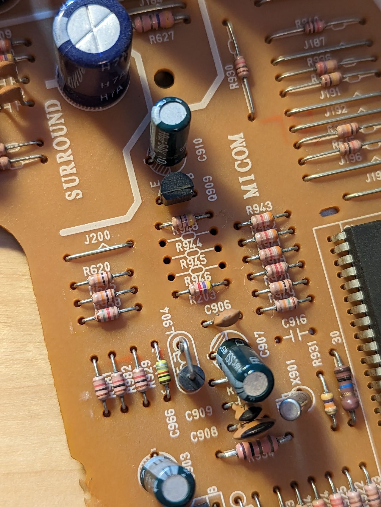
Remove the grounding resistors on the RGB lines:
- R944 (560Ω)
- R945 (560Ω)
- R946 (560Ω)
Place jumper wire on resistor R948 to jump it to ground, disabling the closed caption display circuit. This circuit is known to dim the image. See MarkOZLAD's Samsung RGB mod guide for more info.
Remove jumper wire J104 which is located right off the composite input AV1. If you do not do this step, the mod can still work, but you will have an OSD message overlay which states "Connect the AV1 jacks". Once this jumper is removed, that check is disabled and the message goes away.
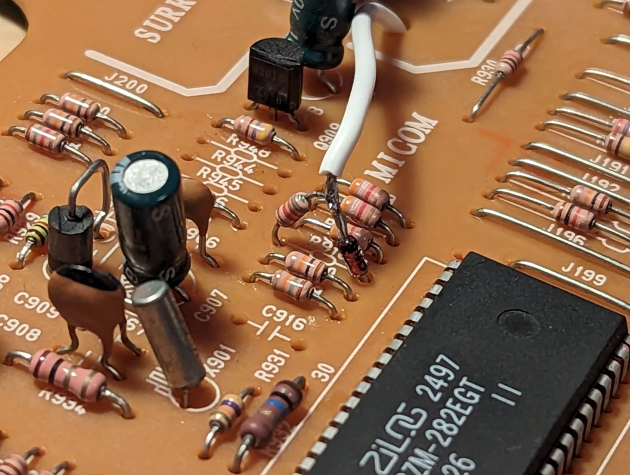
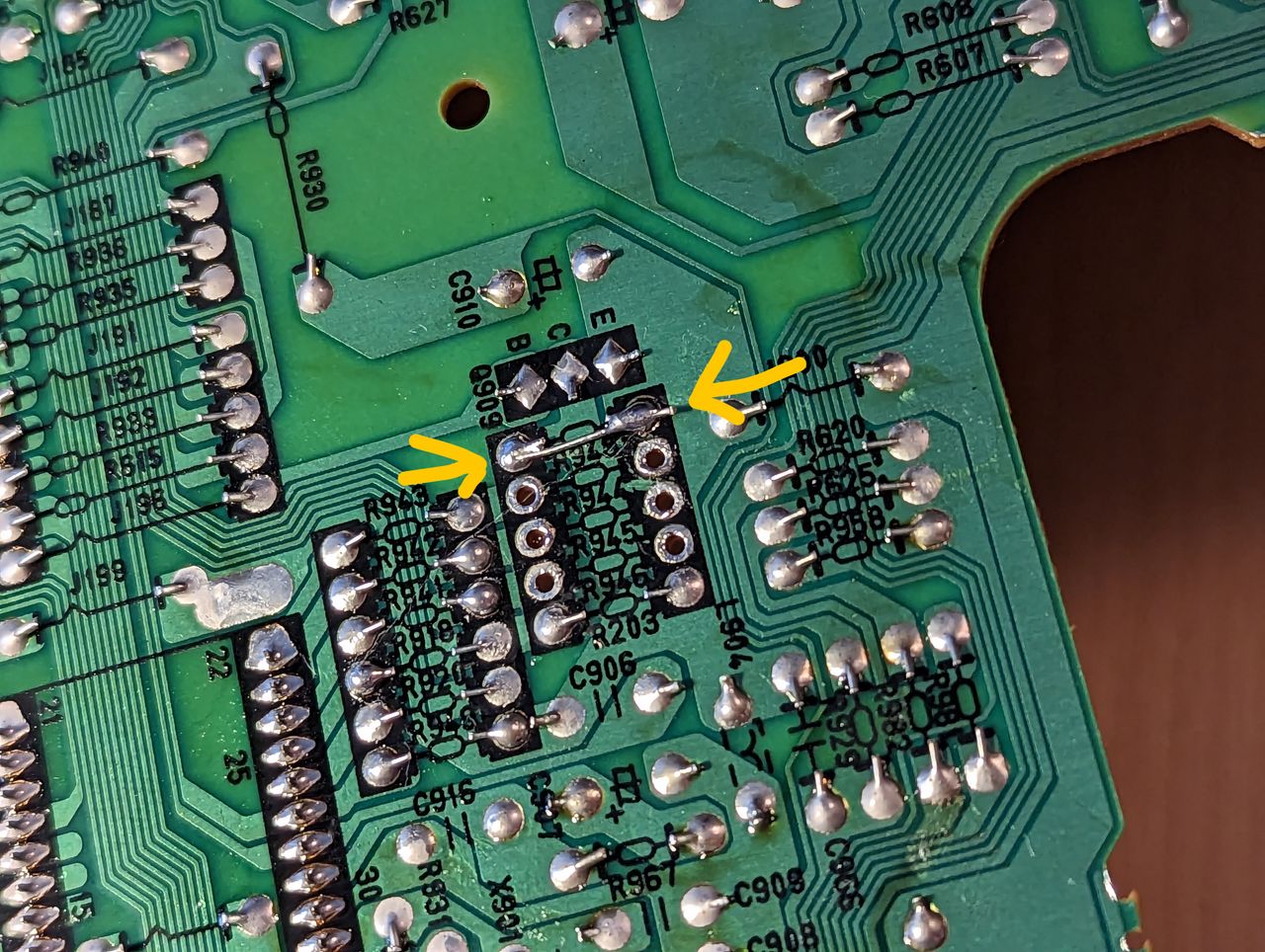
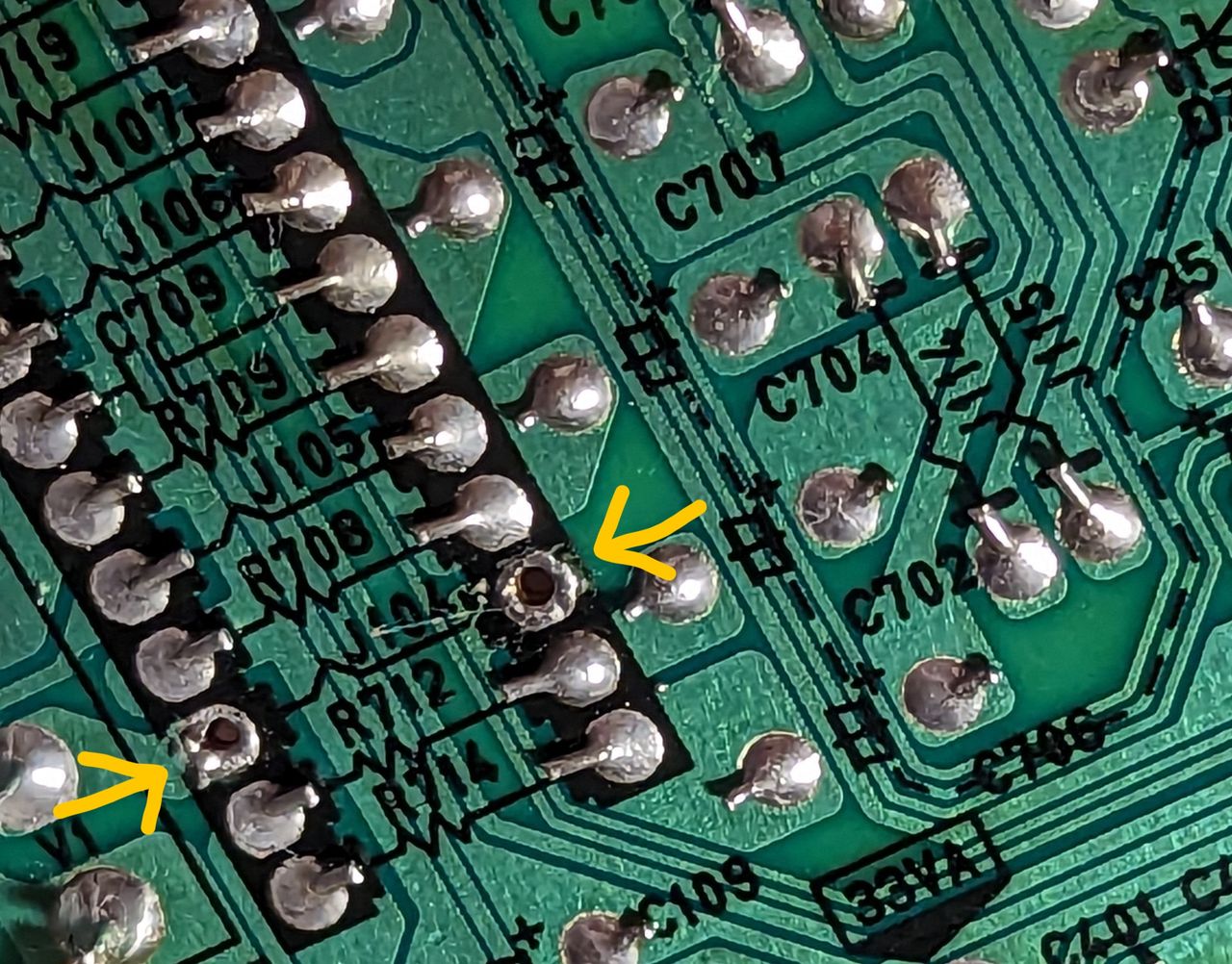
Desolder the leg of resistor R918 that's on the side near the Micom chip. Insert the cathode end of a 1N4148 diode in its place. Solder the remaining legs of the diode and R918 together.
Connect your RGB and blanking wires to the board.
- 5V Blanking goes in between the diode and R918 (see pic above)
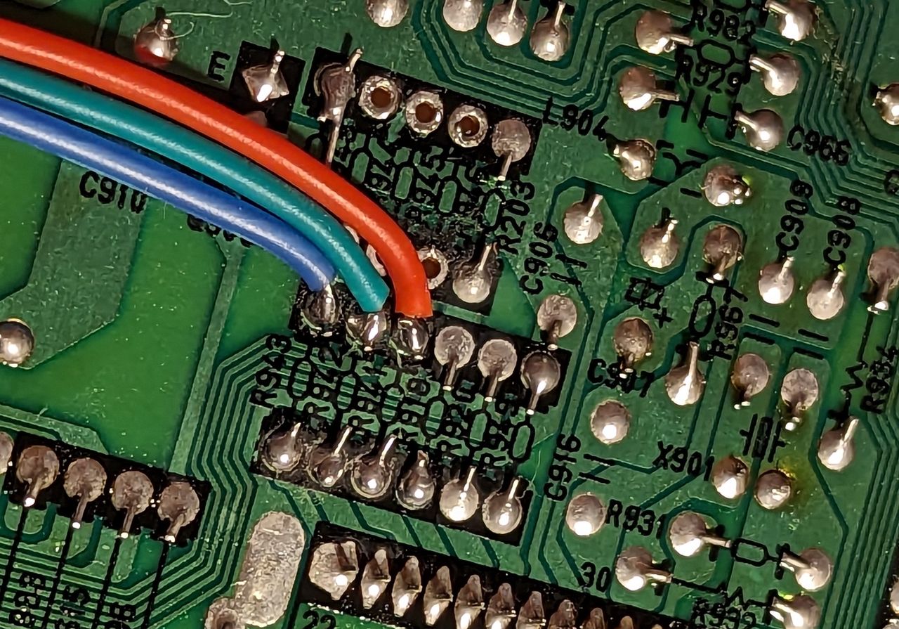
- Red, green, and blue go to the EXITING end of resistors R941, R942, R943 respectively.
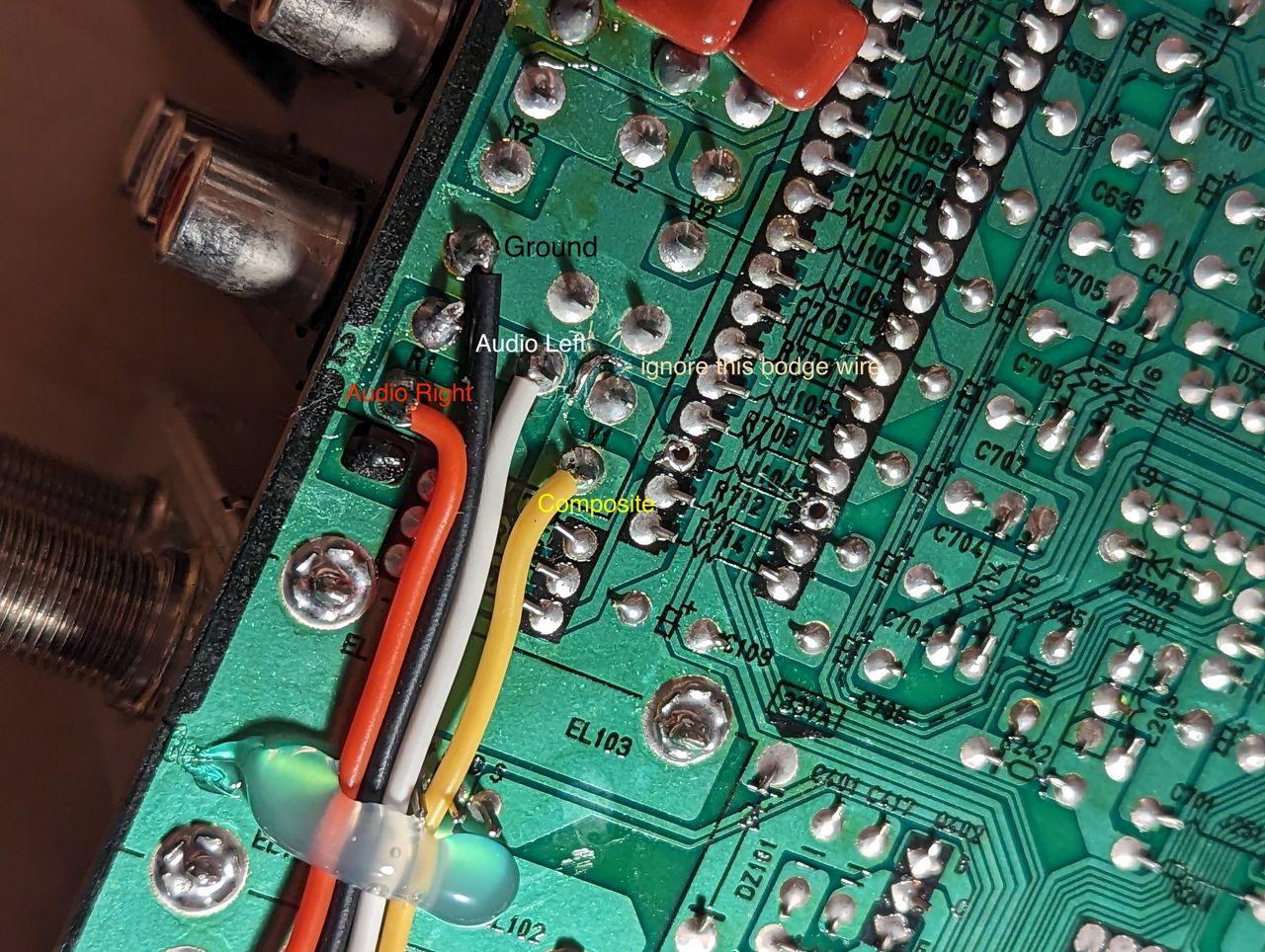
Connect your ground, composite (sync) and (if using SCART) audio wires to the board. All of these can be obtained directly from the pins on AV1.
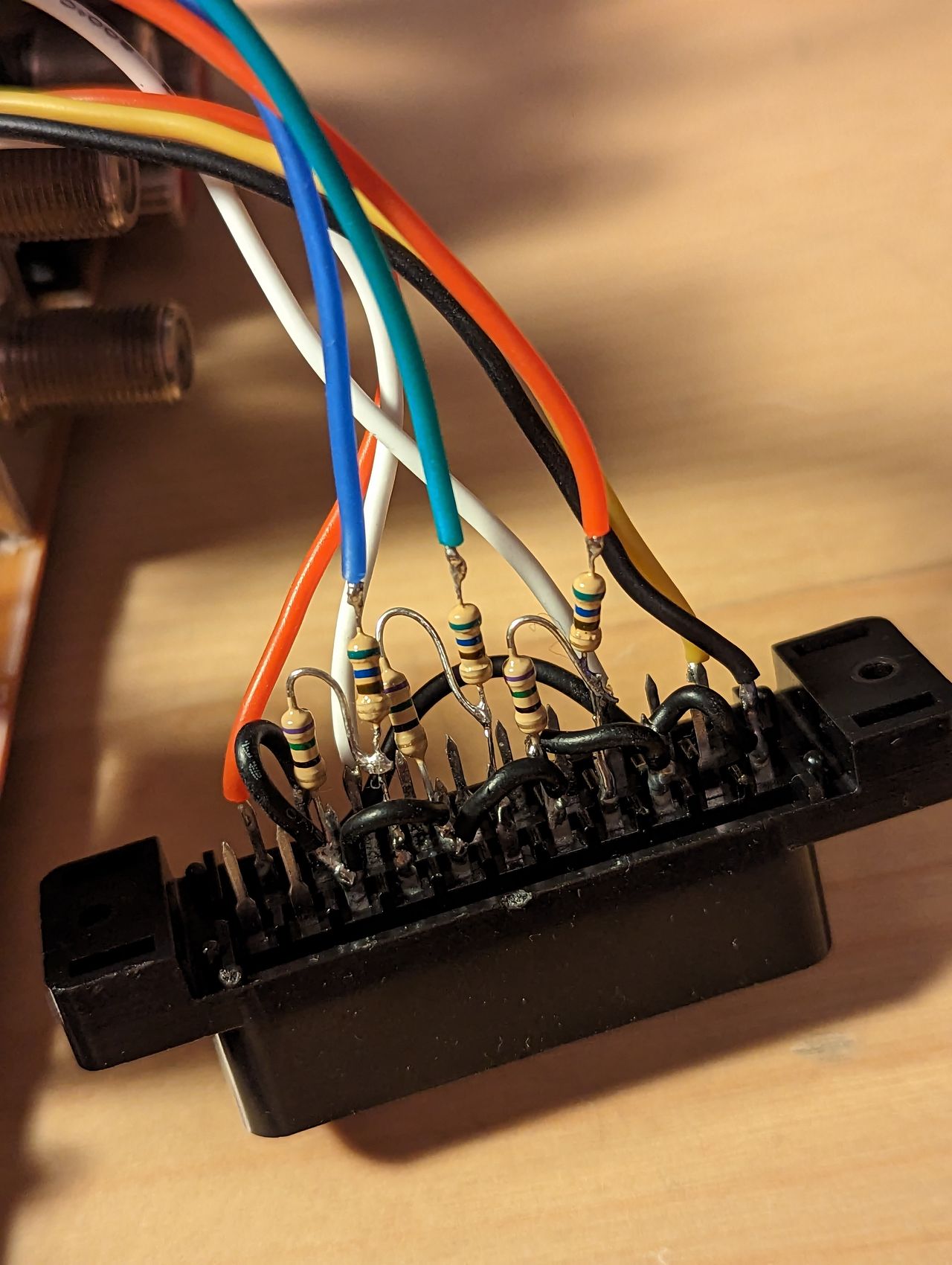
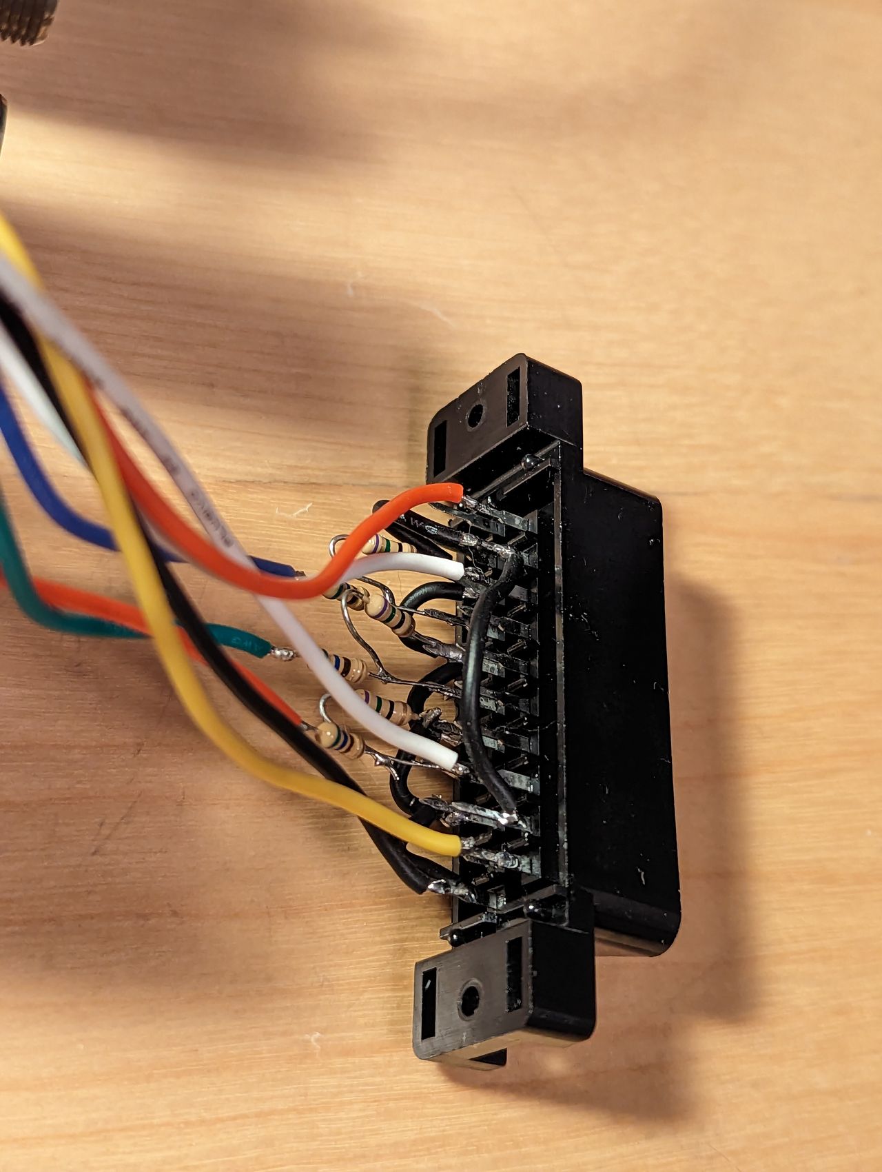
Prepare your SCART/BNC connectors. Inline resistors are 560 Ohms. Terminating resistors are 75 Ohms. Make sure grounds are connected. My implementation uses SCART.
Cut necessary holes in the back housing to fit your connectors.
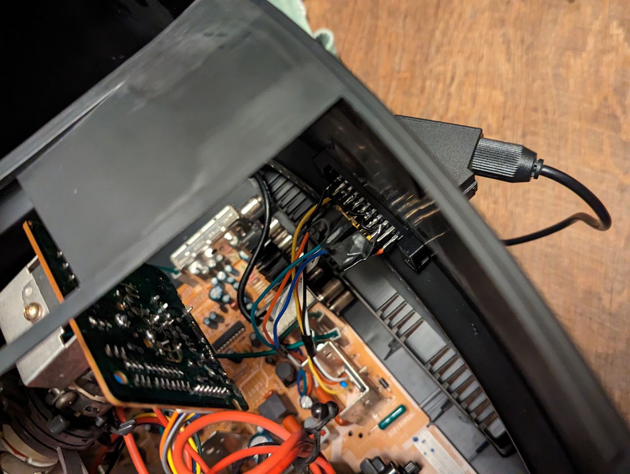
The subwoofer on this TV takes up large channels to the left and right of the neckboard. Also, the space to the left of the AV inputs is either very close to heatsinks, resulting in no room for connectors, or directly next to the flyback transformer, which can interfere with your signals. See here for a demonstration on the effect of the FBT when the SCART port is too close.
With these in mind, I found the best place for my SCART port to be directly under the neckboard. This isn't the prettiest spot, but it ended up having no negative effect on my signals, and did not interfere with the subwoofer's housing.
Read This!
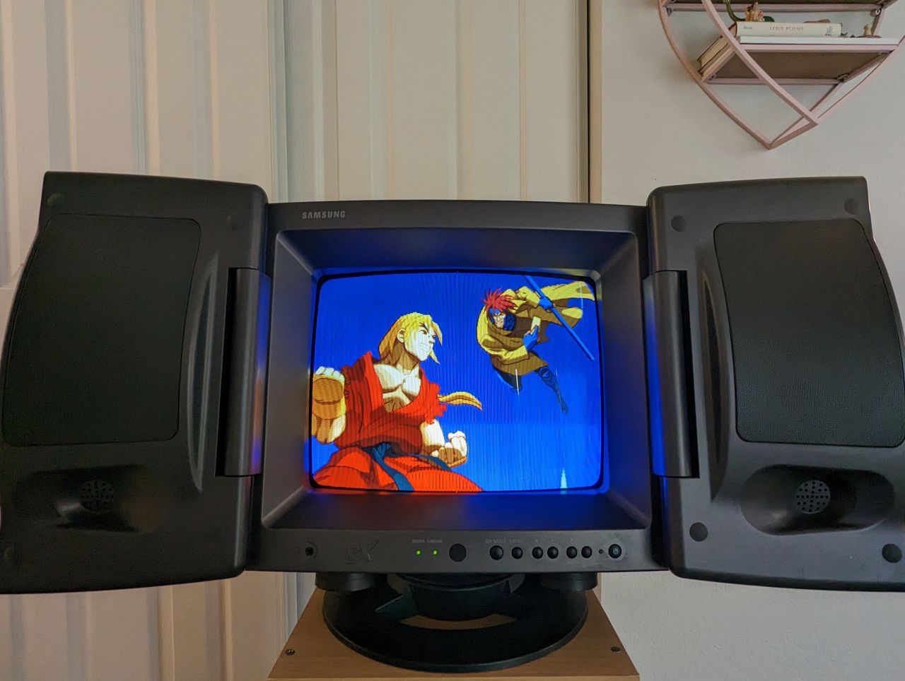
The RGB input will likely look too bright/washed out. Even though our signal is 0.7V, it seems these Samsungs display the analog RGB quite bright. The fix for this is to reduce the screen voltage a tad. Using a small philips screwdriver, reduce the "Screen" potentiometer which is located on the back of the flyback transformer. A small reduction will result in a perfect balance of colors in RGB. Note, this will reduce the brightness of the composite input. You can increase the default menu's Brightness and Picture settings to compensate for this, because the RGB bypasses them anyway.


Reference Photos