Sony (BG-3R) KV-XA34M31
Sony (BG-3R) KV-XA34M31 CRT RGB mod
Below mod was performed on a 34" Sony KV-XA34M31 by Mark Robertson. BG-3S chassis is identical to BG-3R and the below RGB mod method can be applied to it as well.
This mod should also work on the following sets.
- KV-XA29M31
- KV-XJ29M31
- KV-XJ29M50
- KV-XJ29M60
- KV-XJ29M80
- KV-XJ29M81
This set supports composite, s-video and component natively. After the below modification, it also supports RGB via SCART input.
The Sony KV-XA34M31 is a 34" FD Trinitron "pure flat" CRT television released around the year 2000, known for its high quality image, component video input, and robust performance. Manufactured in Malaysia, this model is part of the later era of Sony CRTs.
This CRT is RGB moddable.
View full CRT details and more mod examples →
Contributors
Thank you to everyone who contributed to this guide:
- Mark Robertson — contributor, RGB mod and pictures
CRT safety
Caution
You can die doing this! So read carefully! CRT TV is not a toy. Do not open a CRT TV. If you don't have any prior knowledge about handling high voltage devices, this guide is not for you. CRT TV contains high enough voltage (20,000+ V) and current to be deadly, even when it is turned off.
Plan of attack
Manuals and Datasheets
Specs
- Manufactured: Malaysia
- Chassis: BG-3R
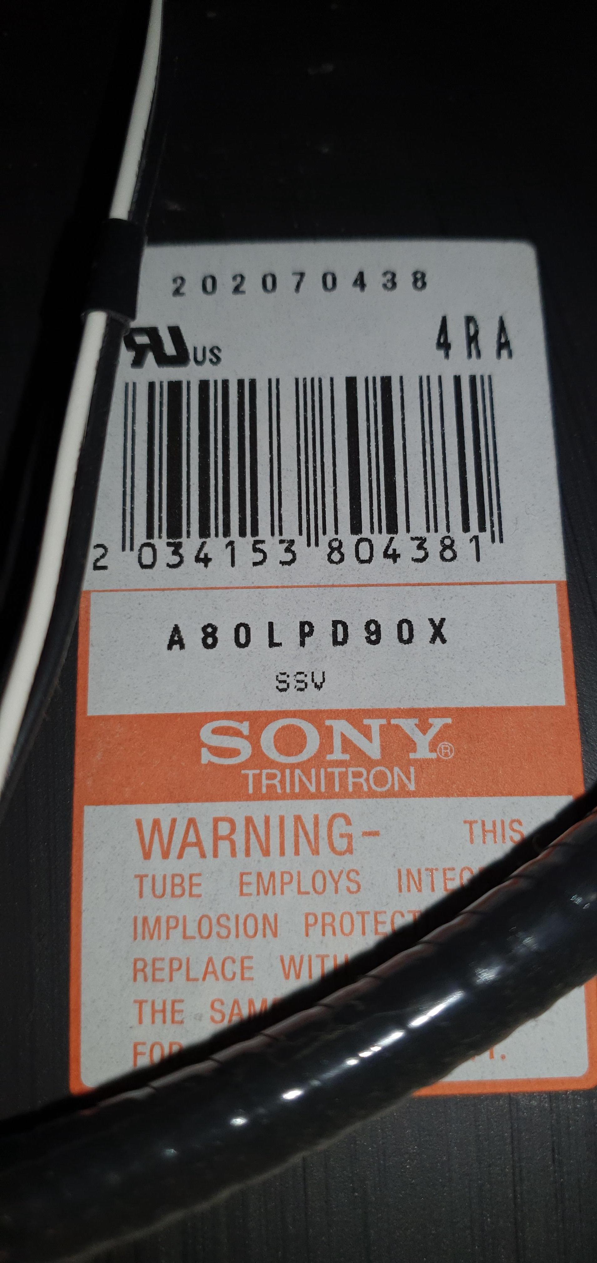
- Tube: Sony Trinitron A80LPD90X
- Jungle Chip: Sony CXA2159S
- OSD Chip: Sony CXP750097-032S
- Screen Size: 34"
- Power: 185 W
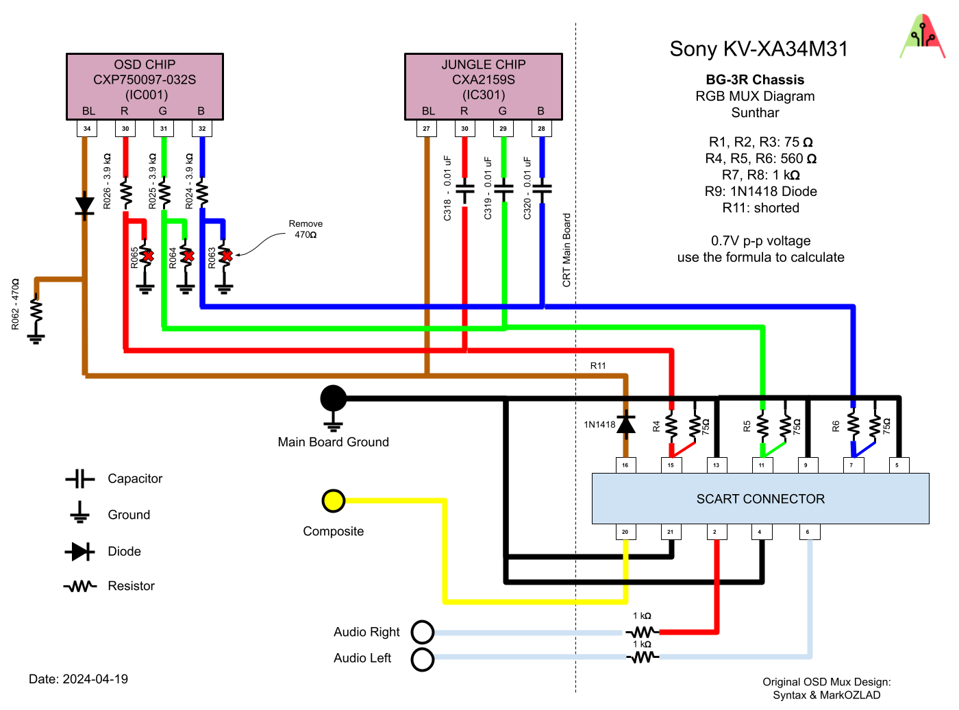
RGB mux diagram
Prepare the mux diagram. If you are building your own circuit, this diagram should help.
Performing the mod
Now that you roughly know what needs to be done, prepare for the mod. Place the board on a comfortable place. Make sure you are not putting pressure on the flyback or other components. Taking out the chassis is fairly straight forward on this CRT. There are few wires that needs to be disconnected.
- Degauss wire
- Power wire
- Ground wire attached to the neck board
- Yoke deflection coil wire
- Anode wire (this is the one with the rubber cap)
- Left and right audio wires
Please remember that wires 1-5 are critical for the CRT to function and should not be omitted. Having any of these wires disconnected while powering up can damage the board and can have adverse effects.
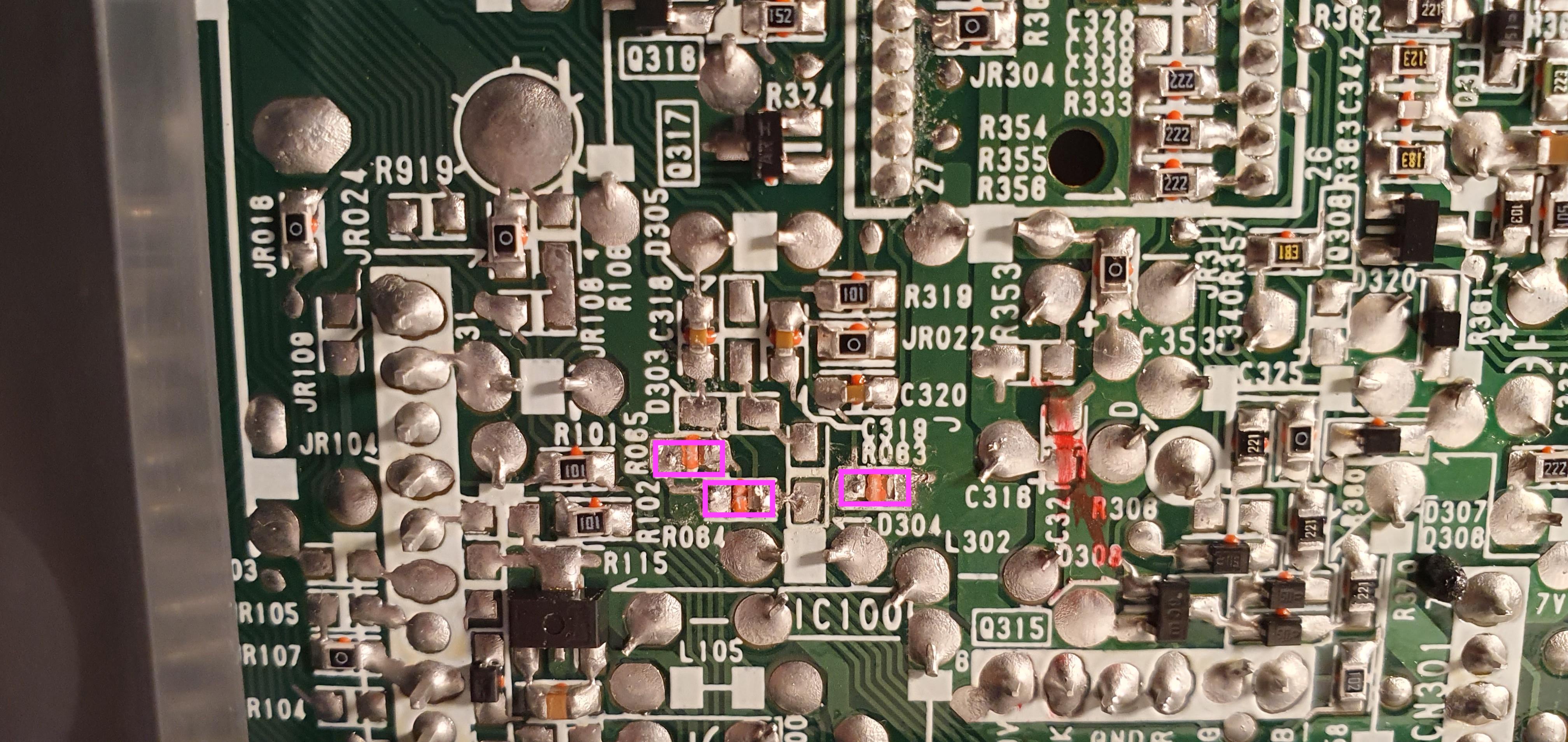
It should also be noted, the B board (smaller board) should be removed to solder audio, sync and ground. The A board (bigger board) doesn’t need to be removed but does need to be on its side so you can remove the R063, R064 and R065 resistors.
Mux diagram
STEP 1: Remove the following components
Closed caption card (teletext) and OSD shares the same RGB input on the chroma. Therefore, this is not going to be a direct injection. It still requires the removal of the three (470Ω) ground resistors on the OSD side.
- R063 (470Ω)
- R064 (470Ω)
- R065 (470Ω)
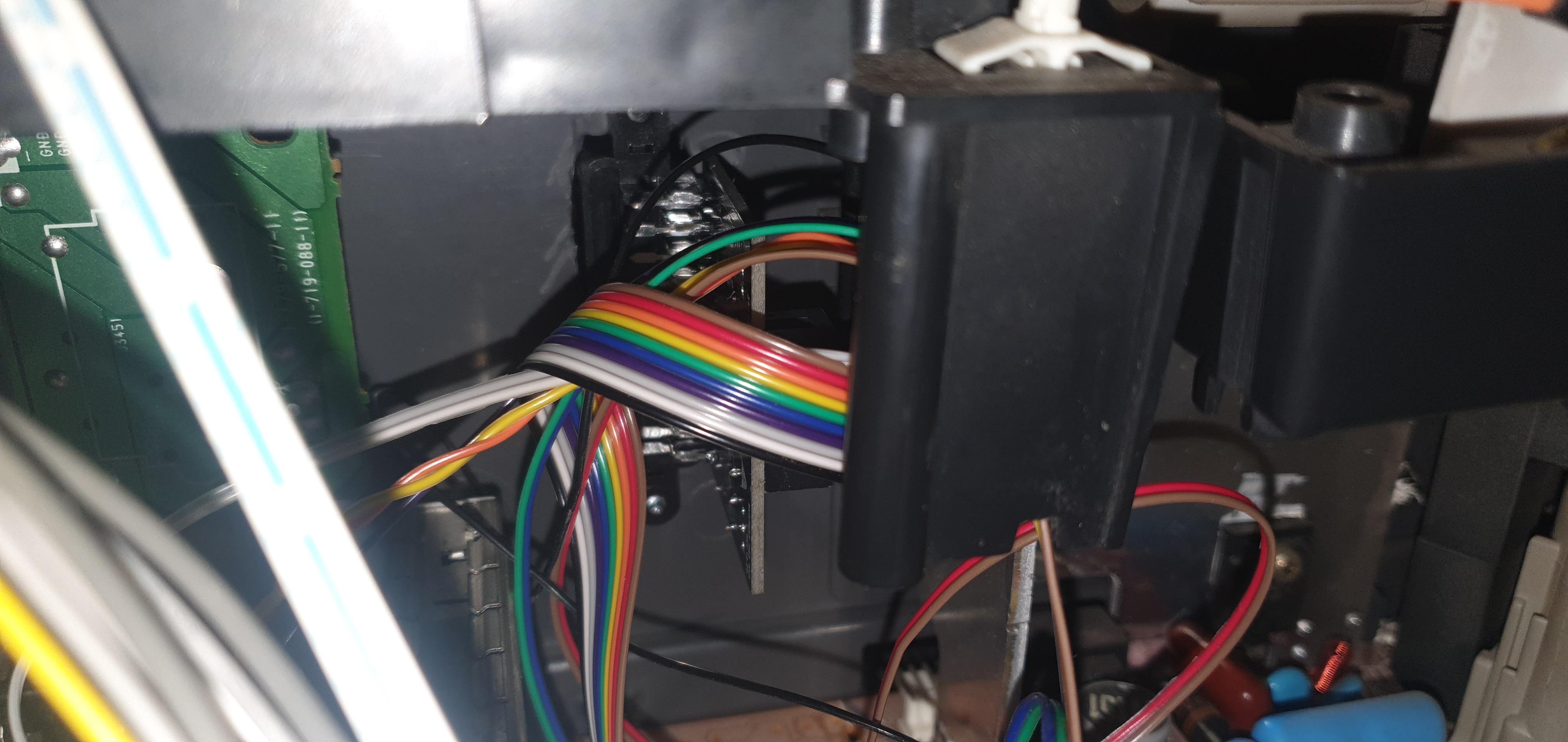
STEP 2: Connect RGB, Blanking and Ground
We are going to get rid of the closed caption (teletext) card and tap into the RGB input there.
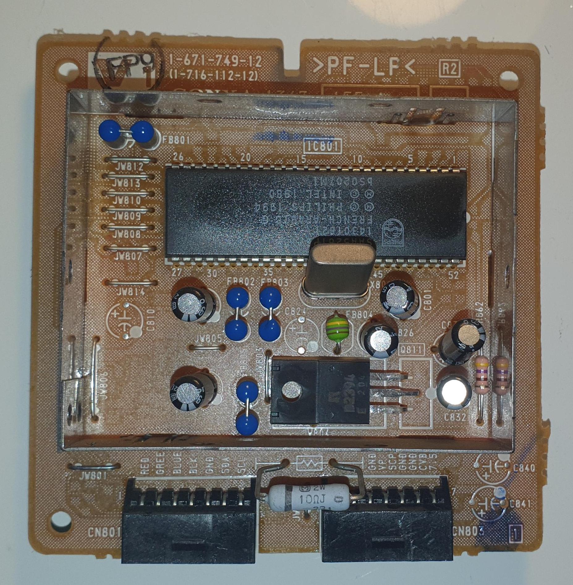
The CN801 connector was salvaged. 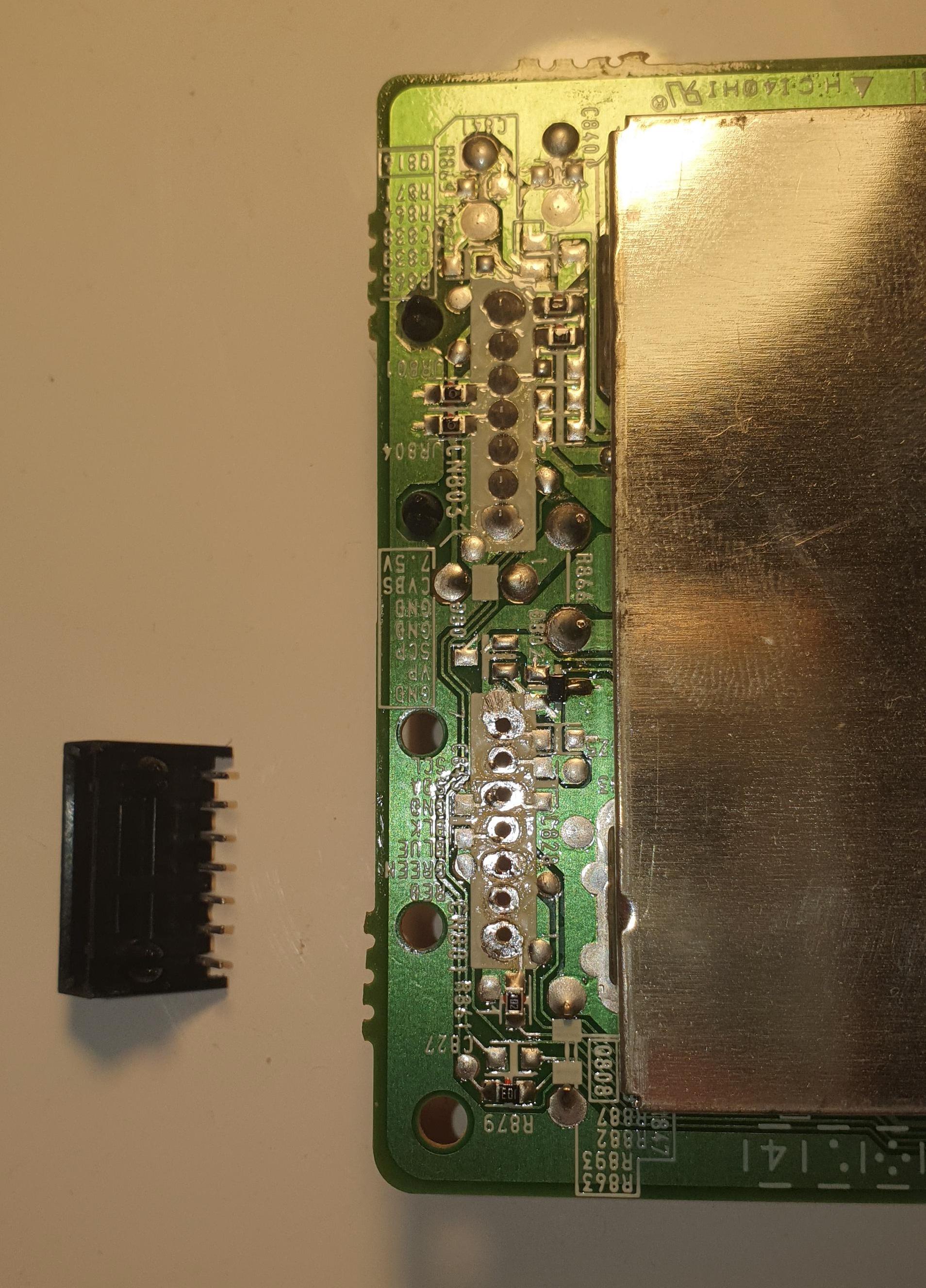
R, G, B, Blanking and Ground wires were soldered to this connector. 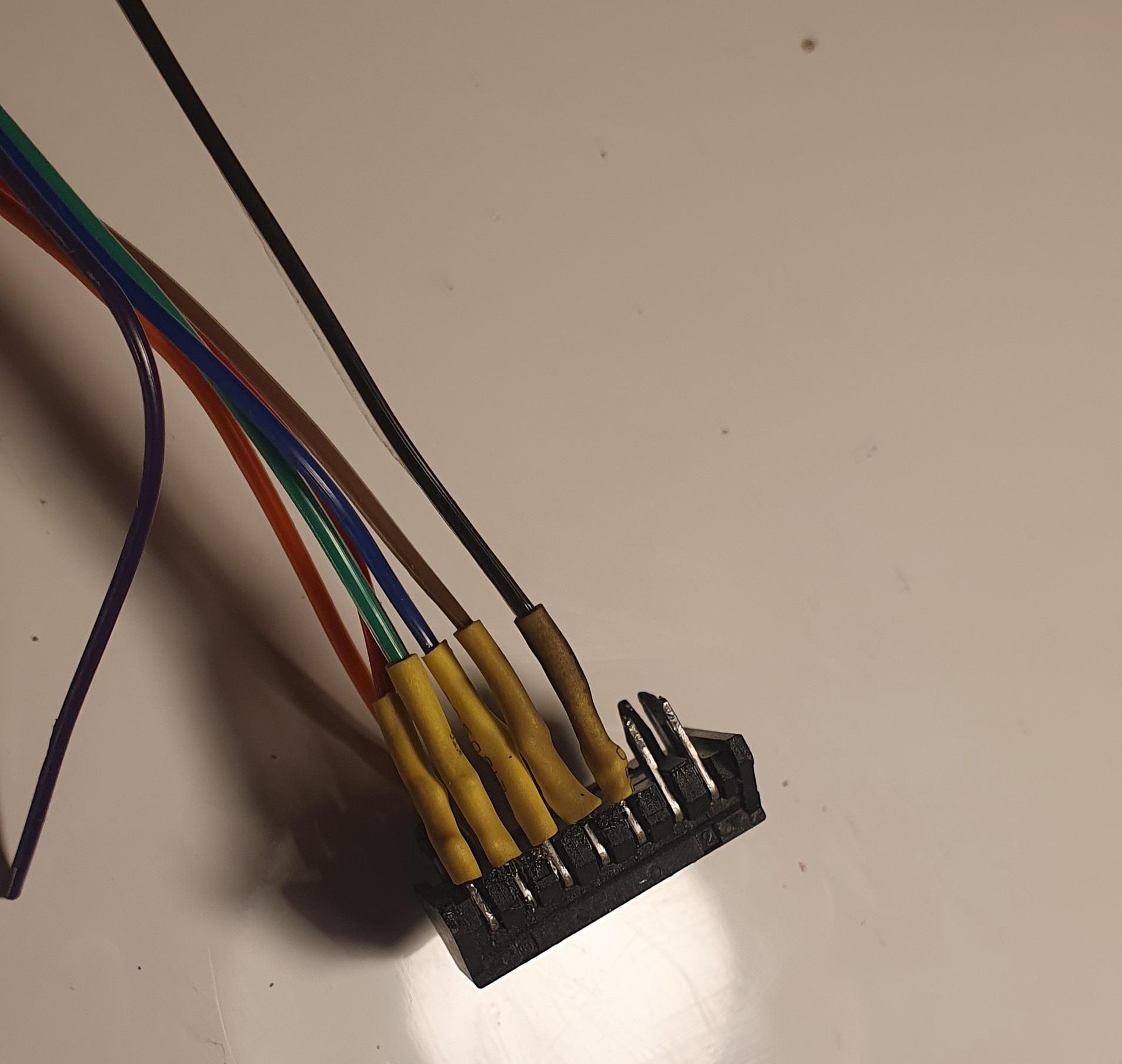
The connector was reinserted into the board. 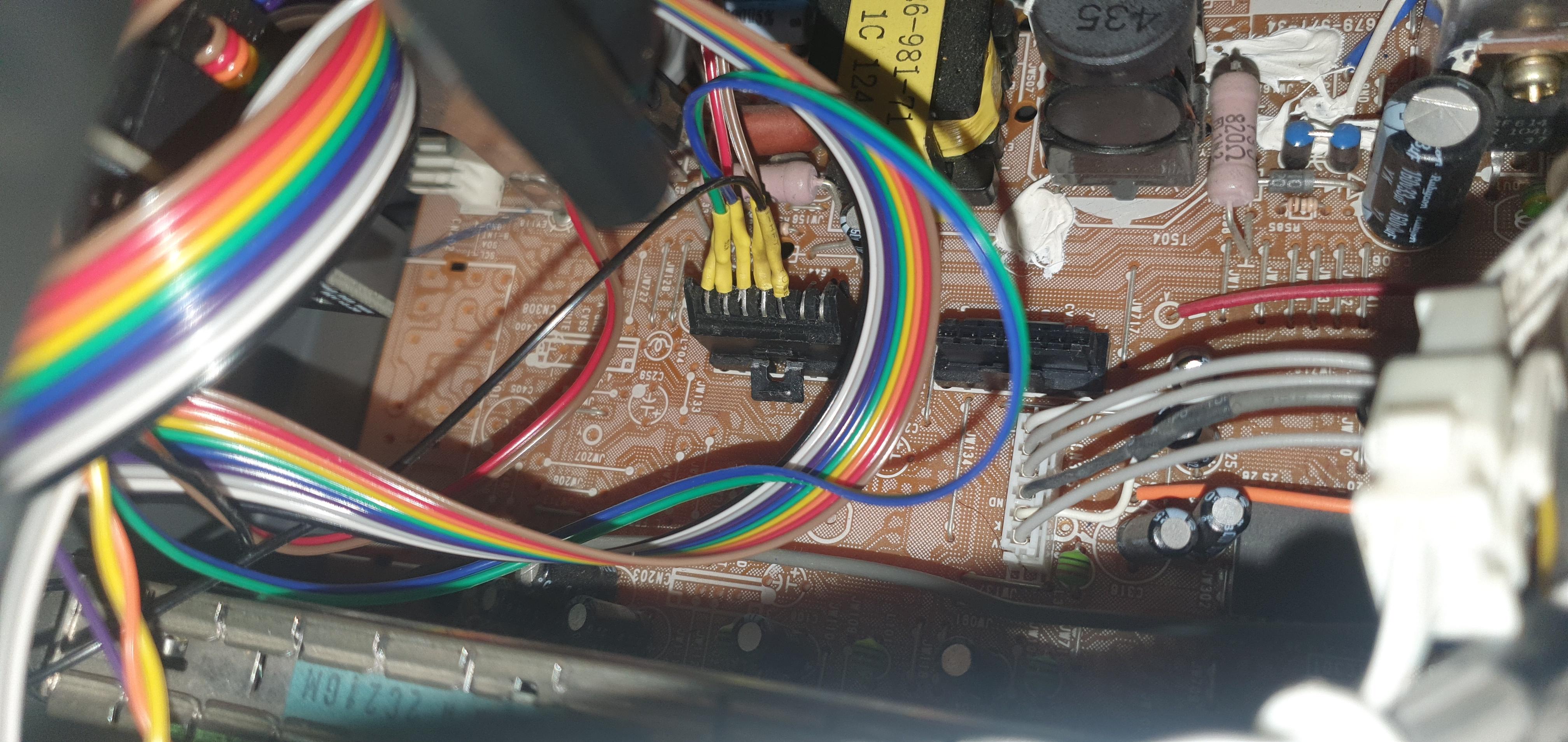
STEP 3: Connect Audio and Sync
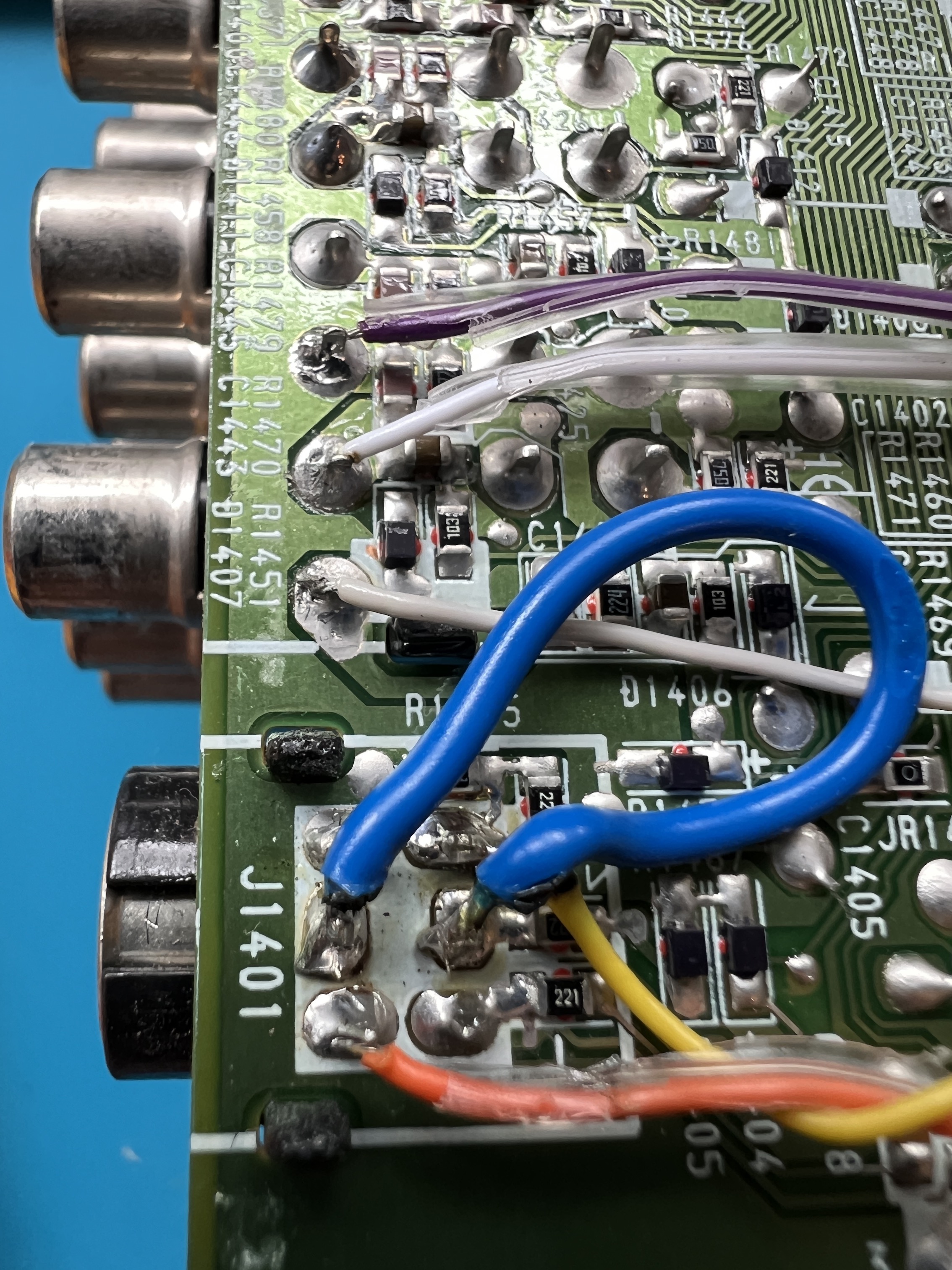
Soldered sync to the S-Video luma pin. 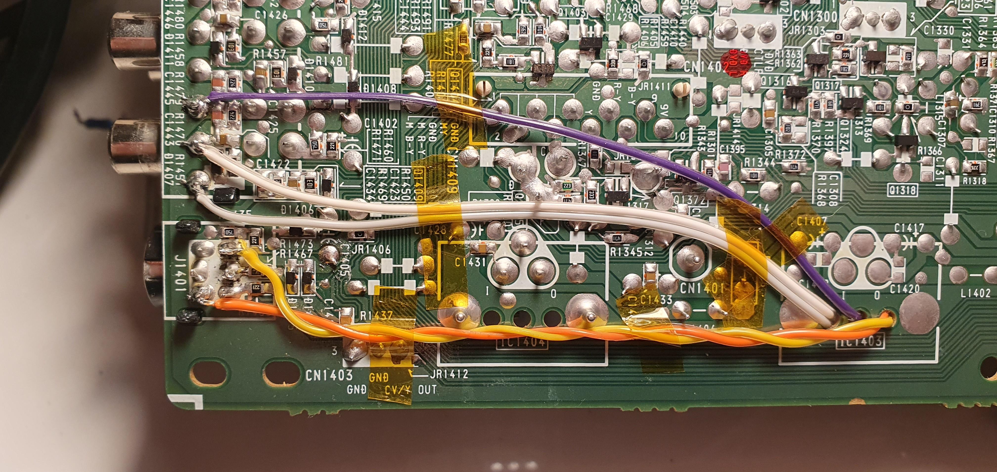
Note: S-video and audio dummy plugs are required for sync and stereo audio.
To permanently enable the luma input, you can follow the method Aidan Carter used on his Sony KV-XA25M31 set. In this setup, the blue wire connects the S-Video detect pin directly to ground. This effectively disables the composite input linked to the S-Video line. However, for most people with multiple composite inputs, this won't pose a significant issue.
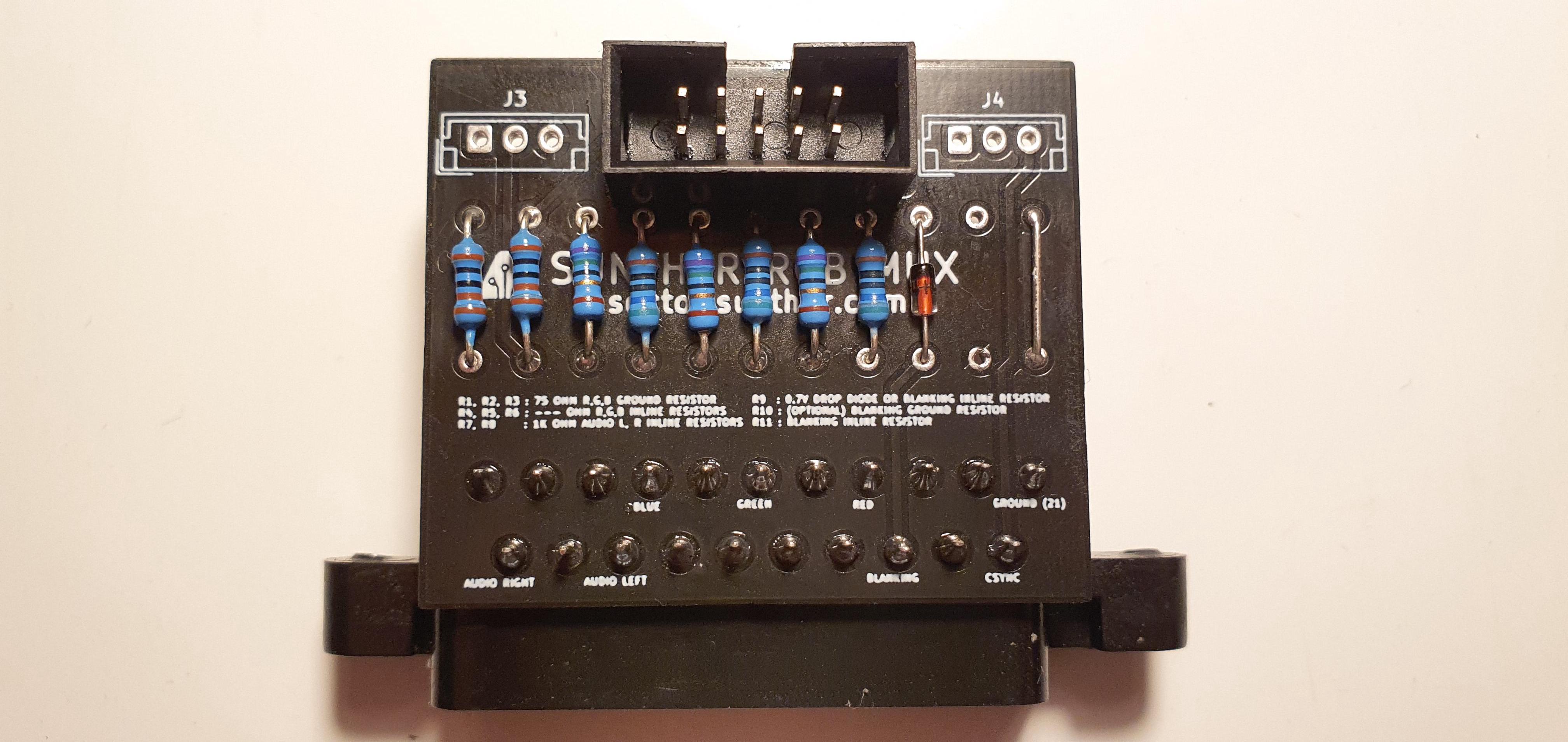
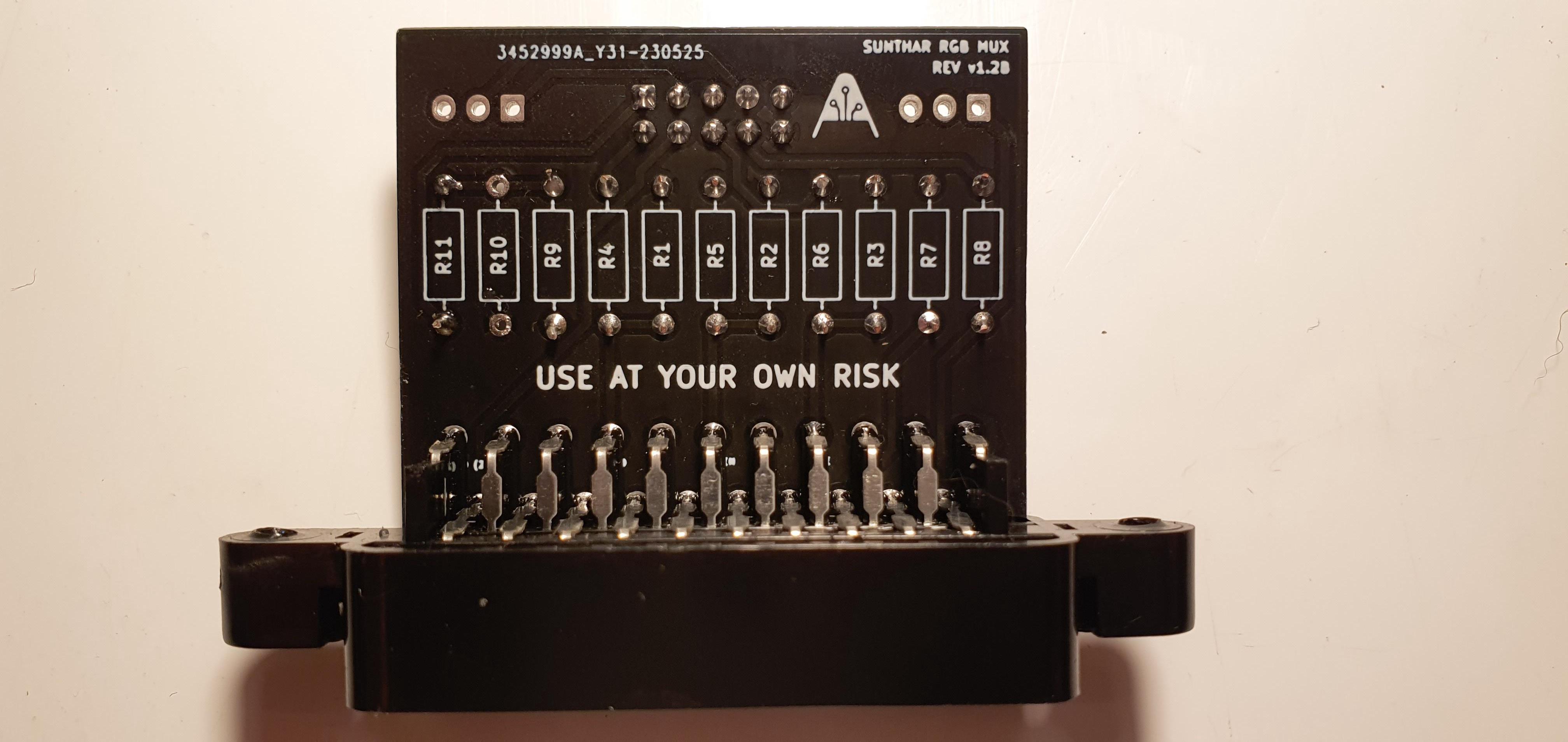
STEP 4: Build your mux board
This mod uses the RGB mux board. This is optional, but will make your mod easier and stable. You can also create the circuit presented in the schematics above without the board. Please also checkout the mux calculator to play with your own values.
| On Sony CRT Chassis | KV-XA34M31 |
|---|---|
| CRT RGB inline resistor | 3.9kΩ |
| CRT RGB ground resistors removed | 470Ω |
| 0.1μF caps replaced | No |
| Add diodes on chassis RGB lines? | No |
| Add blanking diode on chassis | No |
| RGB mux board | KV-XA34M31 |
|---|---|
| Mux board RGB termination (R1, R2, R3) | 75Ω |
| Mux board RGB inline resistors (R4, R5, R6) | 560Ω |
| Mux board blanking diode (R9) | 1N4148 |
| Mux board blanking ground resistor (R10) | open |
| Mux board blanking resistor (R11) | short |
Compatible mux boards:
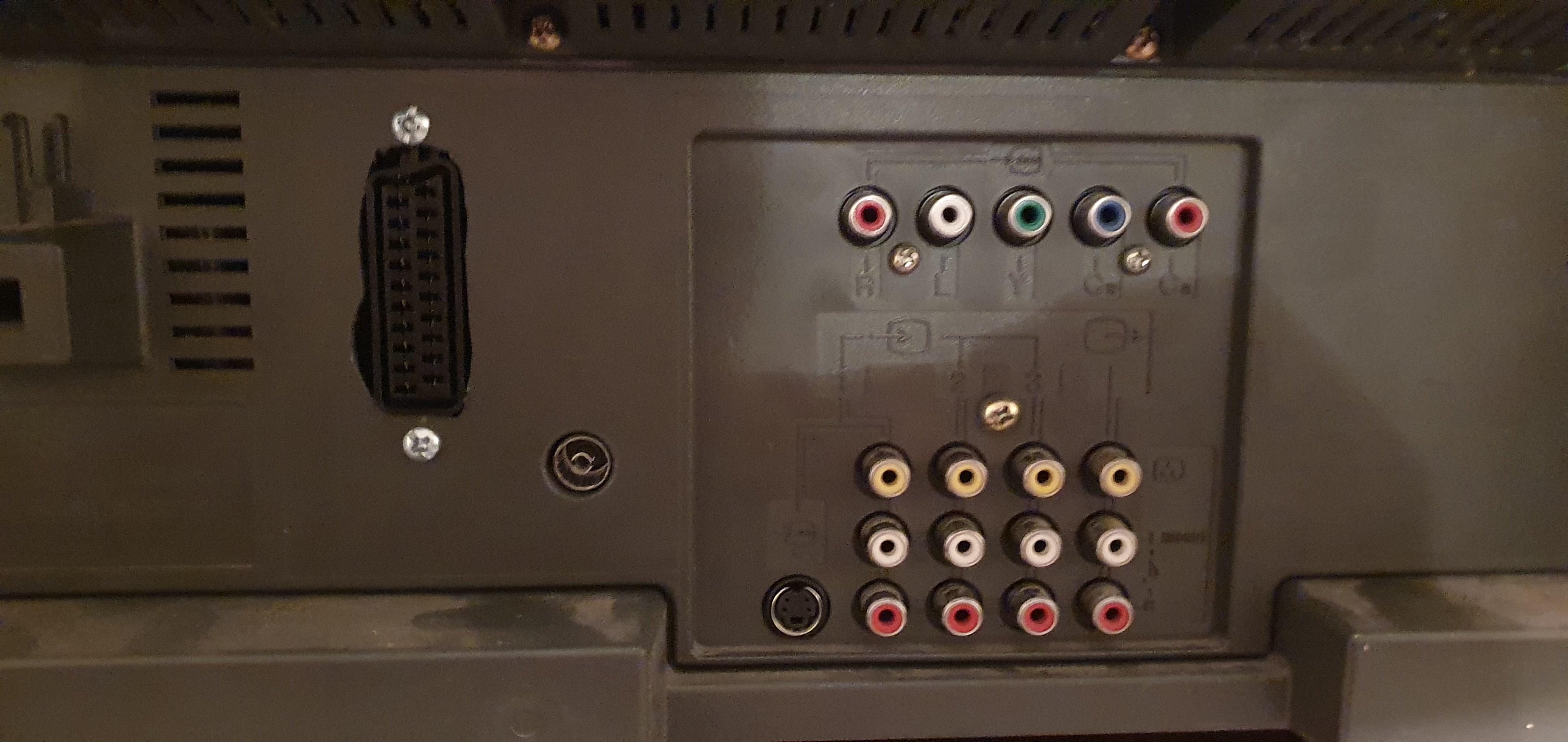
STEP 5: Attach the female SCART connector to TV
Creating a SCART cutout and mounting it is an art. I have a dedicated section for it. How to create and mount a SCART female plug?
This SCART port was cut a bit rough. You can make the SCART port look smoother with a file. 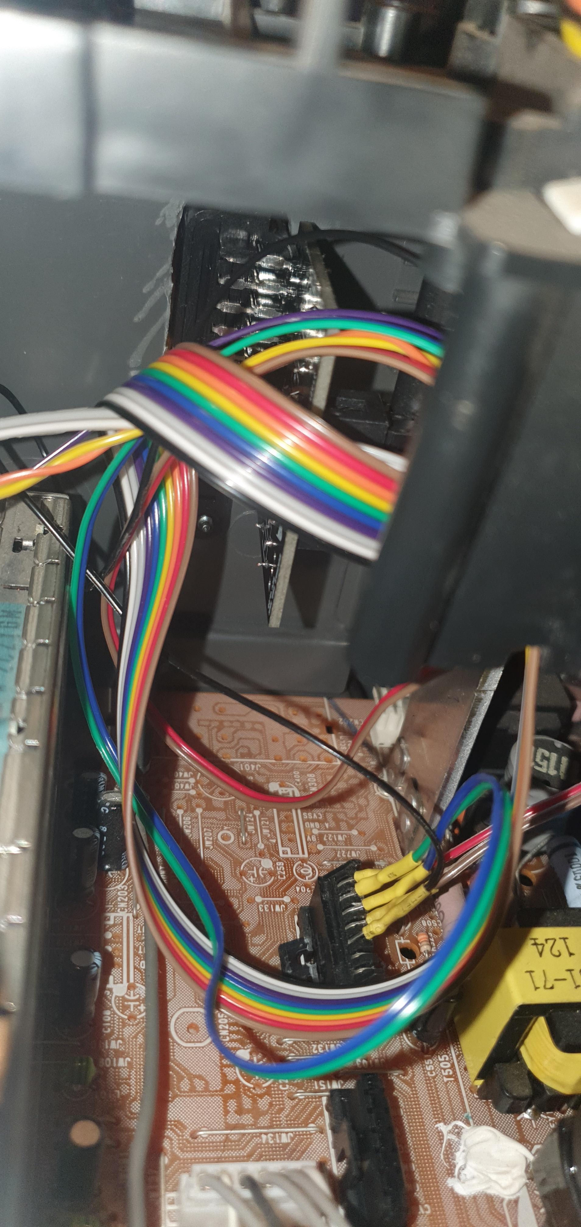
Horizontal Position Adjustment
In some cases, especially on larger screens, the picture will not be centered even after adjusting HPOS to 0 or to its maximum value. To get around this, you can try adjusting this lever, which will shift the picture horizontally. 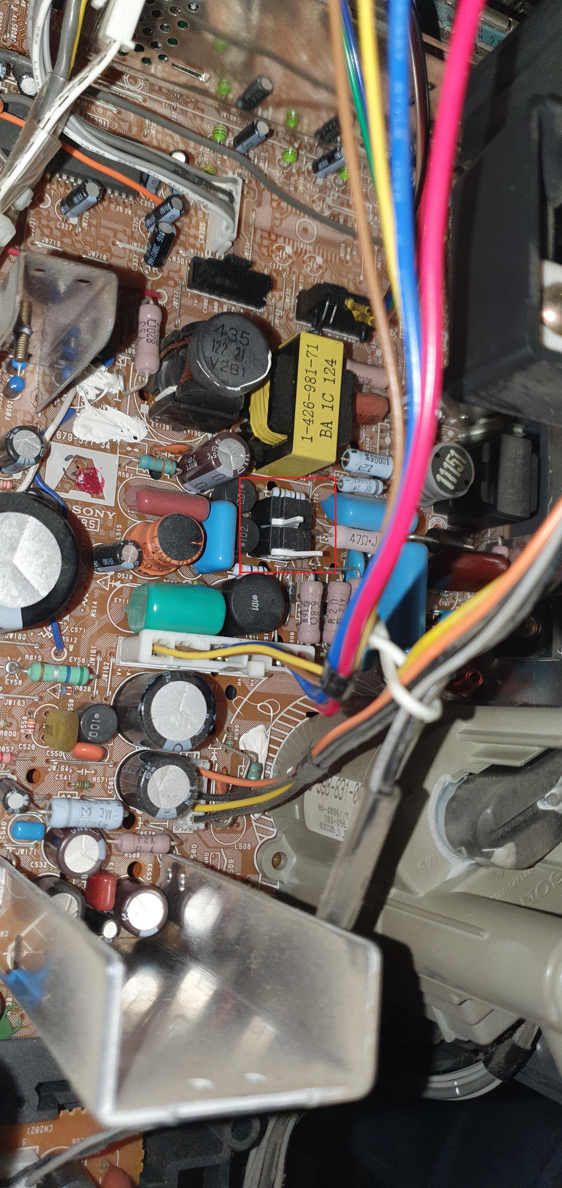
Games
Spyro The Dragon 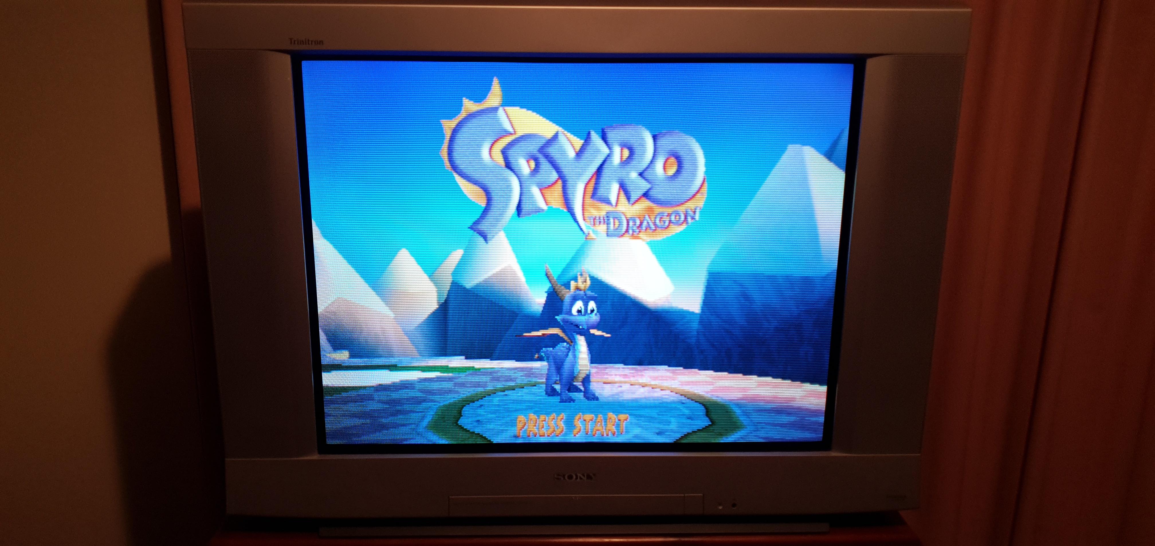
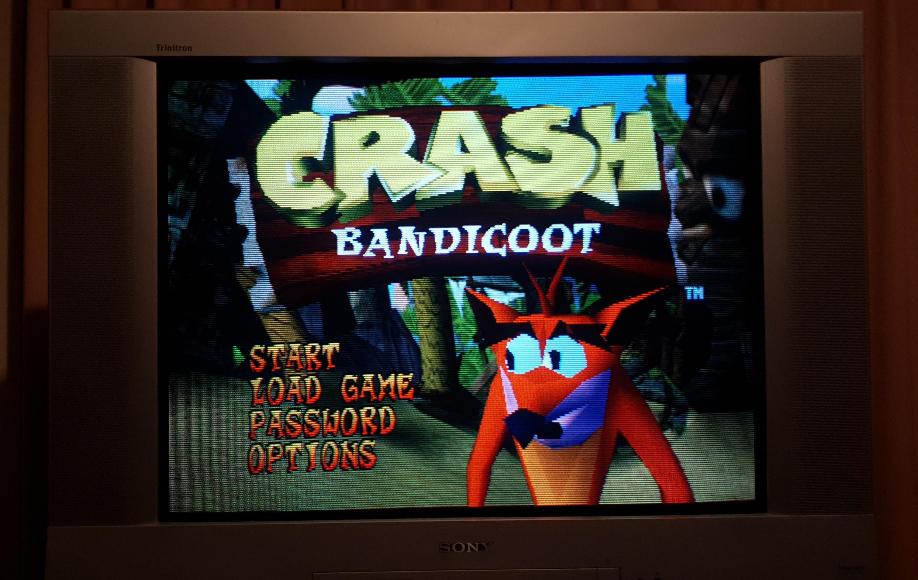
Crash Bandicoot
Patterns
240p - SMPTE 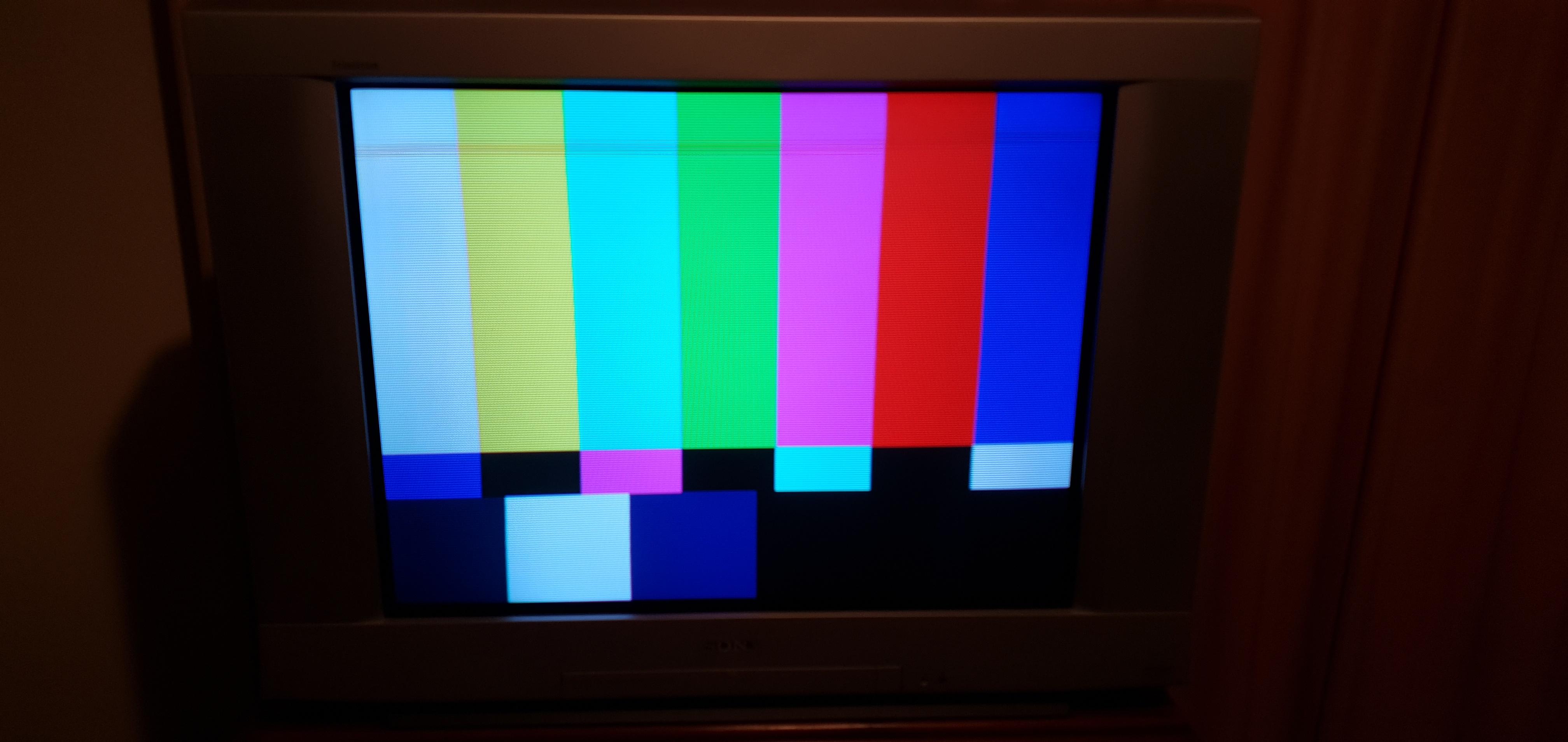
240p - Pluge 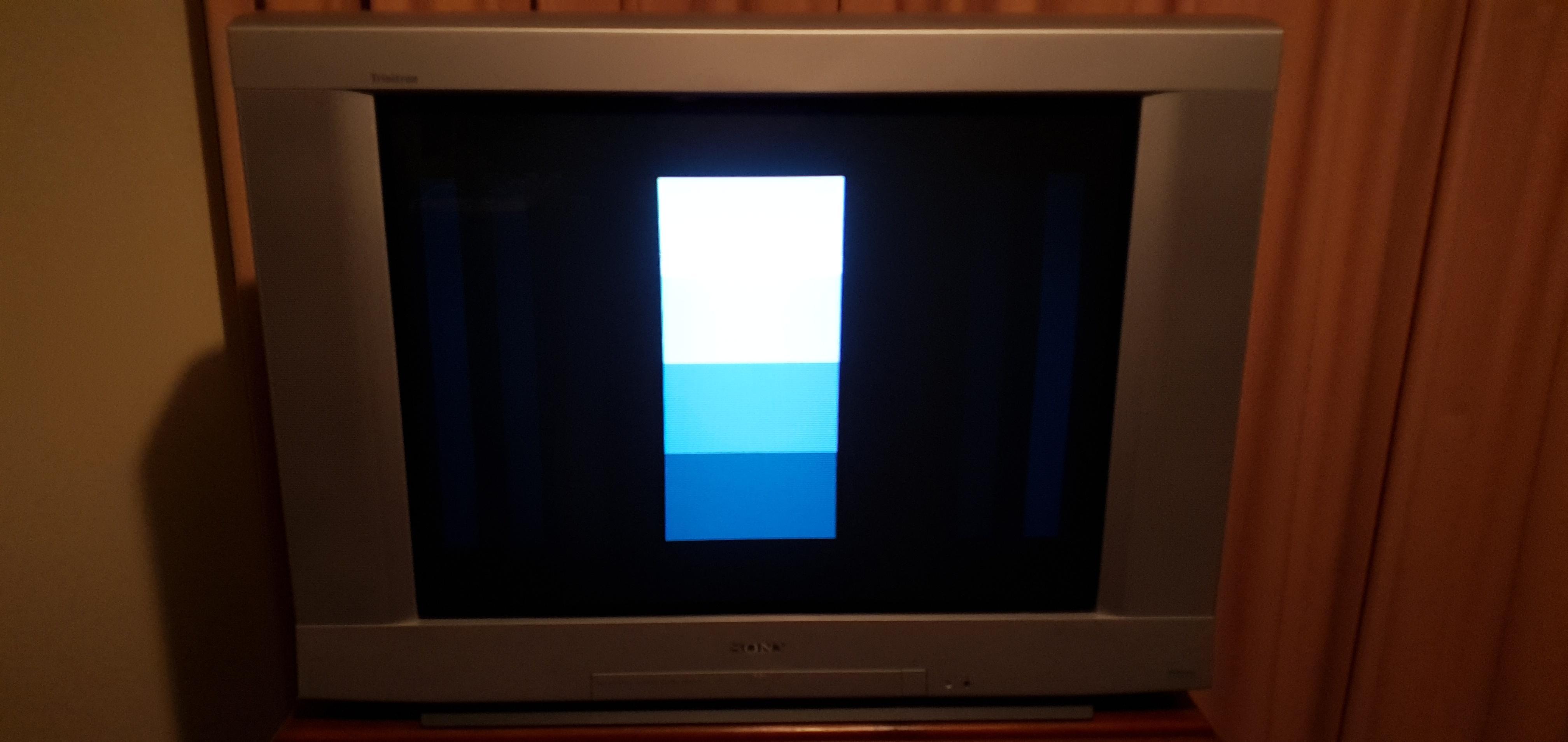
240p - Grid 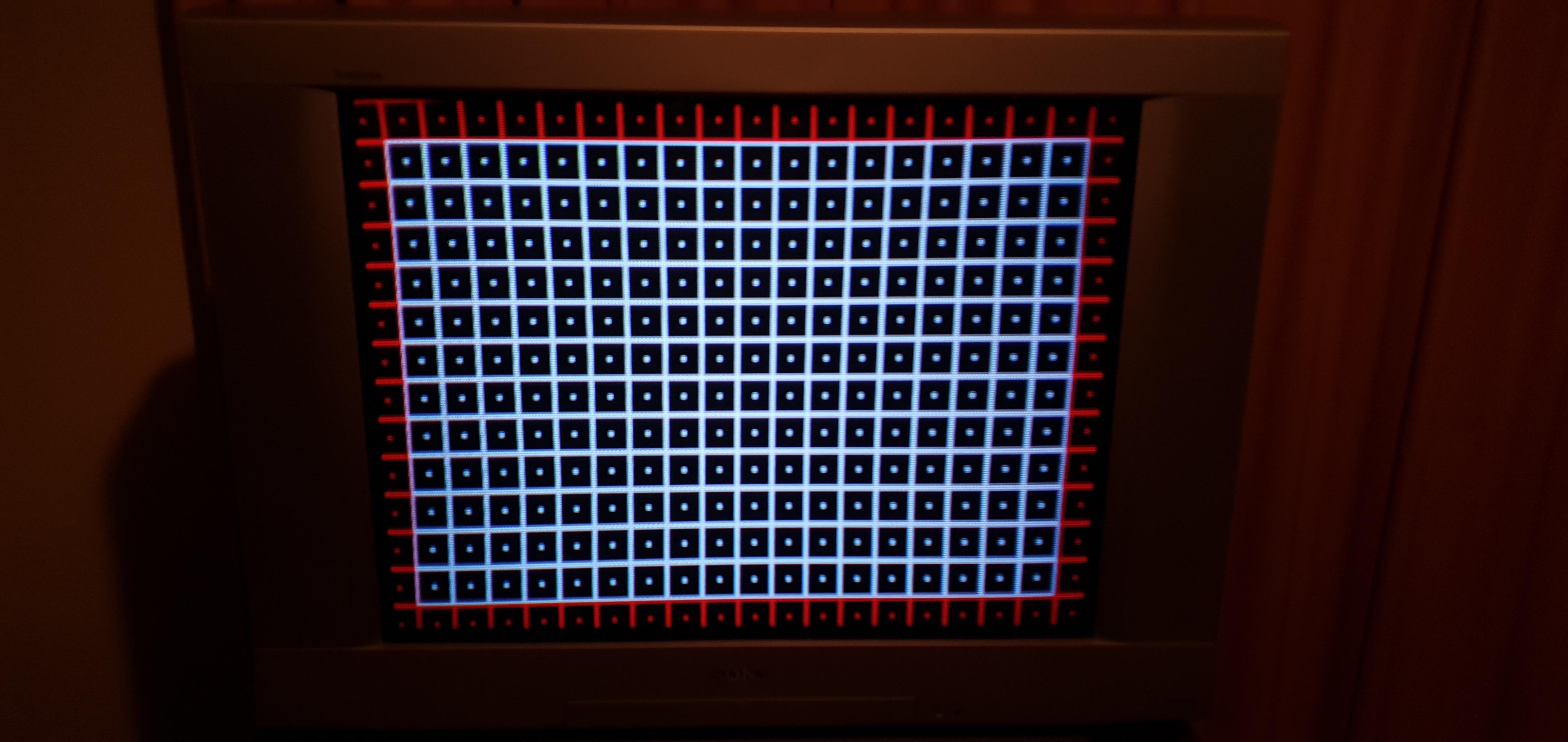
240p - RGB 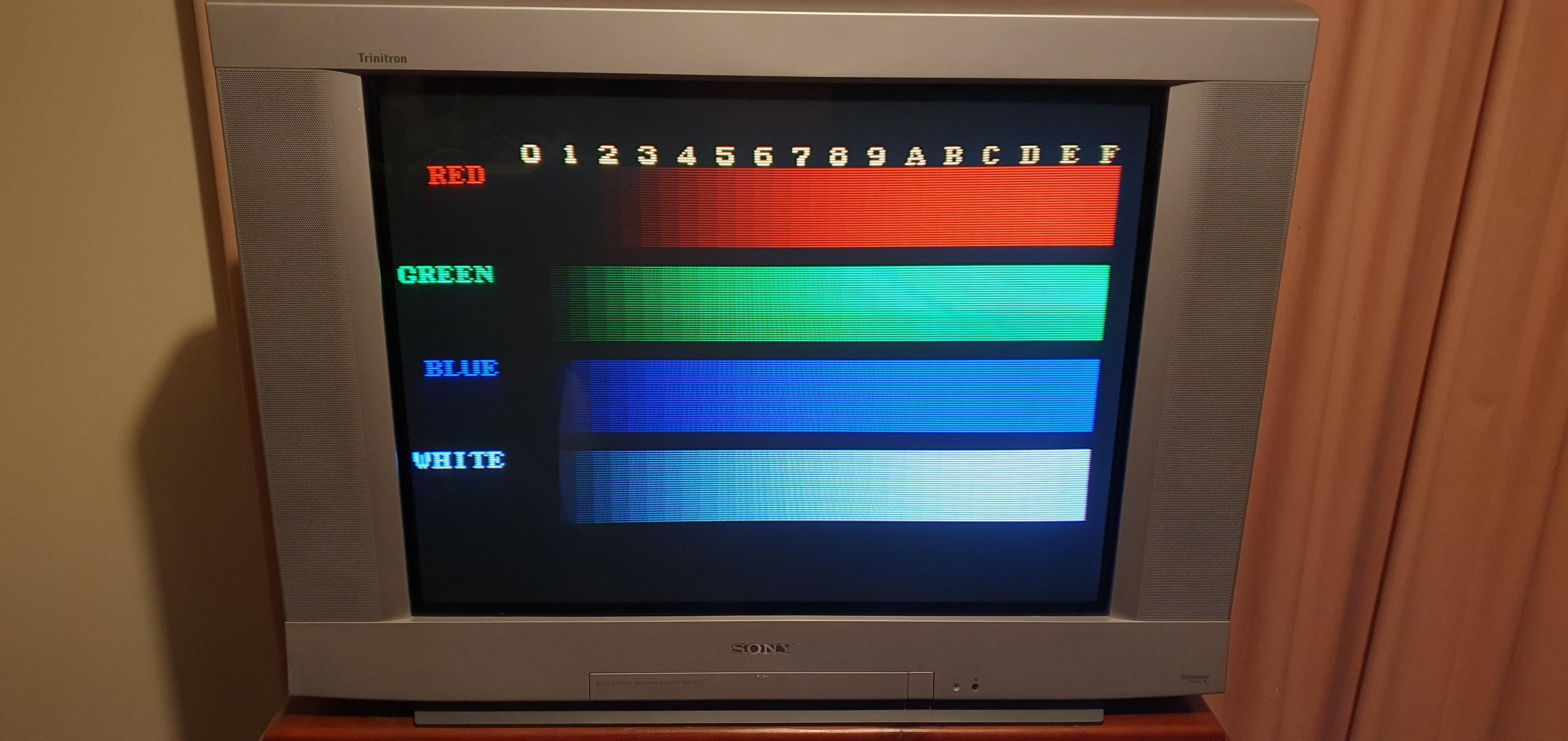
TV off 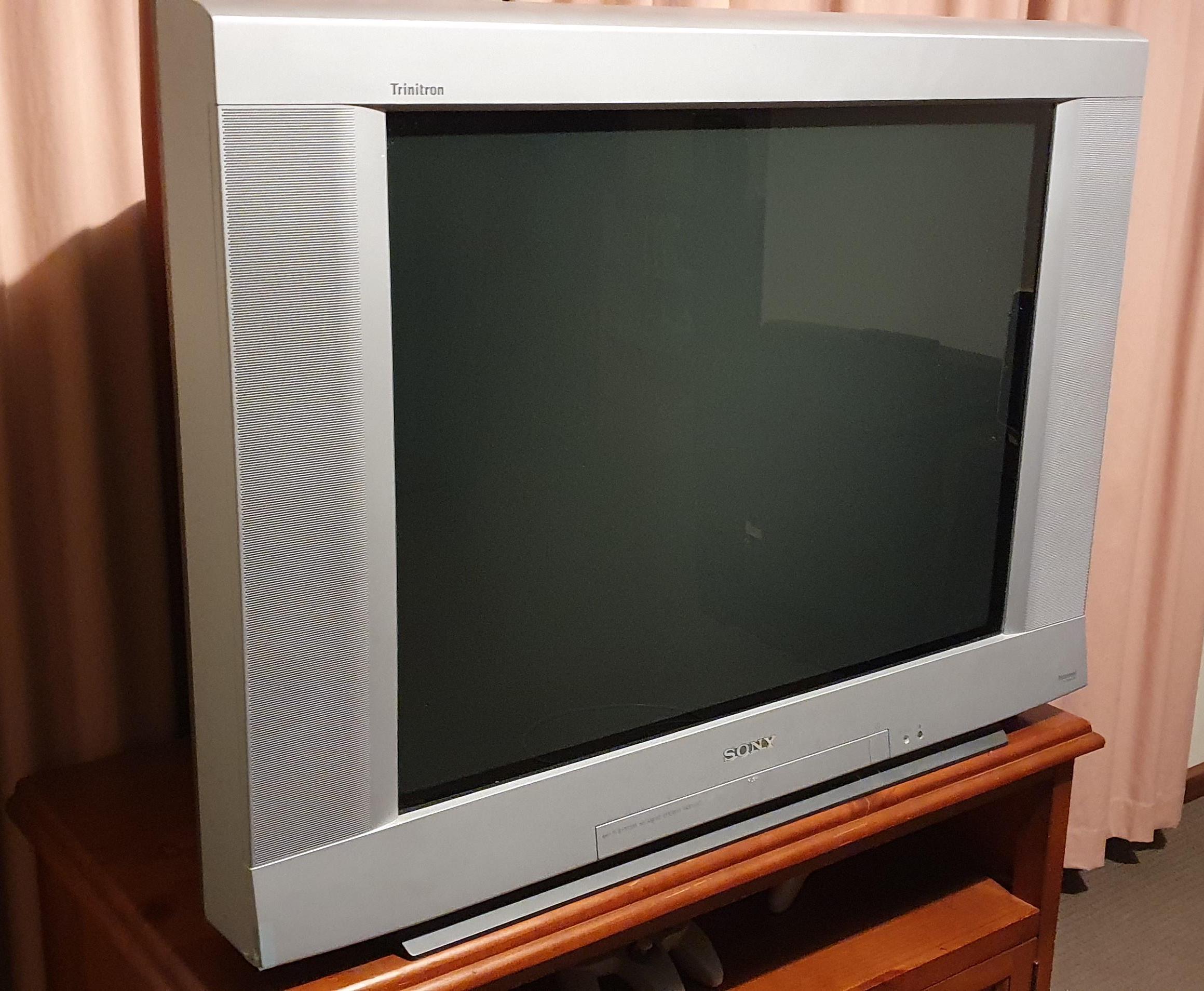
B Board 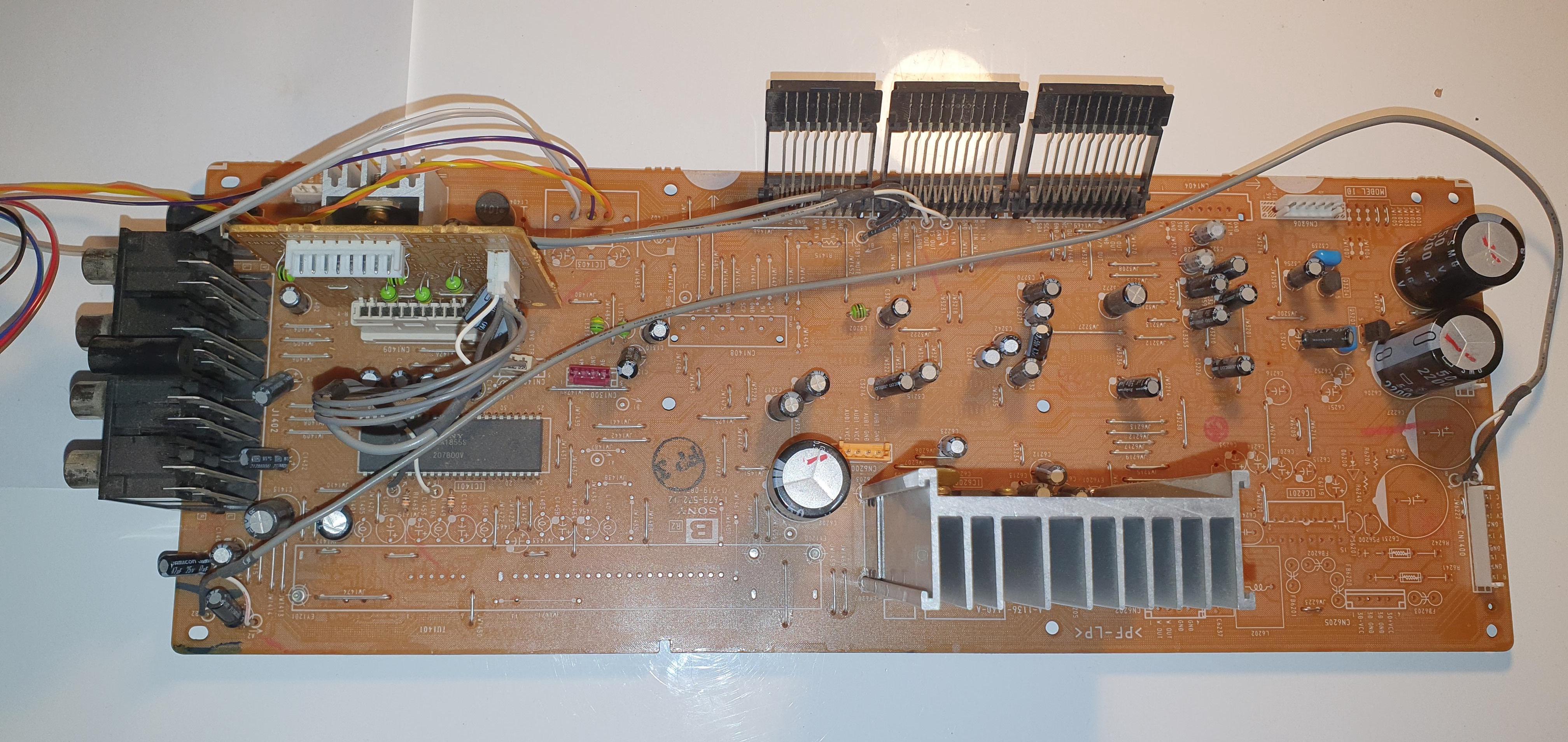
A & B Boards 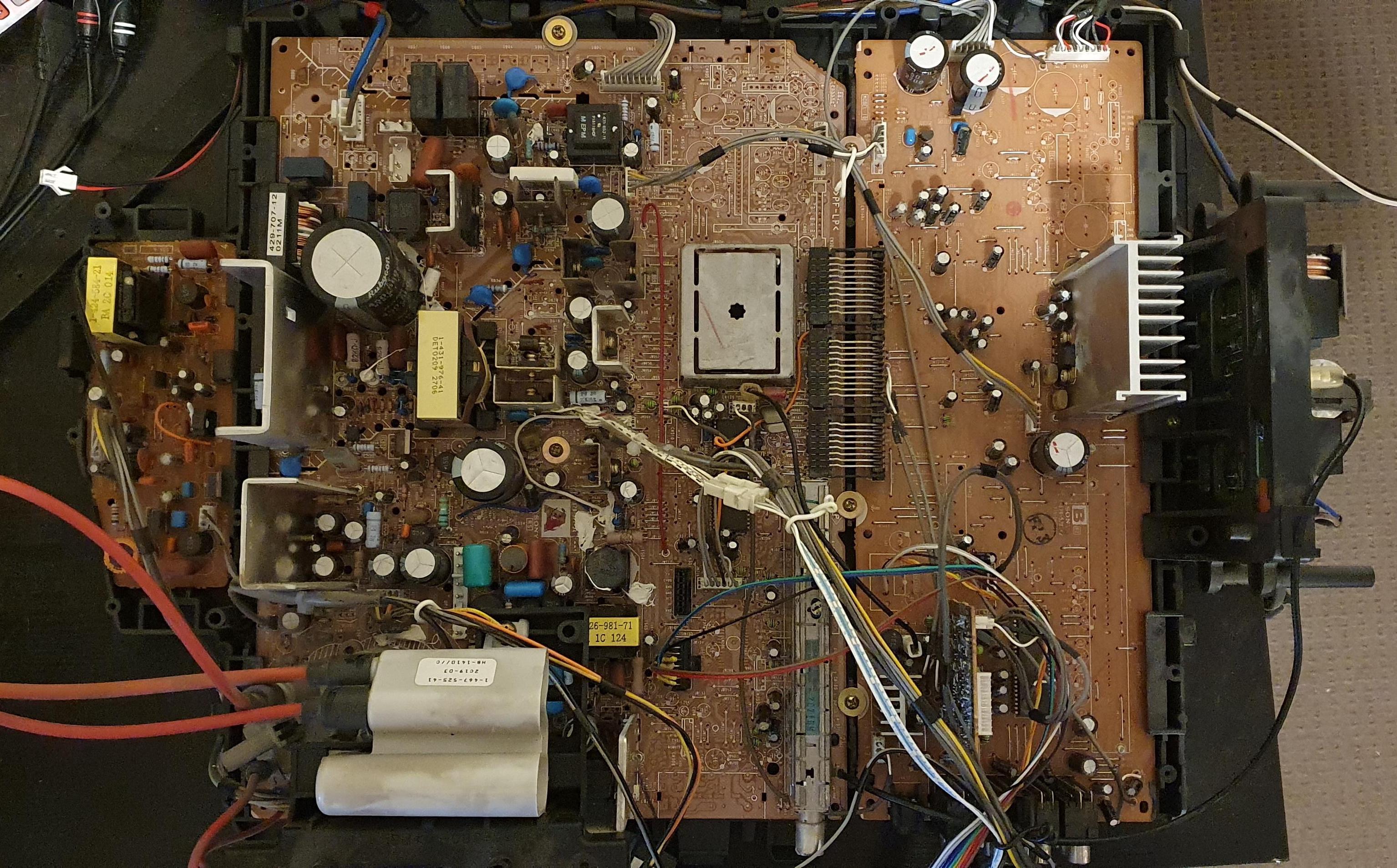
Back Label 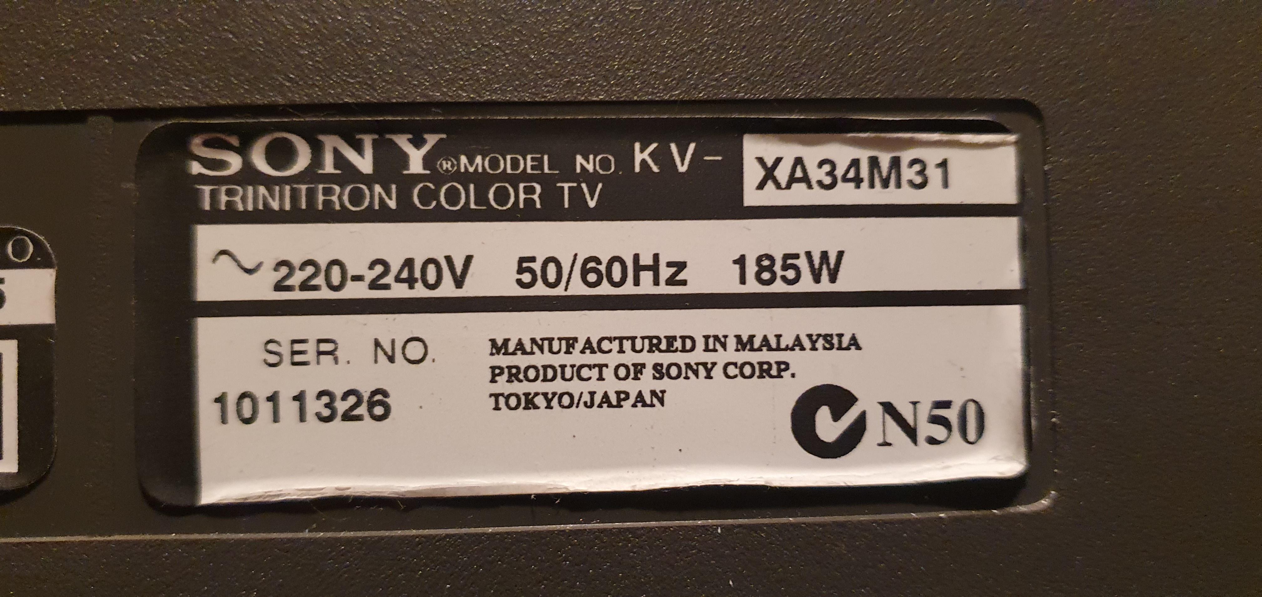
Tube