Toshiba 27A34
Toshiba 27A34 CRT RGB mod
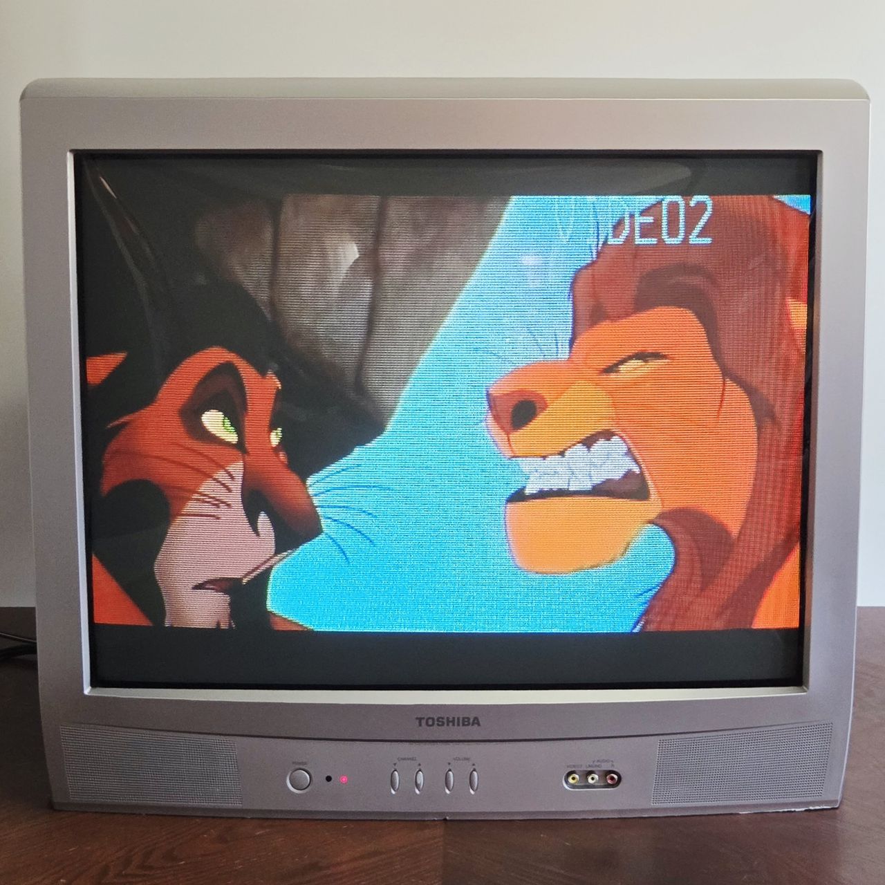
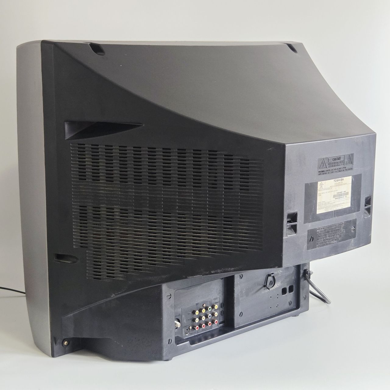
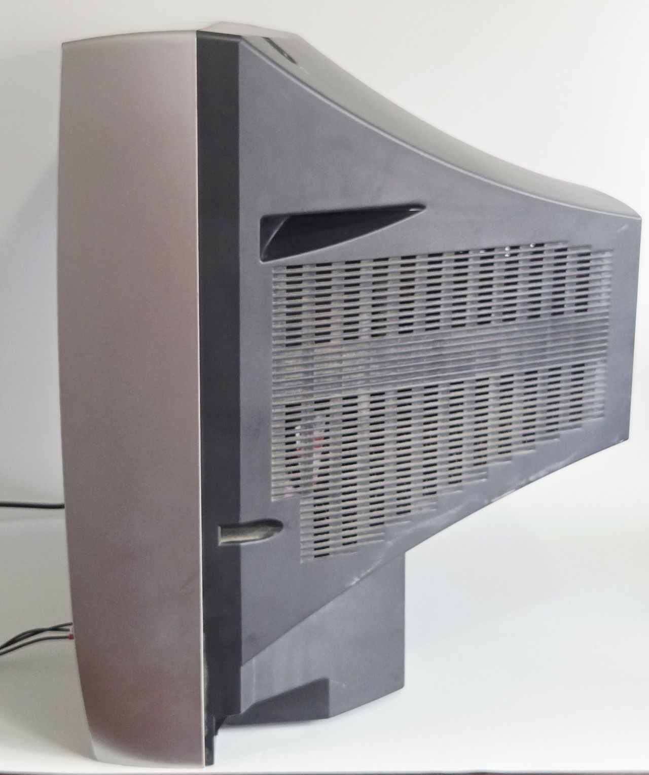
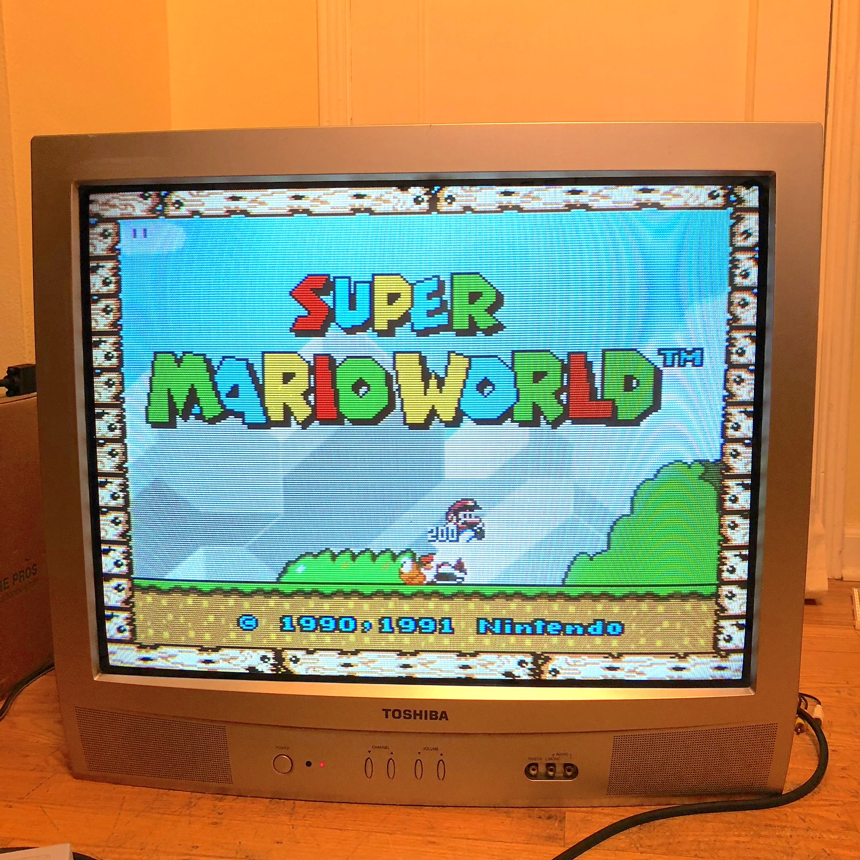
The Toshiba 27A34 is a 27" curved CRT television released in the mid-2000s. Its curved screen provides excellent geometry and sharp picture quality. The television features component video inputs and allows users to check the number of hours the tube has been in use, provided the counter has not been reset. This model offers superior geometry and reduced distortion compared to flat-screen alternatives and is RGB modifiable.
View full CRT details and more mod examples →
Table of Contents
Contributors
Thank you to everyone who contributed to this guide:
- Kaz Packman — contributor, RGB mod and pictures
CRT safety
Caution
You can die doing this! So read carefully! CRT TV is not a toy. Do not open a CRT TV. If you don't have any prior knowledge about handling high voltage devices, this guide is not for you. CRT TV contains high enough voltage (20,000+ V) and current to be deadly, even when it is turned off.
Plan of attack
Manuals and Datasheets
Specs
- Manufactured: Thailand (2004)
- Chassis: M3N425
- Jungle Chip: Renesas M61283FP
- OSD Chip: Orion OEC7090A
- Screen Size: 27"
- Power: 125 W
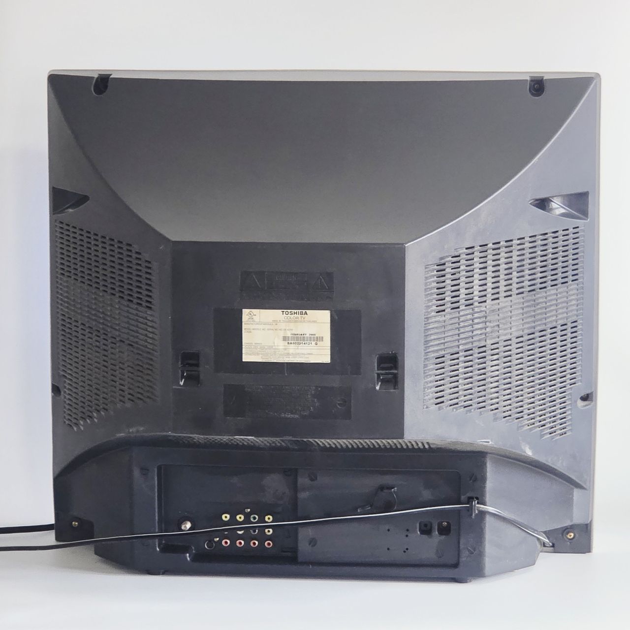
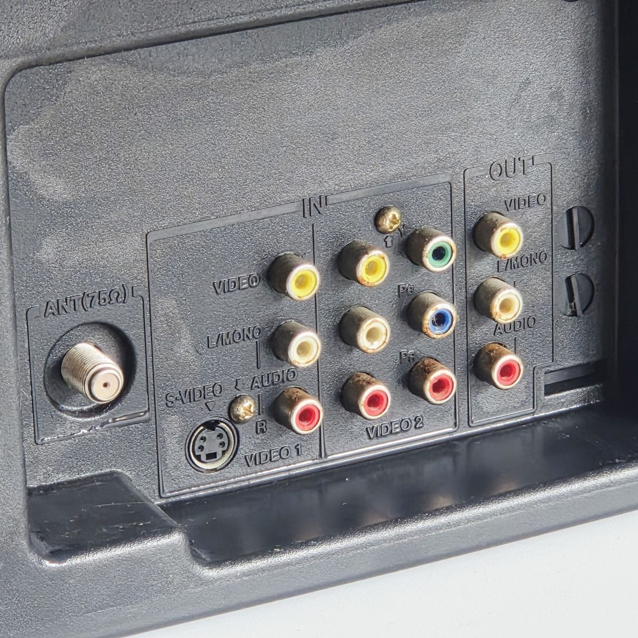
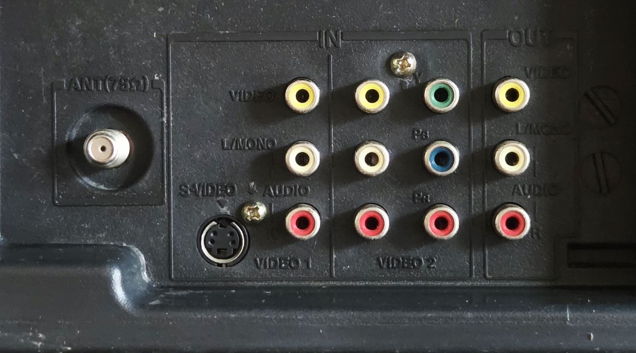
- Inputs: RF, Component YPbPr, Composite, S-Video
RGB mux diagram
Prepare the mux diagram. If you are building your own circuit, this diagram should help.
Performing the mod
STEP 1: Remove the grounding resistors and capacitors
Remove the three 820Ω RGB resistors to ground
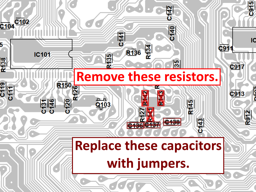
OSD grounding resistors R141, R142, and R143 should be removed. The inline capacitors C136, C137, and C138 should be removed and replaced with jumpers. I forgot to take a photo of the chassis for this step, but the diagram attached shows where the components are located on the chassis.
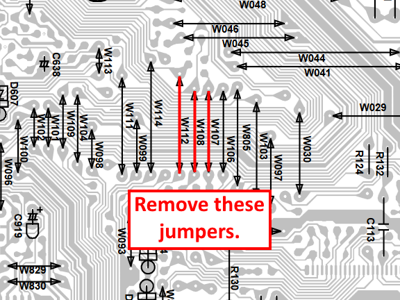
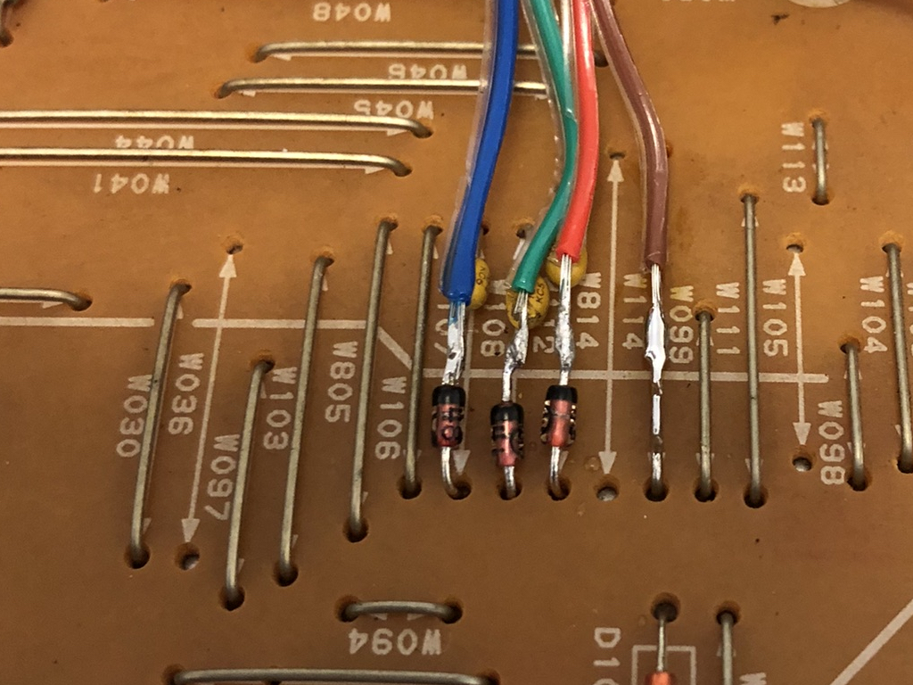
STEP 2: Replace jumpers with capacitors and diodes, then connect RGB and blanking
Remove jumpers W107, W108, and W112 from the chassis and replace them with 1N4148 diodes and 0.1uF ceramic capacitors. Picture below illustrates the direction of these components as well as where the RGB lines should be connected. Pay attention to the direction of the diodes. The blanking wire (brown) should be connected to jumper W114.
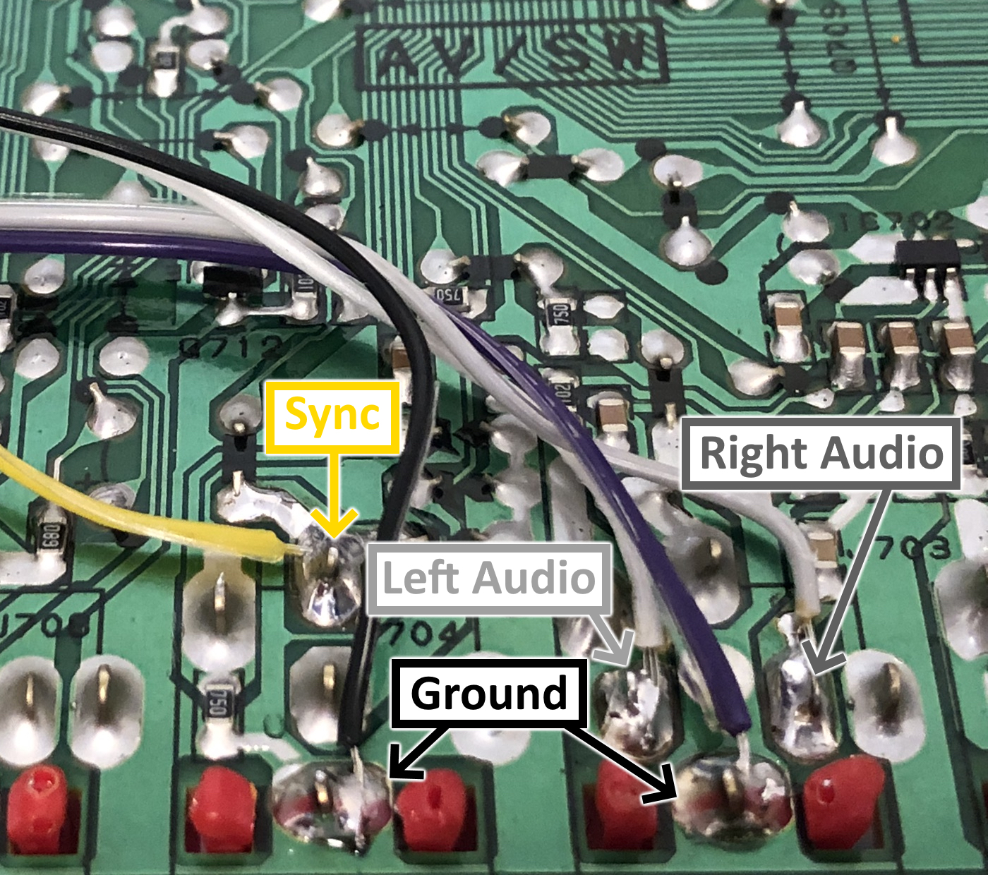
STEP 3: Connect sync, ground, and audio
Sync should be injected to the Component Luma (Y) input and audio goes to its respective audio lines. See the attached photo for the location which the wires should be connected to.
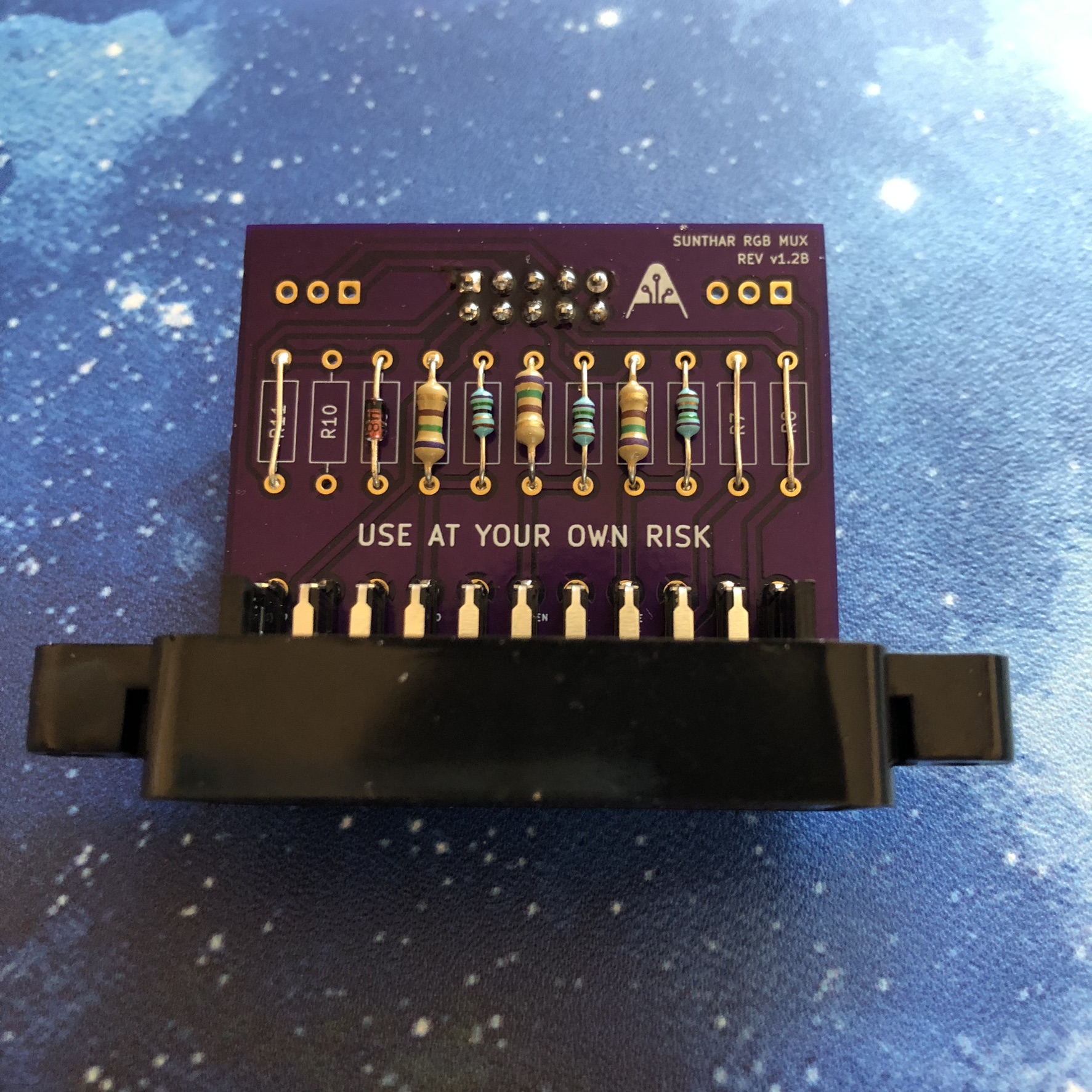
STEP 4: Build your mux circuit
This mod uses the RGB mux board. This is optional, but will make your mod easier and stable. You can also create the circuit presented in the schematics above without the board. Please also checkout the mux calculator to play with your own values.
| On Toshiba CRT Chassis | 27A34 |
|---|---|
| CRT RGB inline resistor | 3.9kΩ |
| CRT RGB ground resistors removed | 680Ω |
| 0.1μF caps replaced | Yes |
| Add diodes on chassis RGB lines? | Yes |
| Add blanking diode on chassis | No |
| RGB mux board | 27A34 |
|---|---|
| Mux board RGB termination (R1, R2, R3) | 75Ω |
| Mux board RGB inline resistors (R4, R5, R6) | 1kΩ |
| Mux board Audio LR (R7, R8) | 1kΩ |
| Mux board blanking diode (R9) | 1N4148 |
| Mux board blanking ground resistor (R10) | open |
| Mux board blanking resistor (R11) | short |
Compatible mux boards:
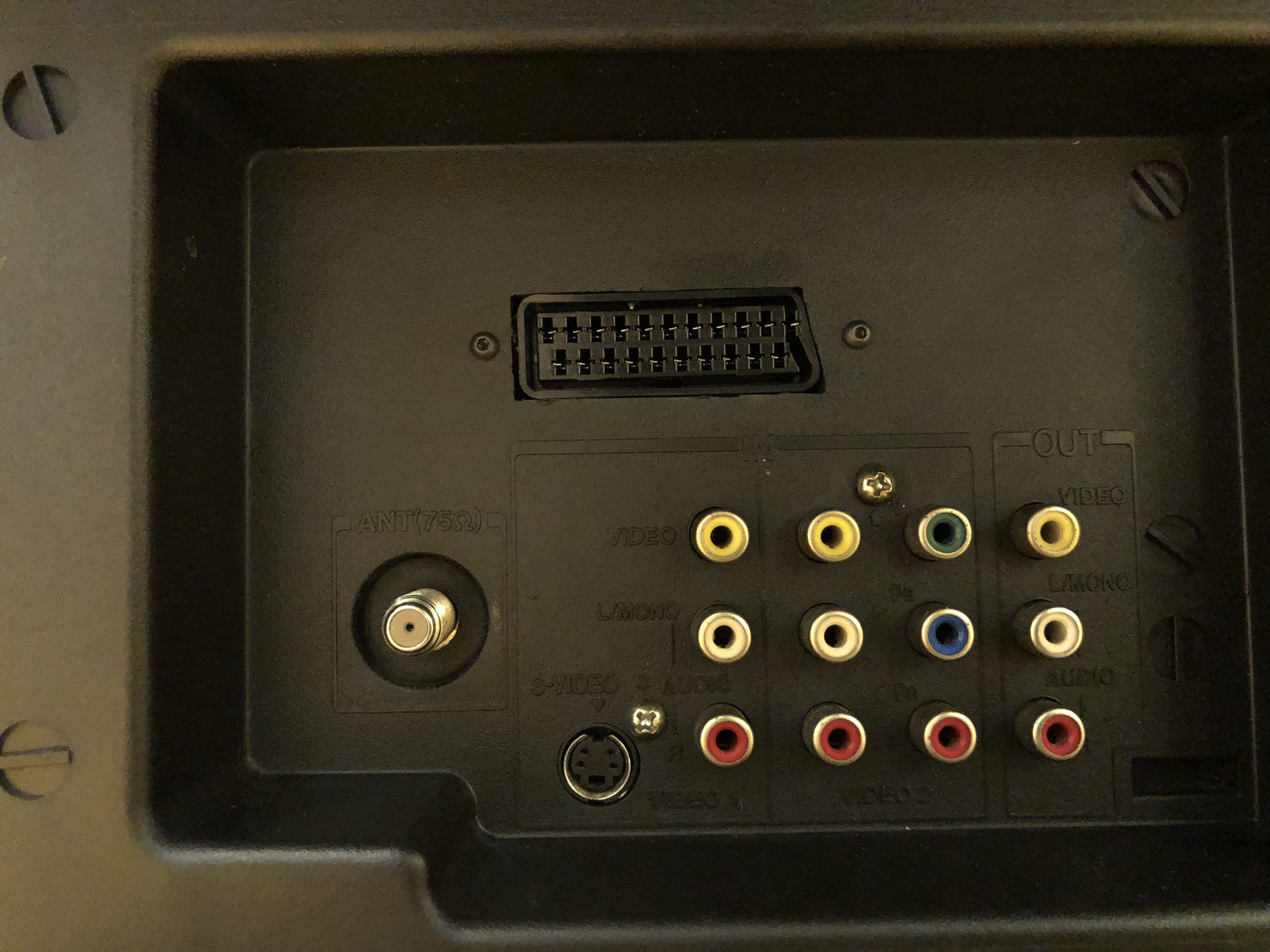
STEP 5: Attach the female SCART connector to TV
Creating a SCART cutout and mounting it is an art. I have a dedicated section for it. How to create and mount a SCART female plug?
Pictures
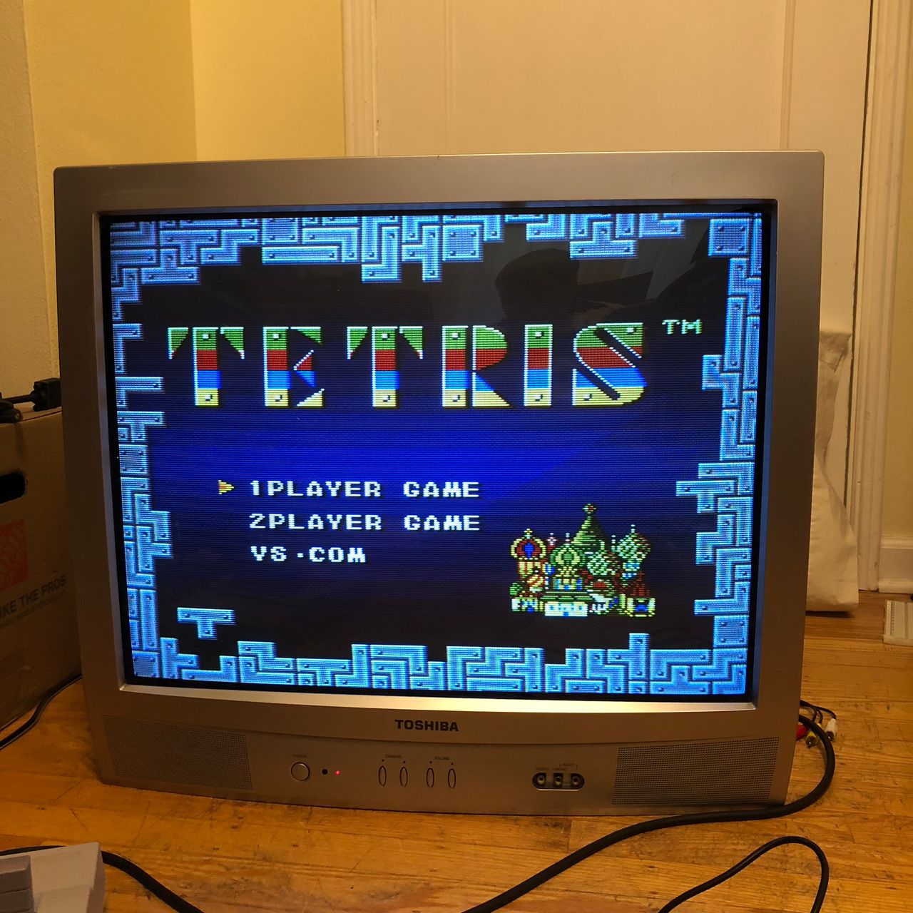
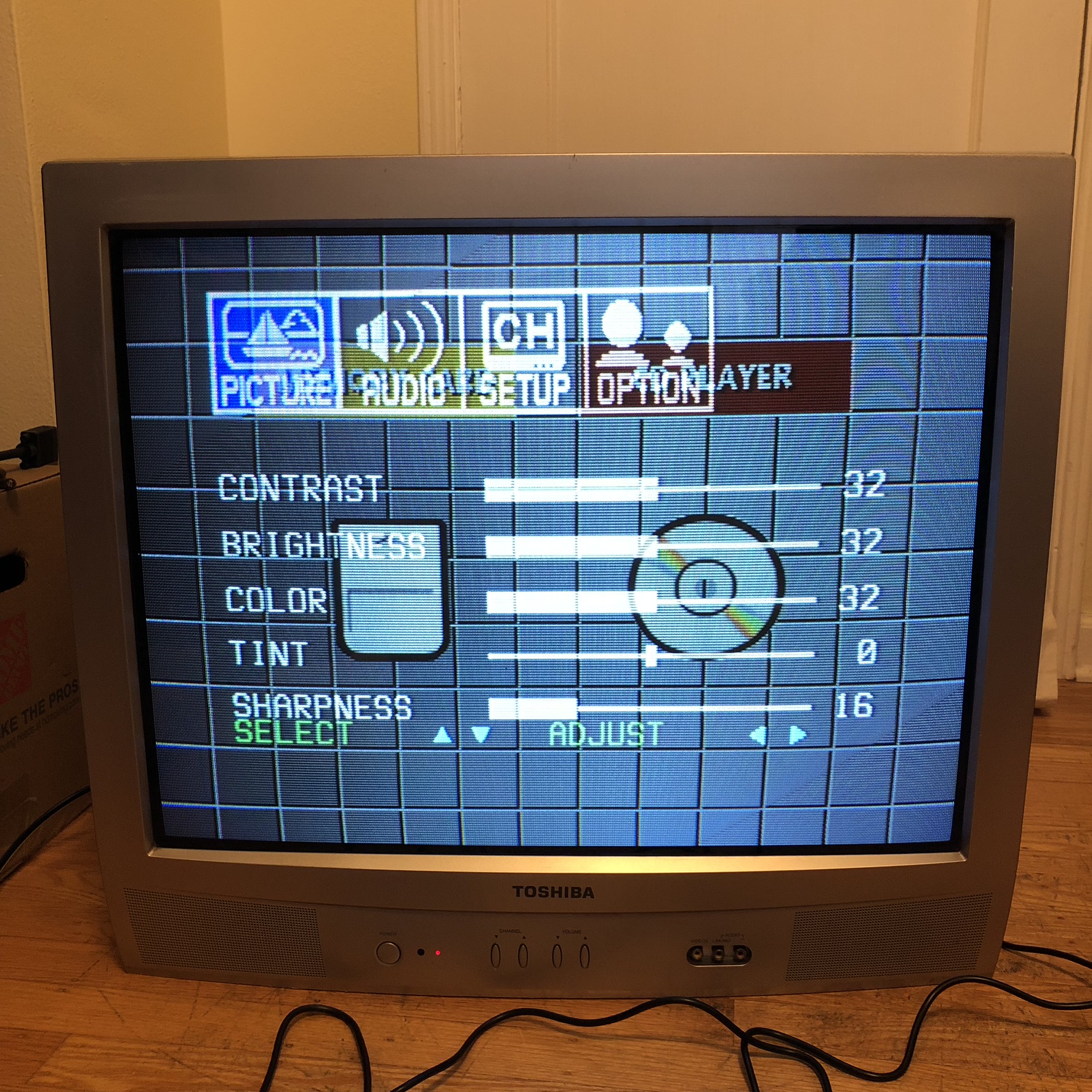
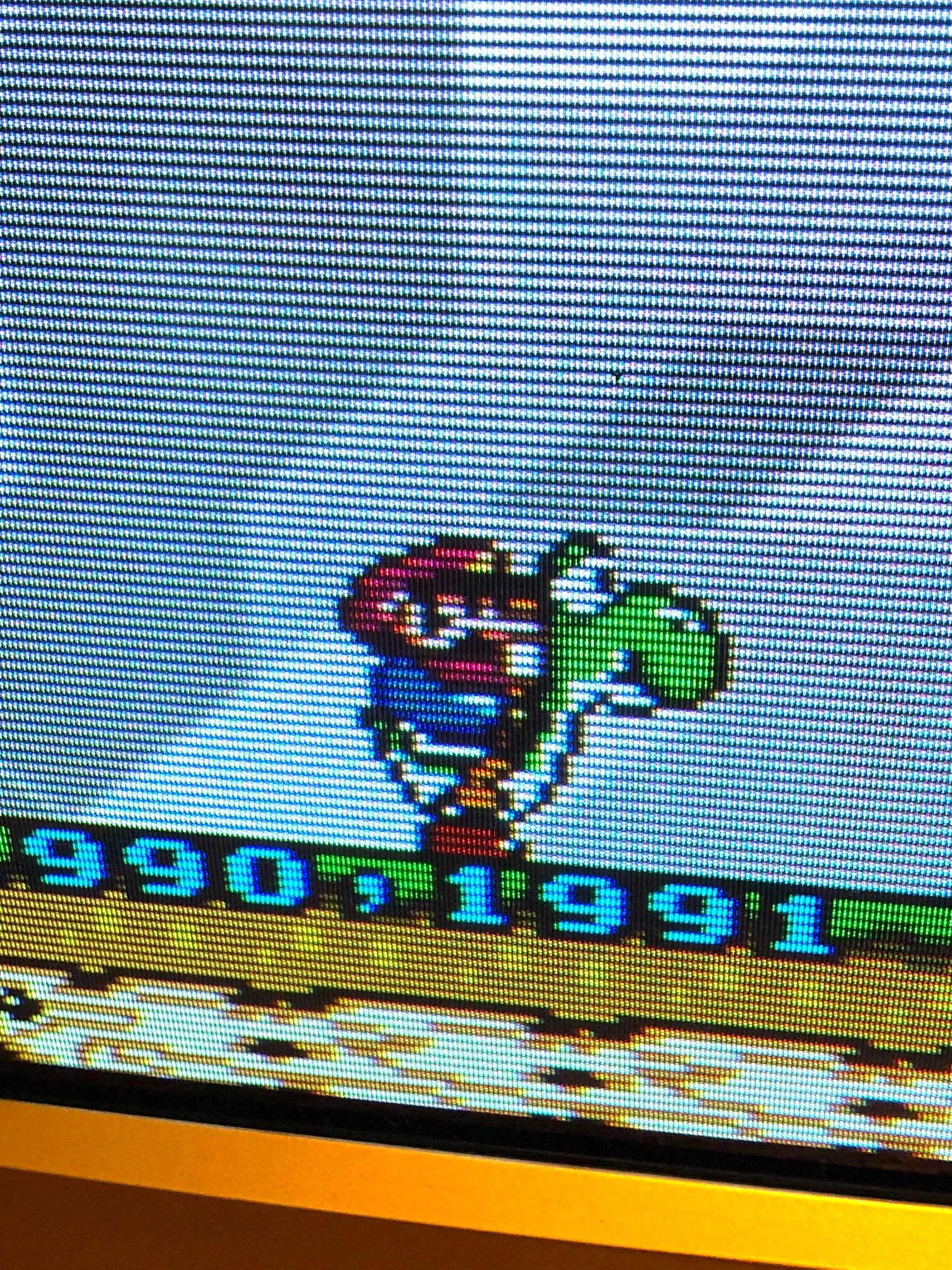
Muxed OSD over RGB
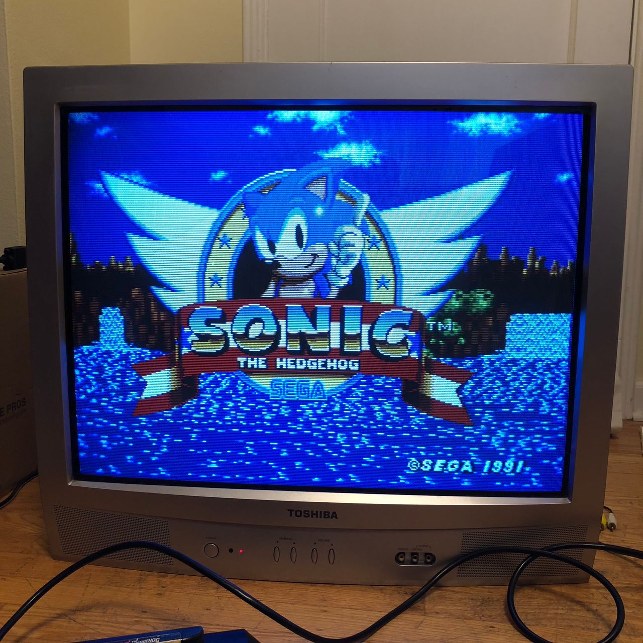
Games
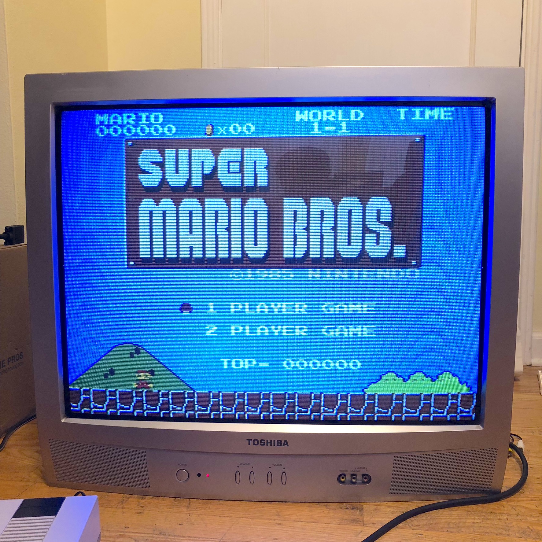
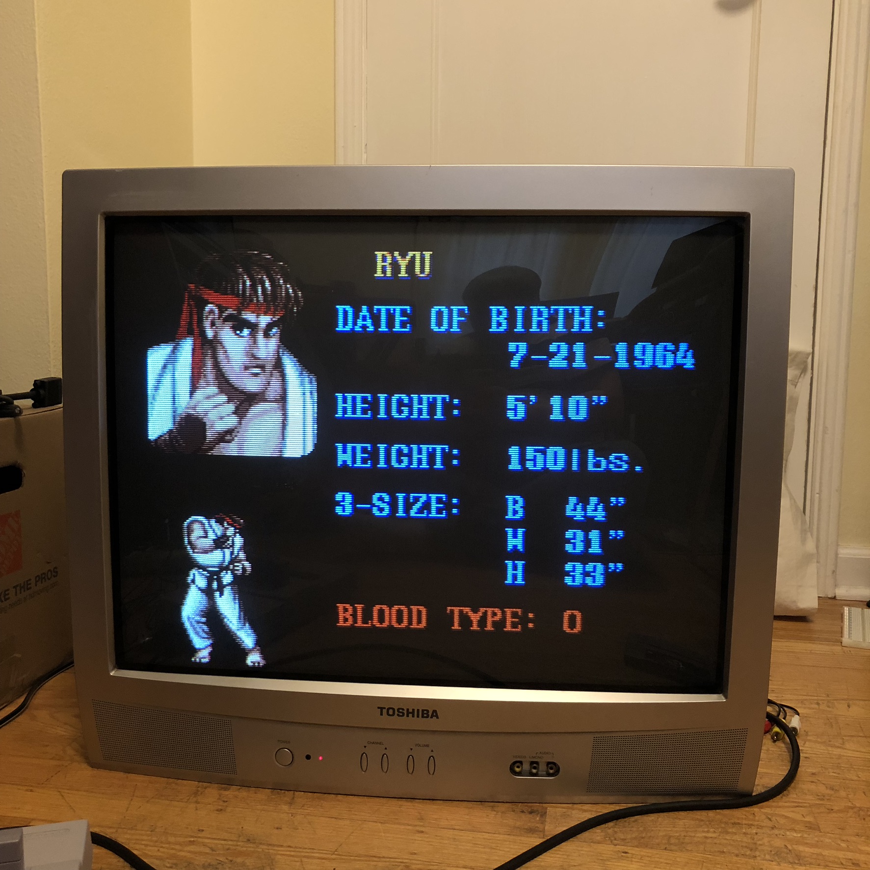
Pictures
Reference Photos