Toshiba 13A21
Toshiba 13A21 CRT RGB mod
The Toshiba 13A21 is a compact 13" CRT display. One of the standout characteristics of the 13A21 is its modifiability; it can be upgraded with RGB input via the mux method.
Overall, the Toshiba 13A21 combines a classic design with modern adaptability, making it an excellent addition to any retro gaming or vintage display collection.

View full CRT details and more mod examples →
This mod should also work for the below models
- Toshiba 13A21
- Toshiba 19A21
This mod doesn't work for the below models. Below models use a single-chip. In the absence of OSD chip, RGB mod is not possible.
- Toshiba 13A23
- Toshiba 13A24
- Toshiba 13A25
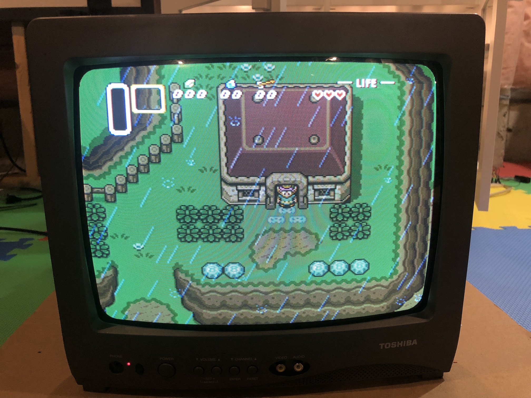
Table of Contents
Contributors
Thank you to everyone who contributed to this guide:
- Sunthar — contributor, RGB mod and pictures
CRT safety
Caution
You can die doing this! So read carefully! CRT TV is not a toy. Do not open a CRT TV. If you don't have any prior knowledge about handling high voltage devices, this guide is not for you. CRT TV contains high enough voltage (20,000+ V) and current to be deadly, even when it is turned off.
Plan of attack
Manuals and Datasheets
Specs
- Manufactured: Thailand (2001)
- Chassis: M3J88
- Tube: Orion A34AGT13X98
- Jungle Chip: Renesas M61206FP
- OSD Chip: Orion OEC7063A
- Screen Size: 13"
- Power: 54 W
- Weight: 20.9 lbs
- Inputs: RF, Composite
Schematics
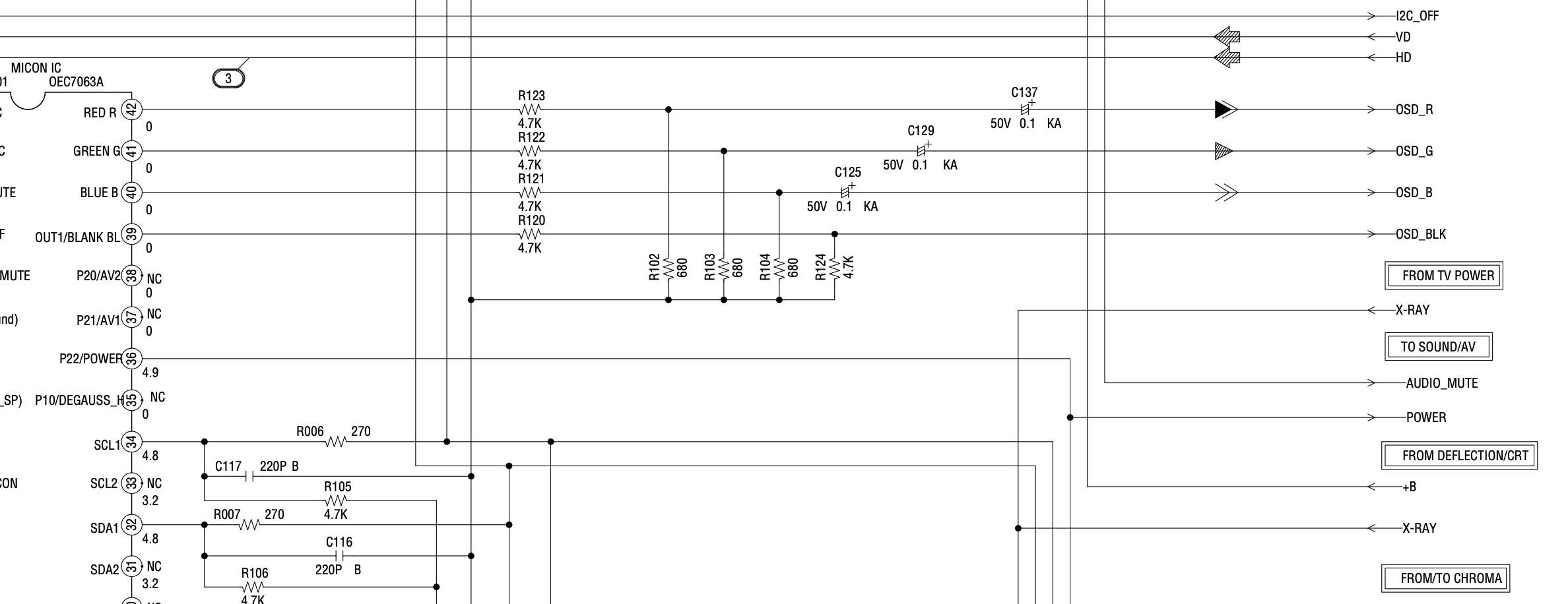
Get hold of the schematics for your TV. Understand where the RGB and Fast Blanking signals go from OSD to the Jungle (Chroma) chip.
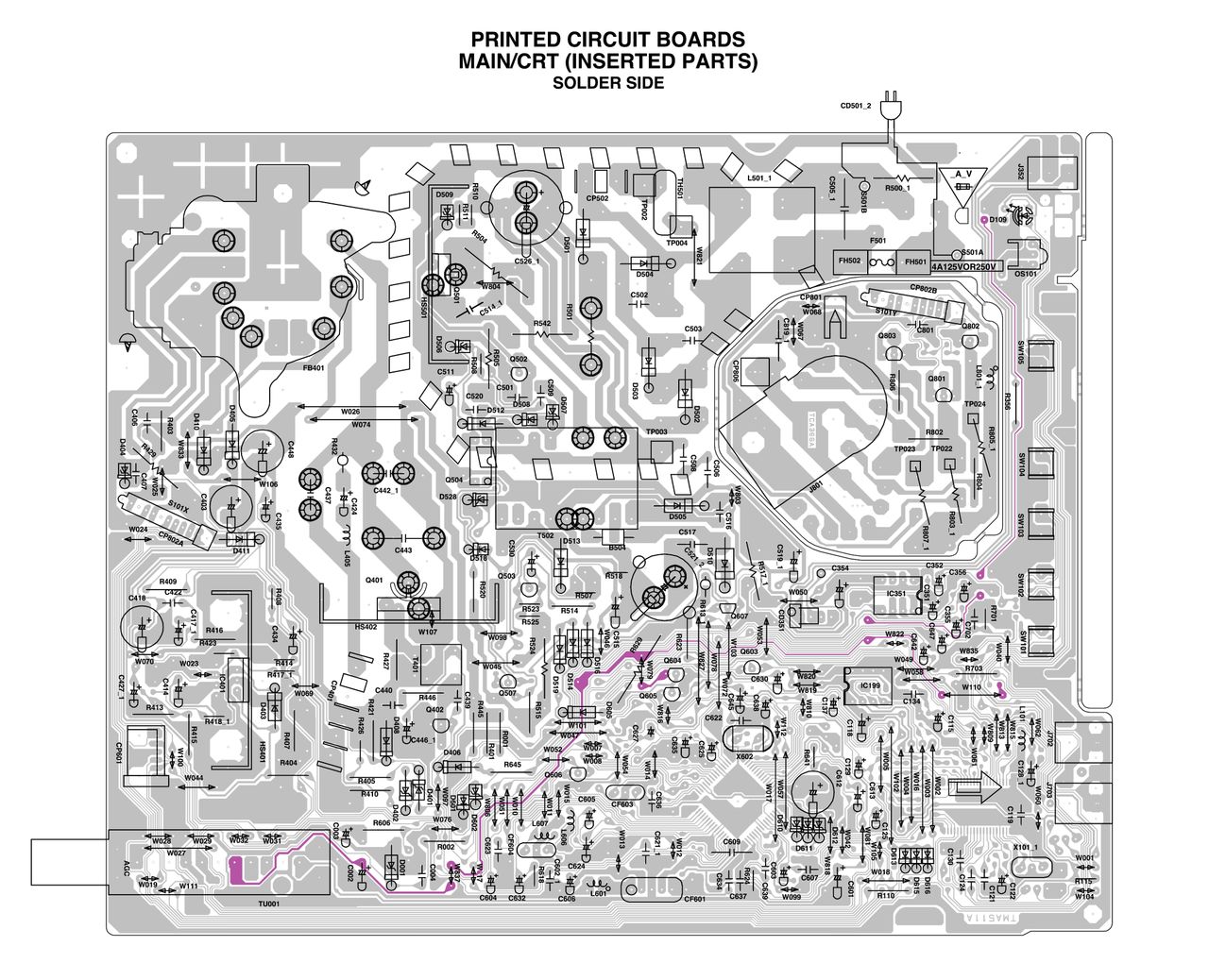
PCB
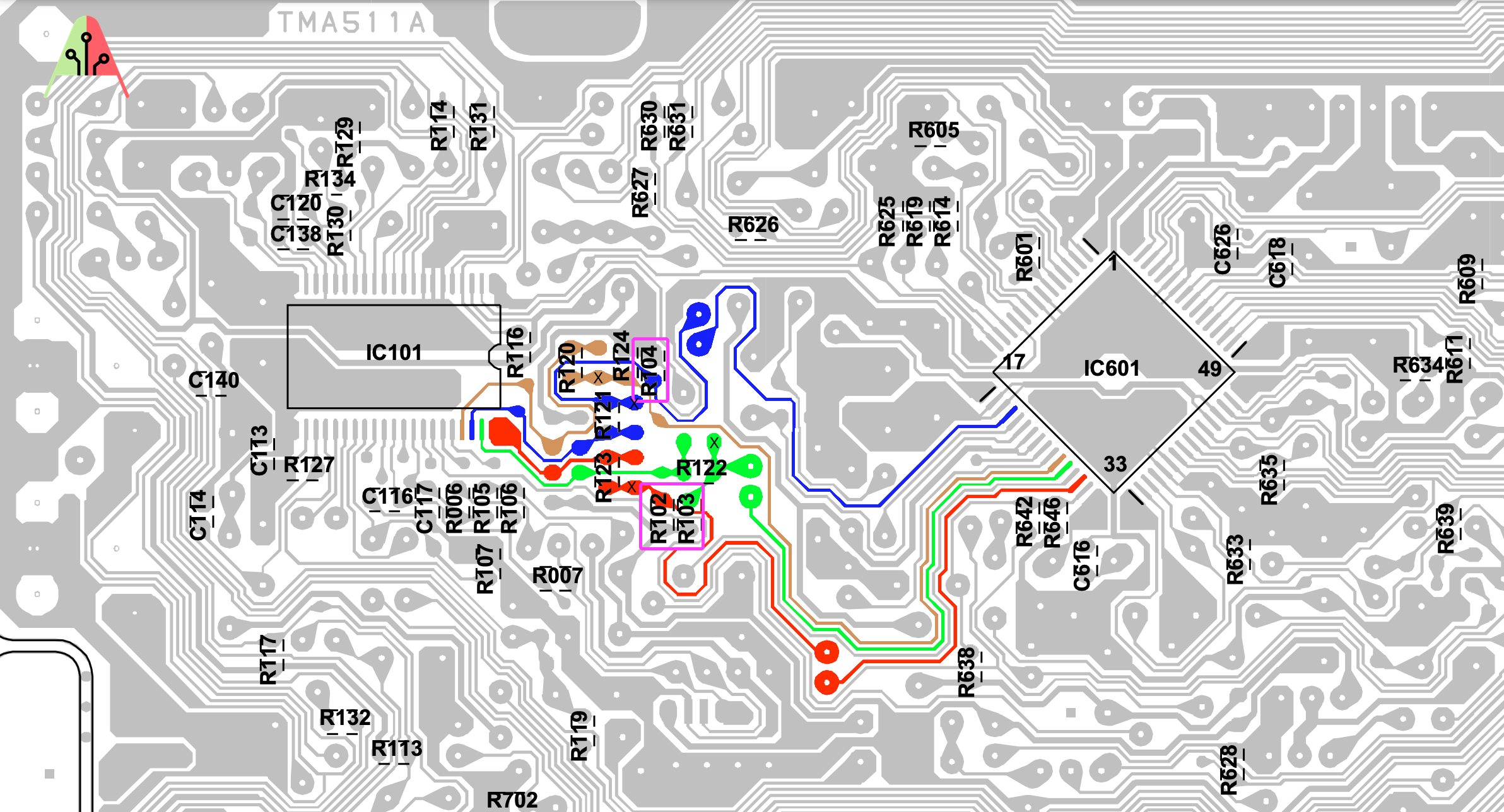
Points where the R, G, B and Blanking (brown) wires should be connected are marked "X". Pink boxes show the resistors that needs to be removed.
RGB mux diagram
Prepare the mux diagram. If you are building your own circuit, this diagram should help.
Performing the mod
STEP 1: Remove the following components
Remove the three 680 ohm, RGB resistors to ground
- R102
- R103
- R104
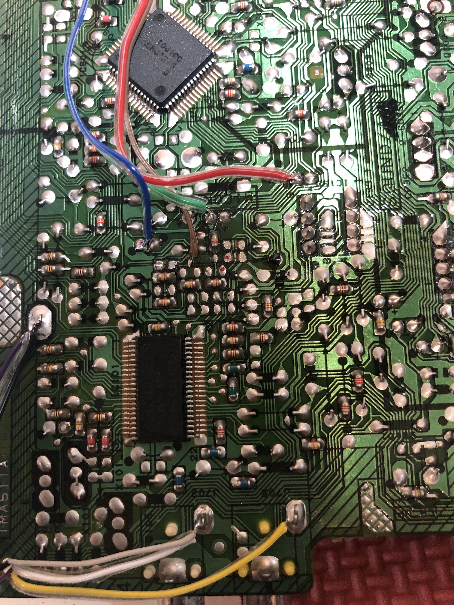
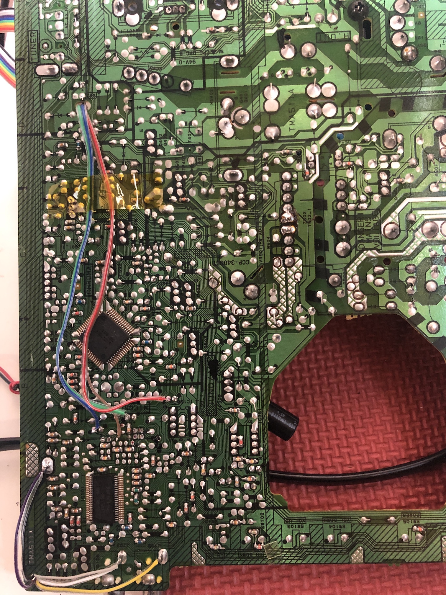
STEP 2: Connect RGBs, Blanking and Audio
STEP 3: Build your mux circuit
This mod uses the RGB mux board. This is optional, but will make your mod easier and stable. You can also create the circuit presented in the schematics above without the board. Please also checkout the mux calculator to play with your own values.
| On Toshiba CRT Chassis | 13A21 |
|---|---|
| CRT RGB inline resistor | 4.7kΩ |
| CRT RGB ground resistors removed | 680Ω |
| 0.1μF caps replaced | No |
| Add diodes on chassis RGB lines? | No |
| Add blanking diode on chassis | No |
| RGB mux board | 13A21 |
|---|---|
| Mux board RGB termination (R1, R2, R3) | 75Ω |
| Mux board RGB inline resistors (R4, R5, R6) | 680Ω |
| Mux board Audio LR (R7, R8) | 1kΩ |
| Mux board blanking diode (R9) | 1N4148 |
| Mux board blanking ground resistor (R10) | open |
| Mux board blanking resistor (R11) | 4.7kΩ |
Compatible mux boards:
Back 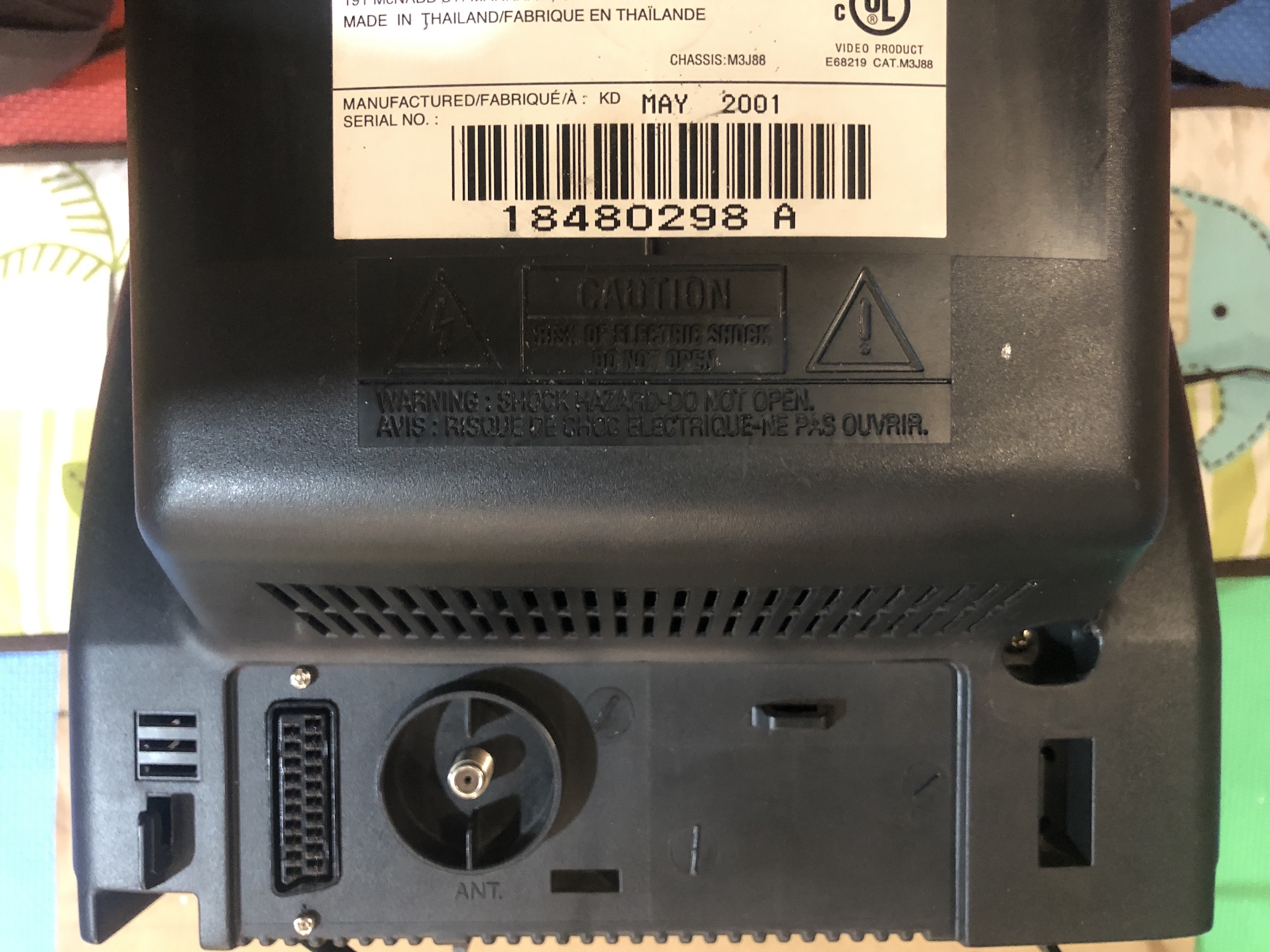
SCART connector 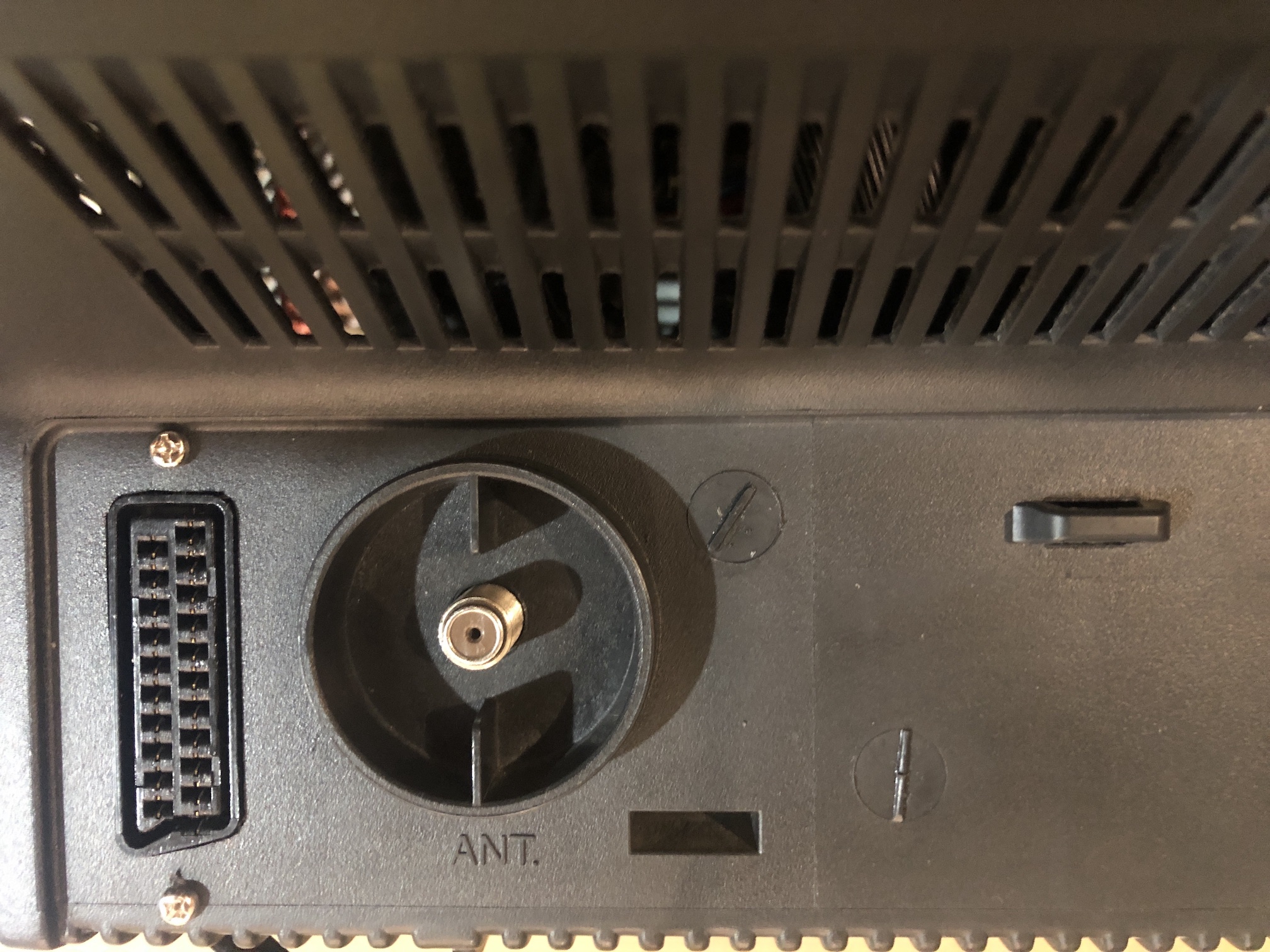
STEP 4: Attach the female SCART connector to TV
Creating a SCART cutout and mounting it is an art. I have a dedicated section for it.
SCART connector mounted 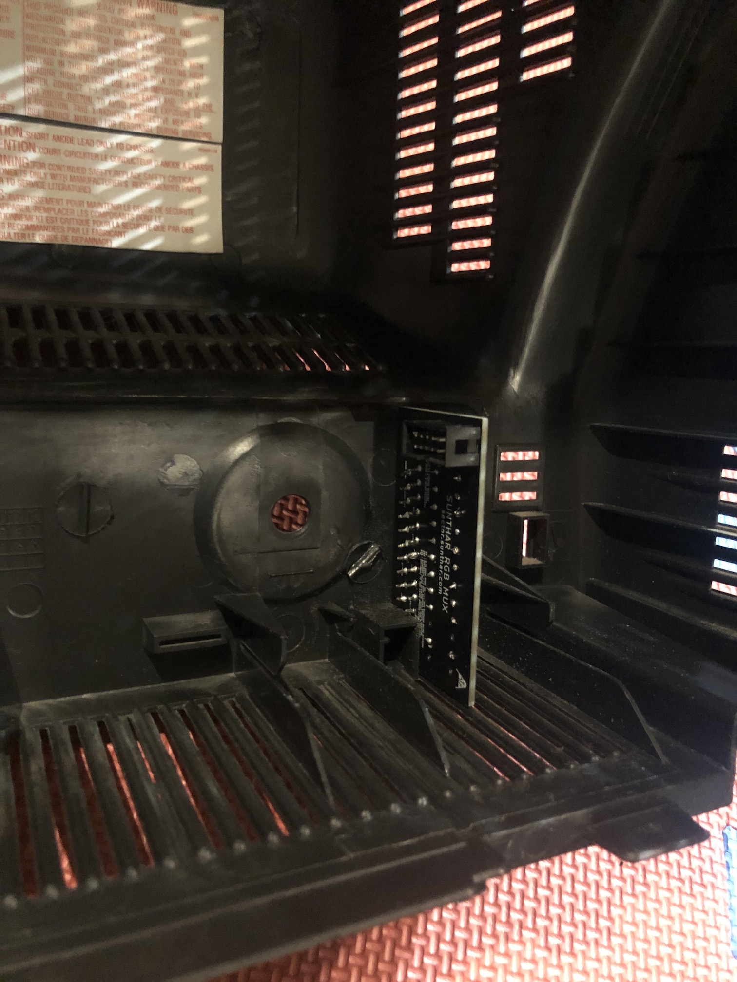
How to create and mount a SCART female plug?
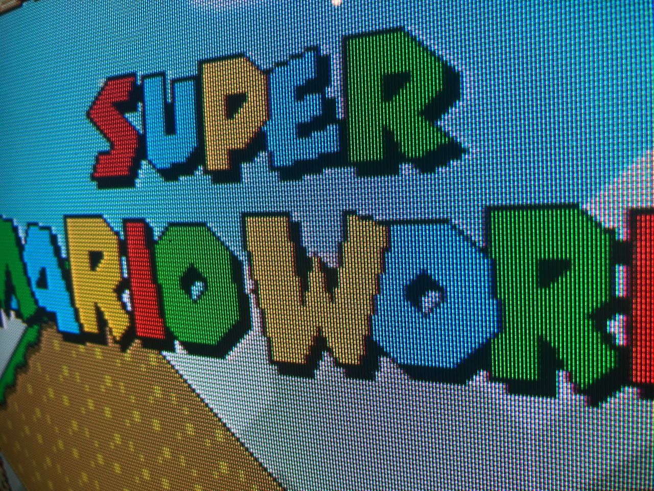
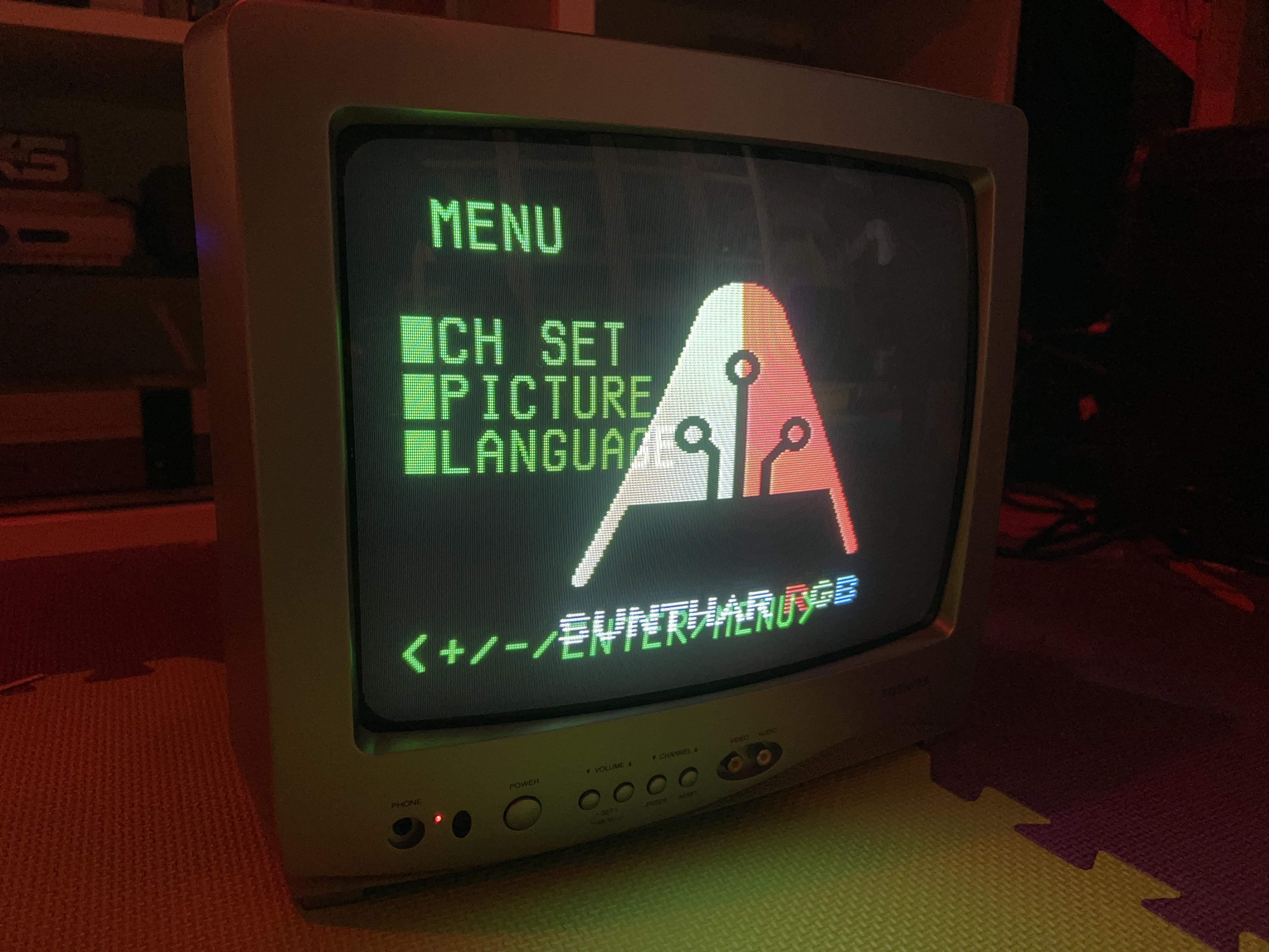
OSD overlay
Games
SNES - The Legend of Zelda A Link to the Past
SNES - Super Mario World 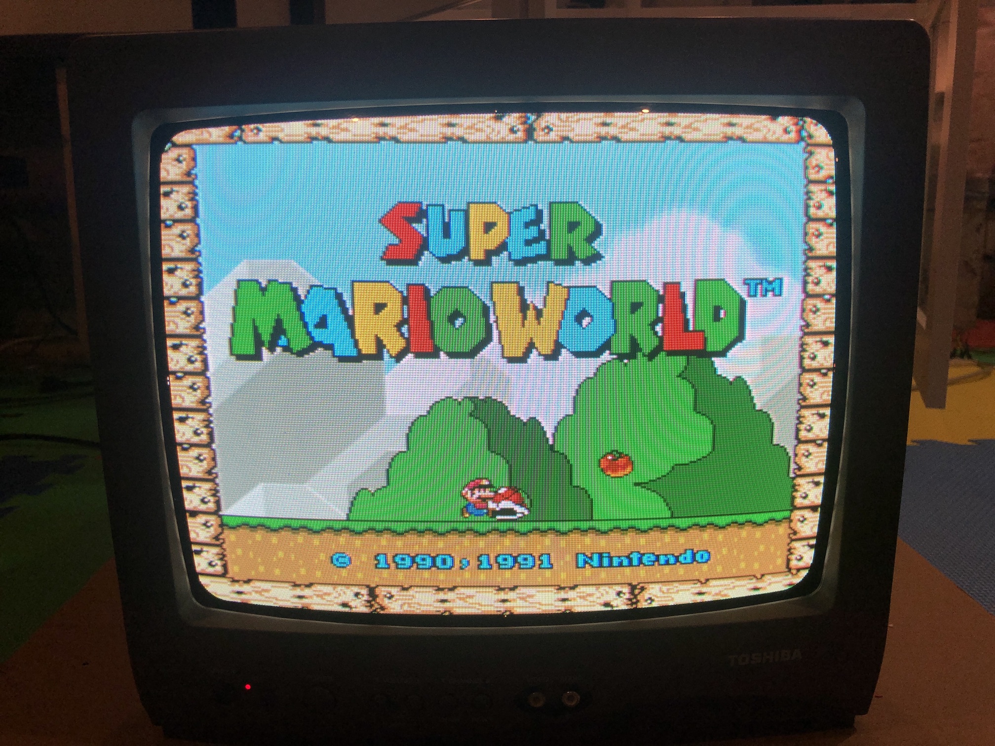
SEGA Genesis - Sonic 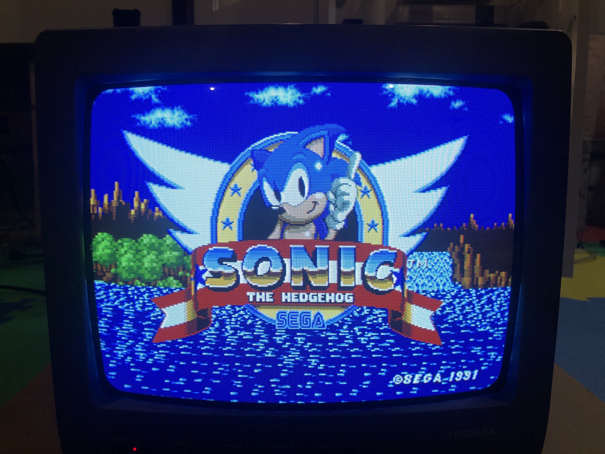
NES - 1942 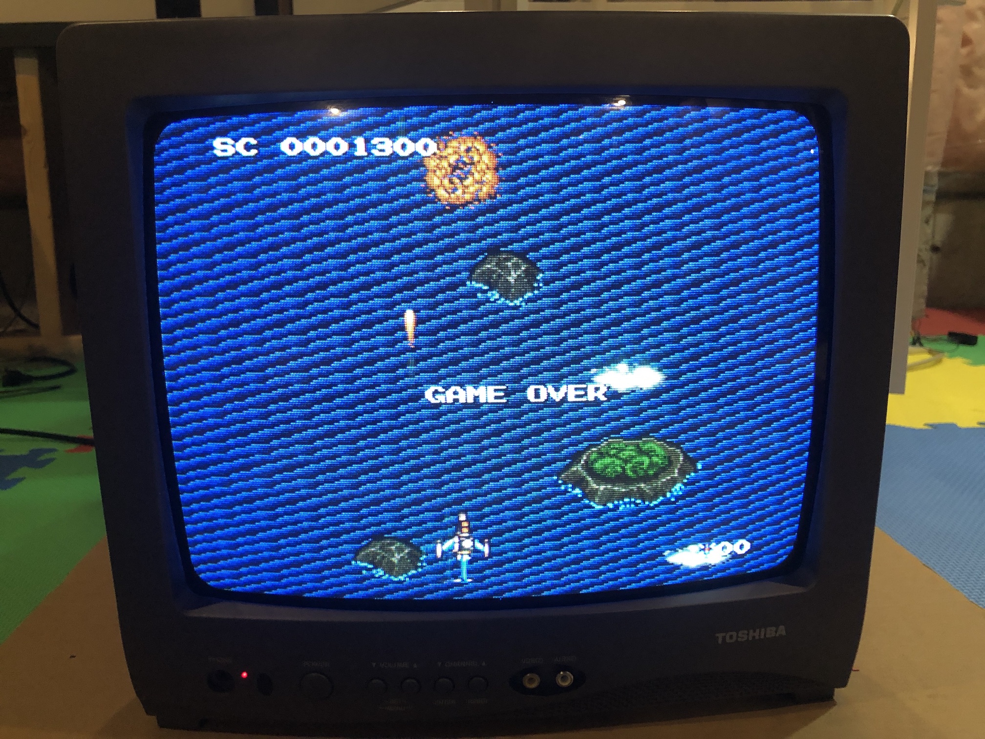
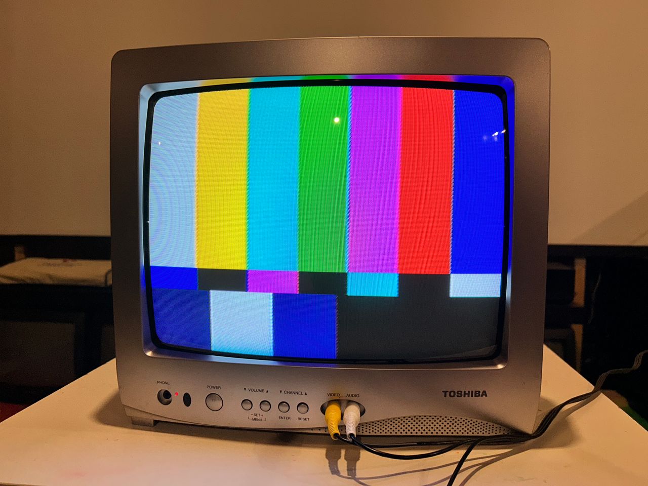
Patterns
240p - Grid 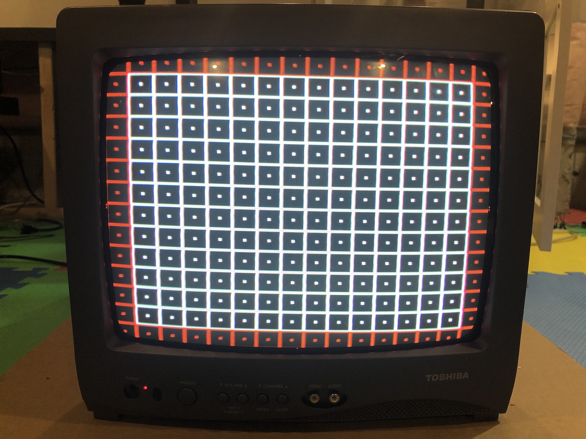
Random Pics
Back cover open 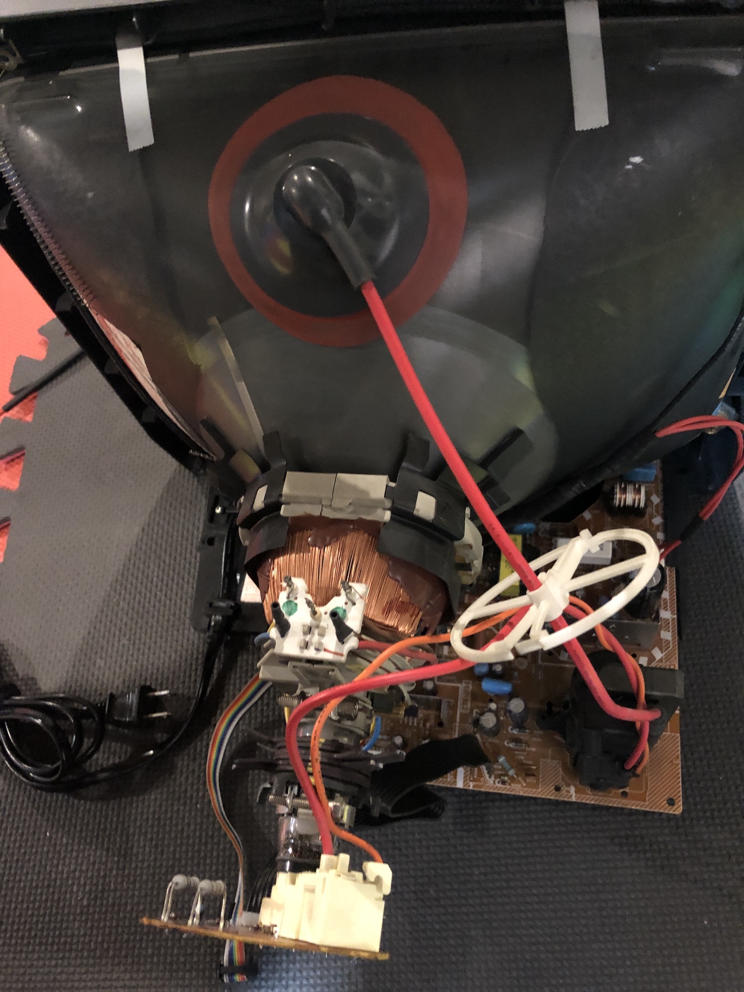
Pictures
Reference Photos