Sharp 27F-S50
Sharp 27F-S50 (SN-41) CRT RGB mod (work in progress)
This tutorial covers the RGB mod for Sharp 27F-S50. These instructions should also work for the below CRTs.
- Sanyo 27F-S50
- Sanyo 27F-S40
- Sanyo 27F-S100
- Sanyo 27F-S120
CRT safety
Caution
You can die doing this! So read carefully! CRT TV is not a toy. Do not open a CRT TV. If you don't have any prior knowledge about handling high voltage devices, this guide is not for you. CRT TV contains high enough voltage (20,000+ V) and current to be deadly, even when it is turned off.
Plan of attack
Theory
Sometimes it is nice to know the theory behind the mod. I have put this on a separate page. This shows how the various resistor values are calculated.
Specs
Sharp 27F-S50
- Manufactured: Made in USA, March 1995
- NTSC 125W 60 Hz
- Chassis: SN-41
- Chroma: IX2429CE (IC201)
- OSD: IX2428CE (IC2001)
Service manuals
Schematics

Calculating the RGB external resistor value (R4, R5, R6)
Love it when we can put theories to use! Formula from our theory page!
We find out using ohms law, this CRT is using 1Vp-p to 1.2Vp-p.

RGB external resistor value
= (1 x (5600 + 220) - (220 x (5-0.7))) / (5 - 0.7)
= (5820 - 946) / 4.3
= 4874 / 4.3
= ~1 kΩ
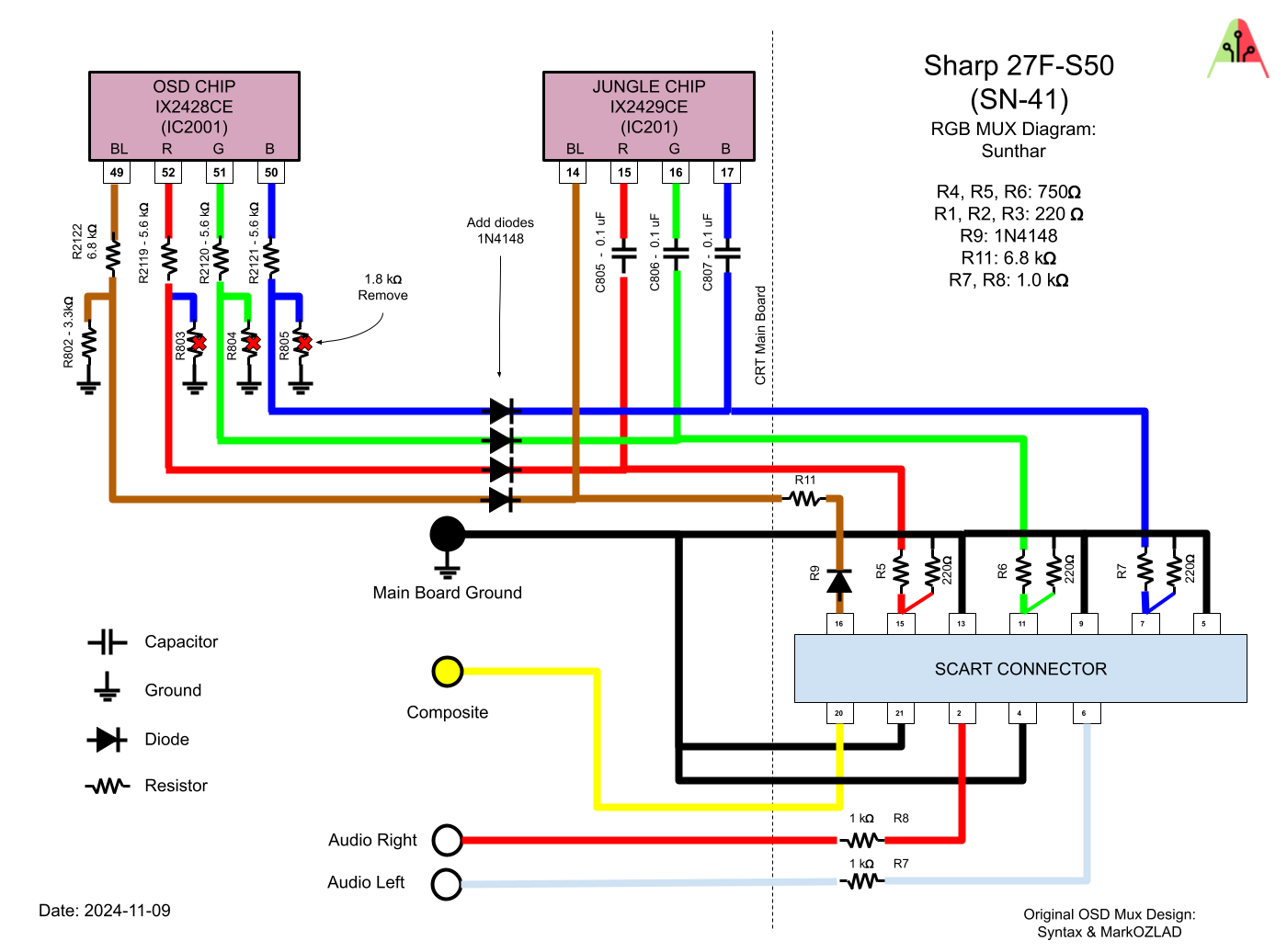
We can try 750ohms for (R4, R5 and R6) with diodes inline. If the RGB image looks dim or if the OSD is not clearly visible, then we can move to 1kohm resistors.
Performing the mod
Now that you roughly know what needs to be done, prepare for the mod. Place the board on a comfortable place. Make sure you are not putting pressure on the flyback or other components.
STEP 1: Remove the following components
Remove the following components. RGB resistors to the ground. Measure twice and mark before you remove.
- R803 (1.8 kΩ)
- R804 (1.8 kΩ)
- R805 (1.8 kΩ)
STEP 2: Connect RGB, Blanking
STEP 3: Blanking diode
To prevent current from flowing back into the OSD and causing interferences in RGB mods, it's necessary to include a diode in the blanking line. The absence of this diode is the main cause of such issues.
STEP 4: Sync and Audio
STEP 5: Build your mux board
Below mod uses the RGB mux board. This is optional, but will make your mod easier and stable. You can also create the circuit presented in the schematics above without the board. Please also checkout the precalculated resistor values.
| On Sanyo CRT Chassis | Sharp 27F-S50 |
|---|---|
| CRT RGB inline resistor | 5.6kΩ |
| CRT RGB ground resistors removed | 1.8kΩ |
| CRT RGB inline cap value | 0.1uF |
| Add blanking diode on chassis? | Yes |
| RGB mux board | Sharp 27F-S50 |
|---|---|
| Use RGB inline diodes on CRT chassis? | Yes? |
| Mux board Audio LR (R7, R8) | 1kΩ |
| Mux board RGB termination (R1, R2, R3) | 220Ω |
| Mux board RGB inline resistors (R4, R5, R6) | 750Ω |
| Mux board blanking diode (R9) | 1N4148 |
| Mux board blanking ground resistor (R10) | 6.8kΩ |
