Sansui TVM1316B
Sansui TVM1316B CRT RGB mod
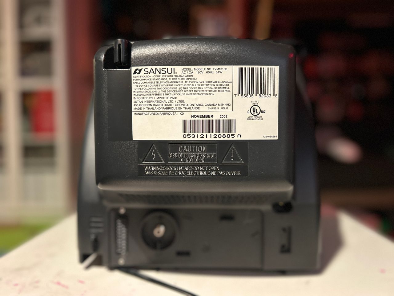
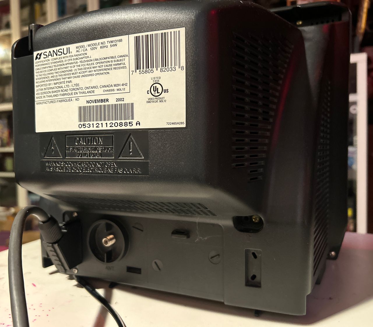
Sansui TVM1316B, is a classic 13-inch consumer grade CRT.
One of the standout features of the TVM1316B is its modifiability; it supports RGB input via the 1.3B RGB MUX Kit, allowing users to enhance their visual experience. RGB modification is similar to Toshiba 13A22.
View full CRT details and more mod examples →
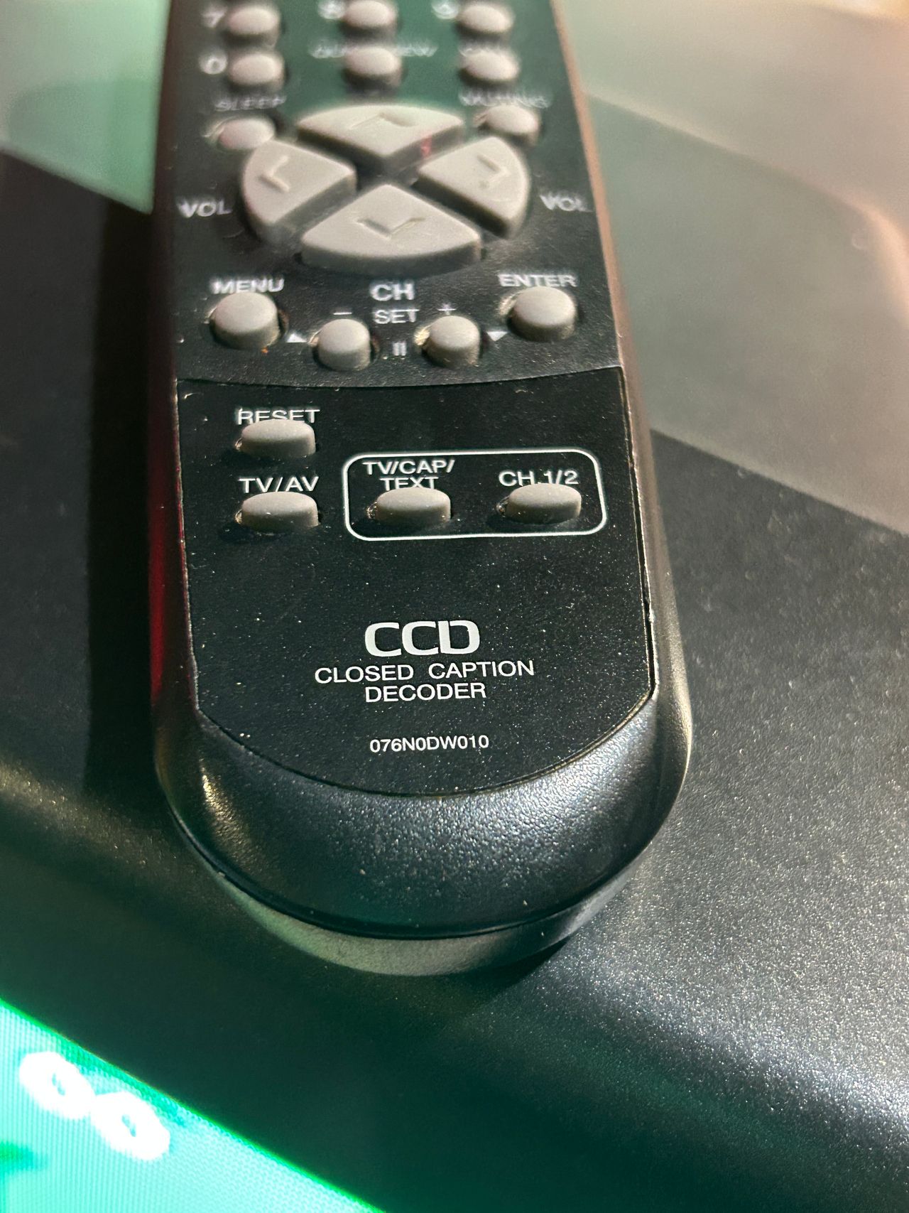
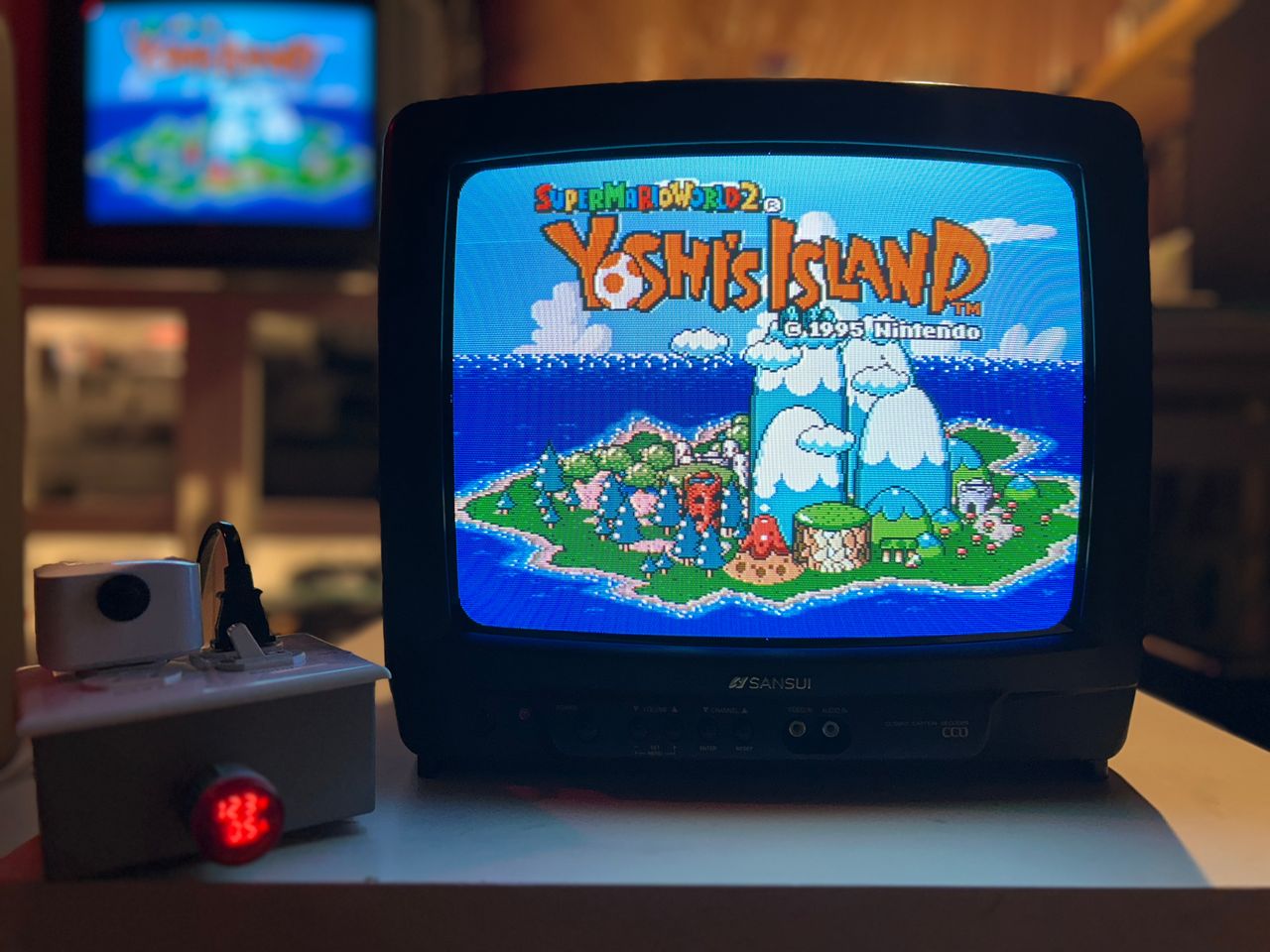
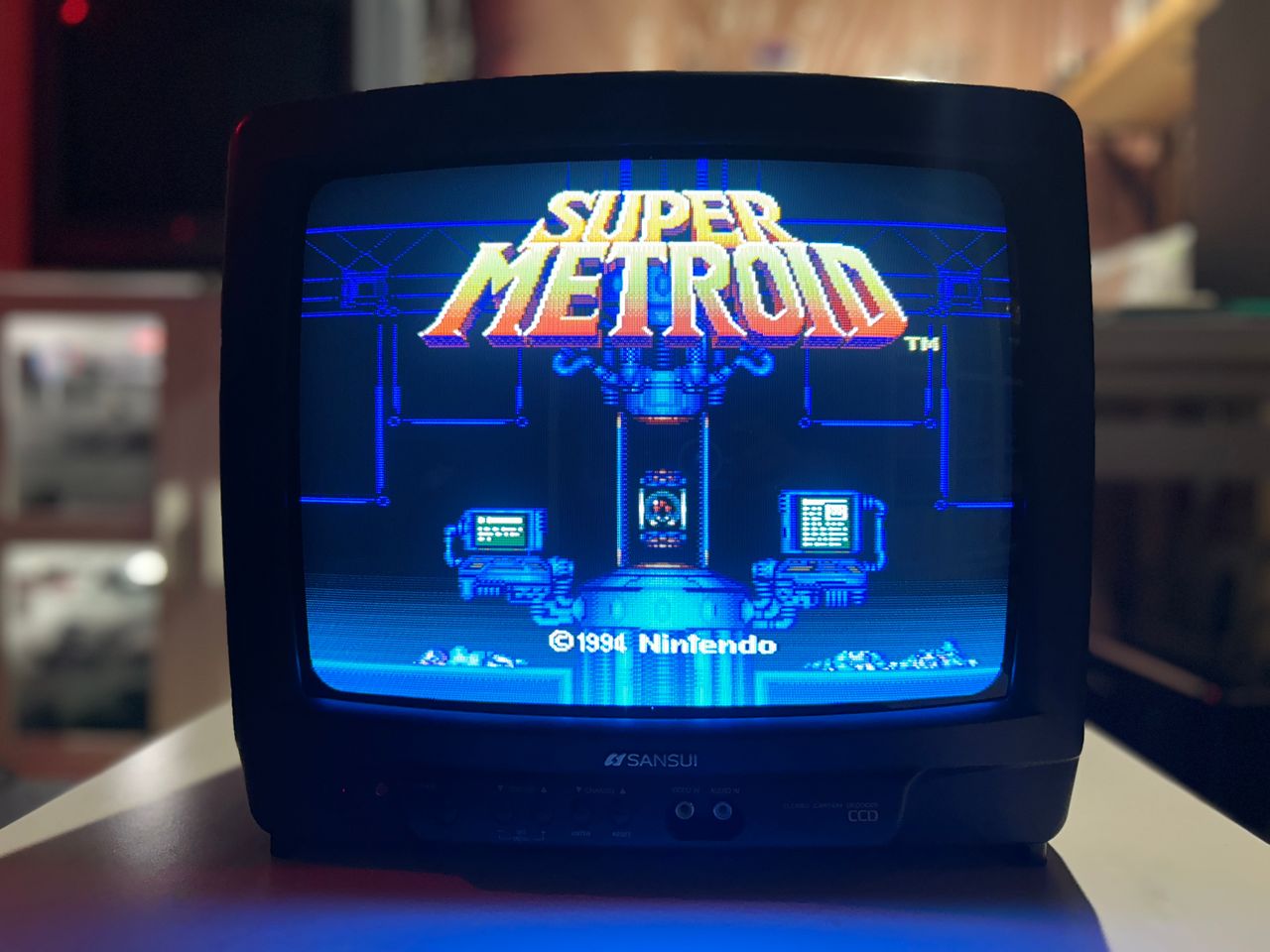
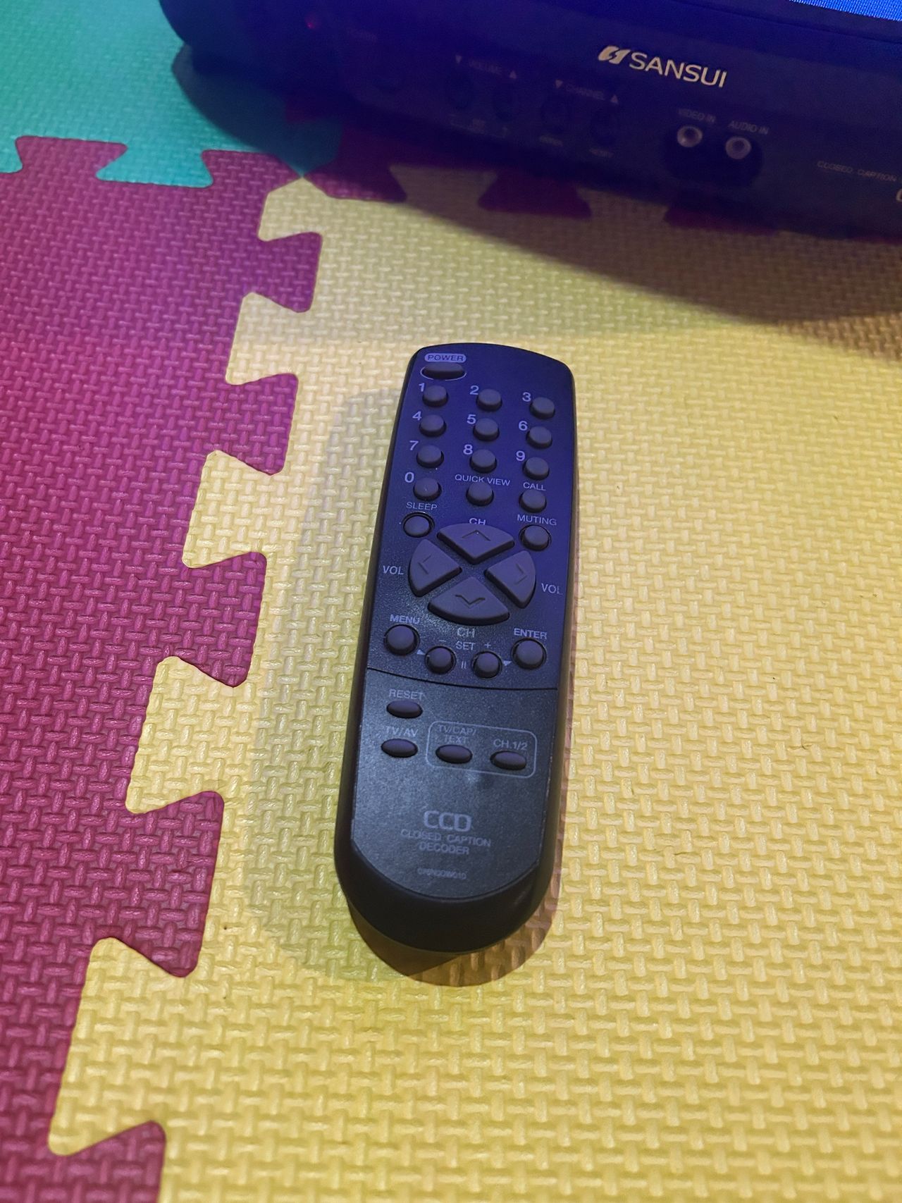
This RGB mod turned out well. The tube is plenty bright, and direct RGB input made a noticeable improvement over stock composite video. For how the IR receiver was fixed (and the compatible remote that got the set working again), see the Pictures section below.
Please note that not all versions of Sansui, Toshiba, Panasonic's are RGB moddable, even though they might look alike from outside. Later models use a single-chip. And in the absence of OSD chip, RGB mod is not easily possible. These sets exhibit a slight ringing interference in certain scenes. However, it is hardly noticeable.
This mod should also work for the below models
- Toshiba 13A22
- Panasonic CT-13R37S
Contributors
Thank you to everyone who contributed to this guide:
- Sunthar — author, contributor, RGB mod and pictures
CRT safety
Caution
You can die doing this! So read carefully! CRT TV is not a toy. Do not open a CRT TV. If you don't have any prior knowledge about handling high voltage devices, this guide is not for you. CRT TV contains high enough voltage (20,000+ V) and current to be deadly, even when it is turned off.
Plan of attack
Manuals and Datasheets
Specs
- Manufactured: Thailand (2002)
- Chassis: M3L12
- Tube: Orion A34AGT13X98
- Jungle Chip: Renesas M61250FP
- OSD Chip: Orion OEC7063A
- Screen Size: 13"
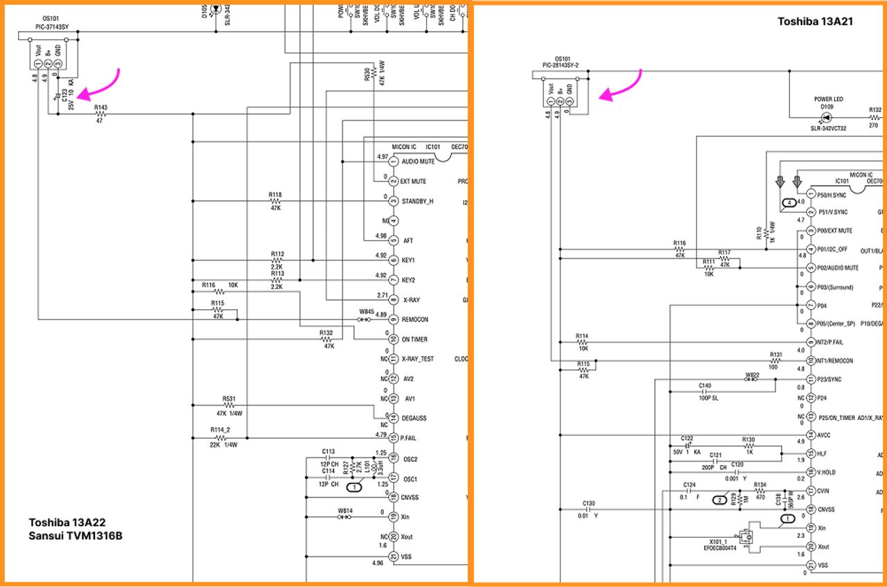
RGB mux diagram
Prepare the mux diagram. If you are building your own circuit, this diagram should help.
Performing the mod
STEP 1: Remove the following components
Remove the three 680 ohm, RGB resistors to ground
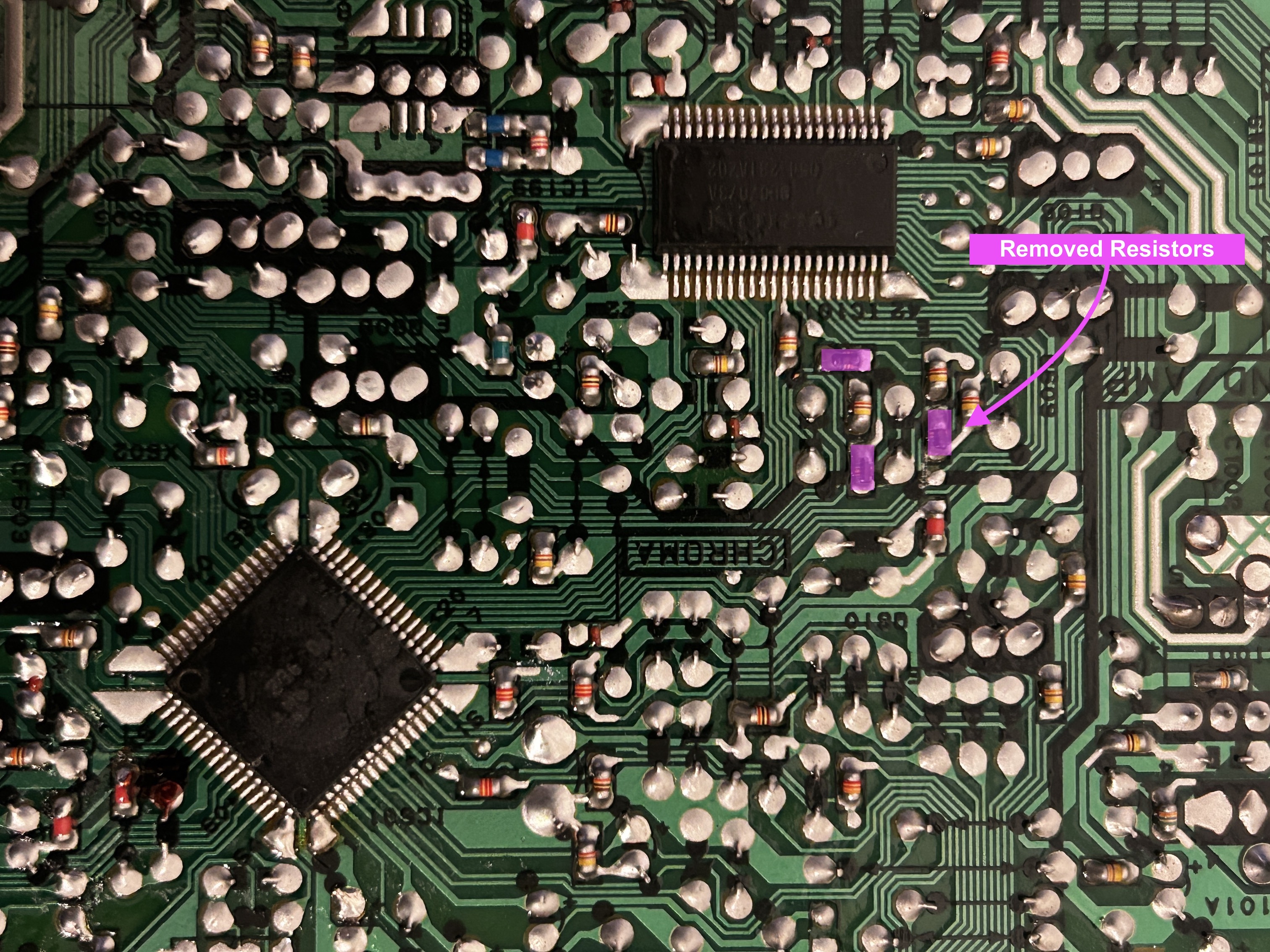
- R102
- R103
- R104
STEP 2: Connect RGBs, Blanking and Audio
Sync and ground wires 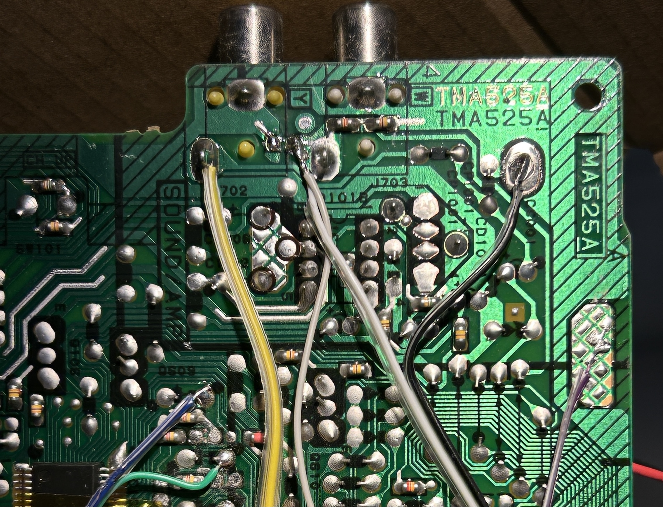
Blanking and RGB wires ![]()
Overall mod 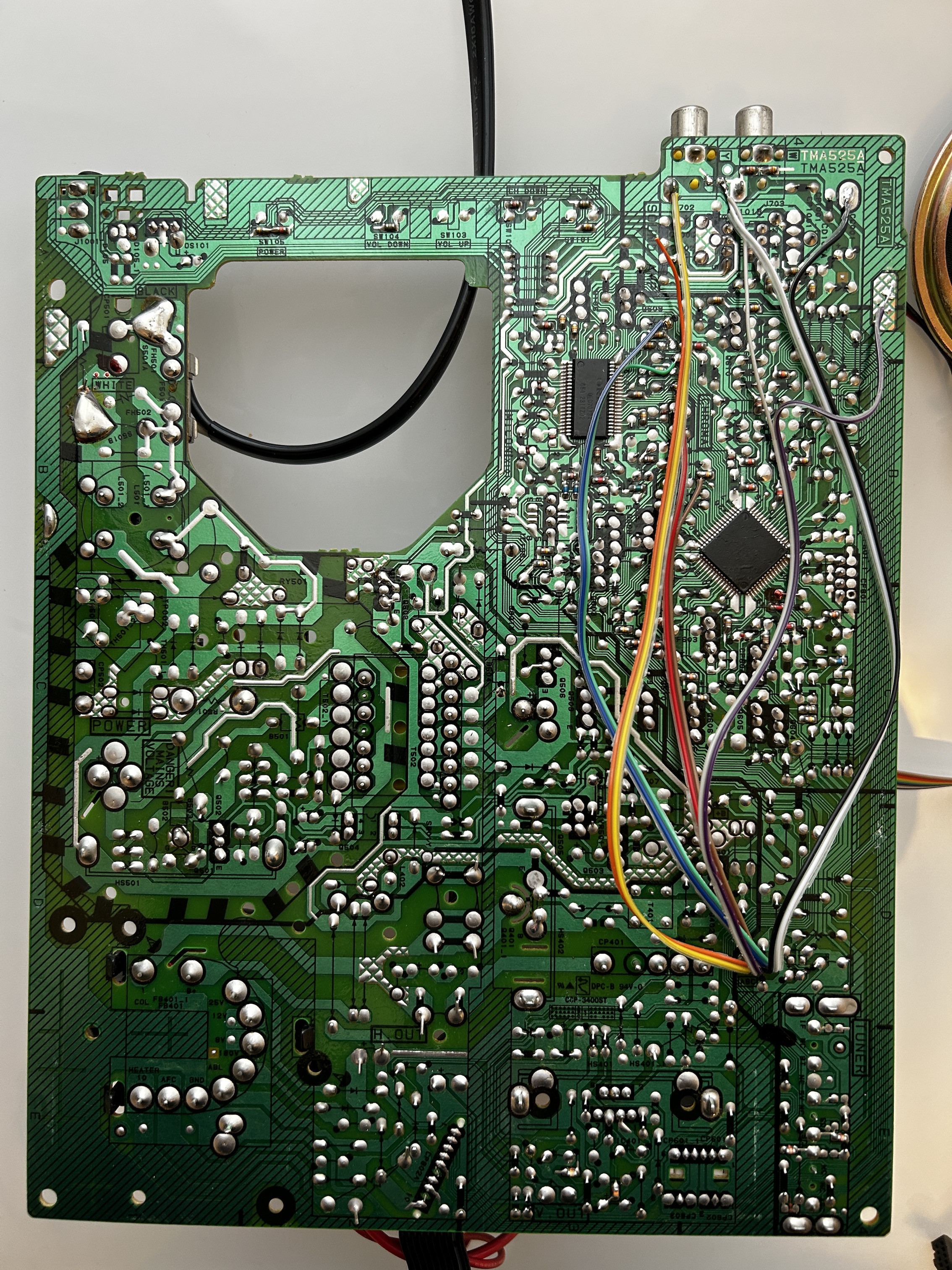
STEP 3: Build your mux circuit
This mod uses the RGB mux board. This is optional, but will make your mod easier and stable. You can also create the circuit presented in the schematics above without the board. Please also checkout the mux calculator to play with your own values.
| On Sansui CRT Chassis | TVM1316B |
|---|---|
| CRT RGB inline resistor | 4.7kΩ |
| CRT RGB ground resistors removed | 680Ω |
| RGB mux board | TVM1316B |
|---|---|
| Mux board RGB termination (R1, R2, R3) | 75Ω |
| Mux board RGB inline resistors (R4, R5, R6) | 680Ω |
| Mux board Audio LR (R7, R8) | 1kΩ |
| Mux board blanking diode (R9) | 1N4148 |
| Mux board blanking ground resistor (R10) | open |
| Mux board blanking resistor (R11) | 4.7kΩ |
Compatible mux boards:
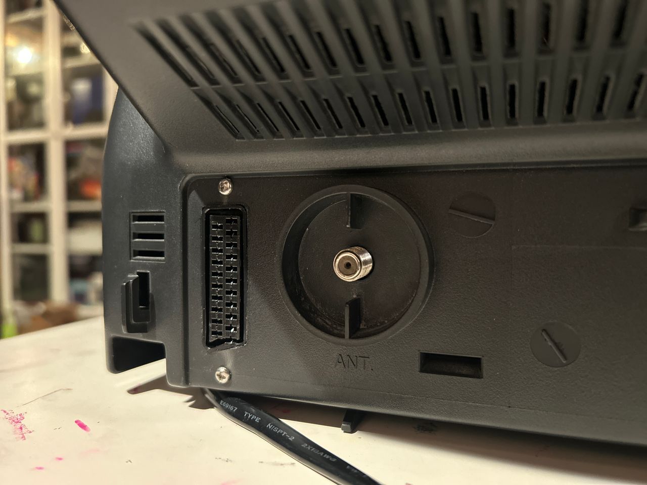
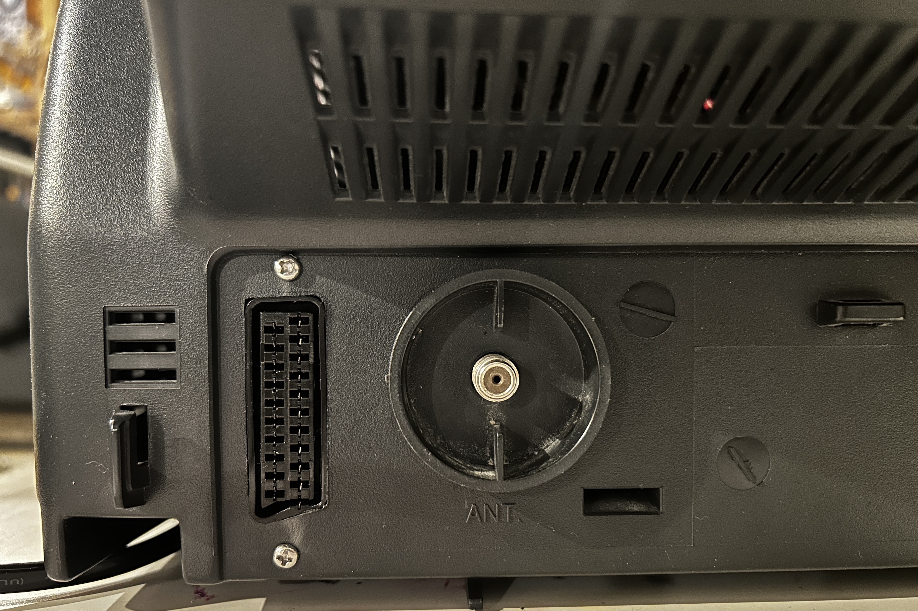
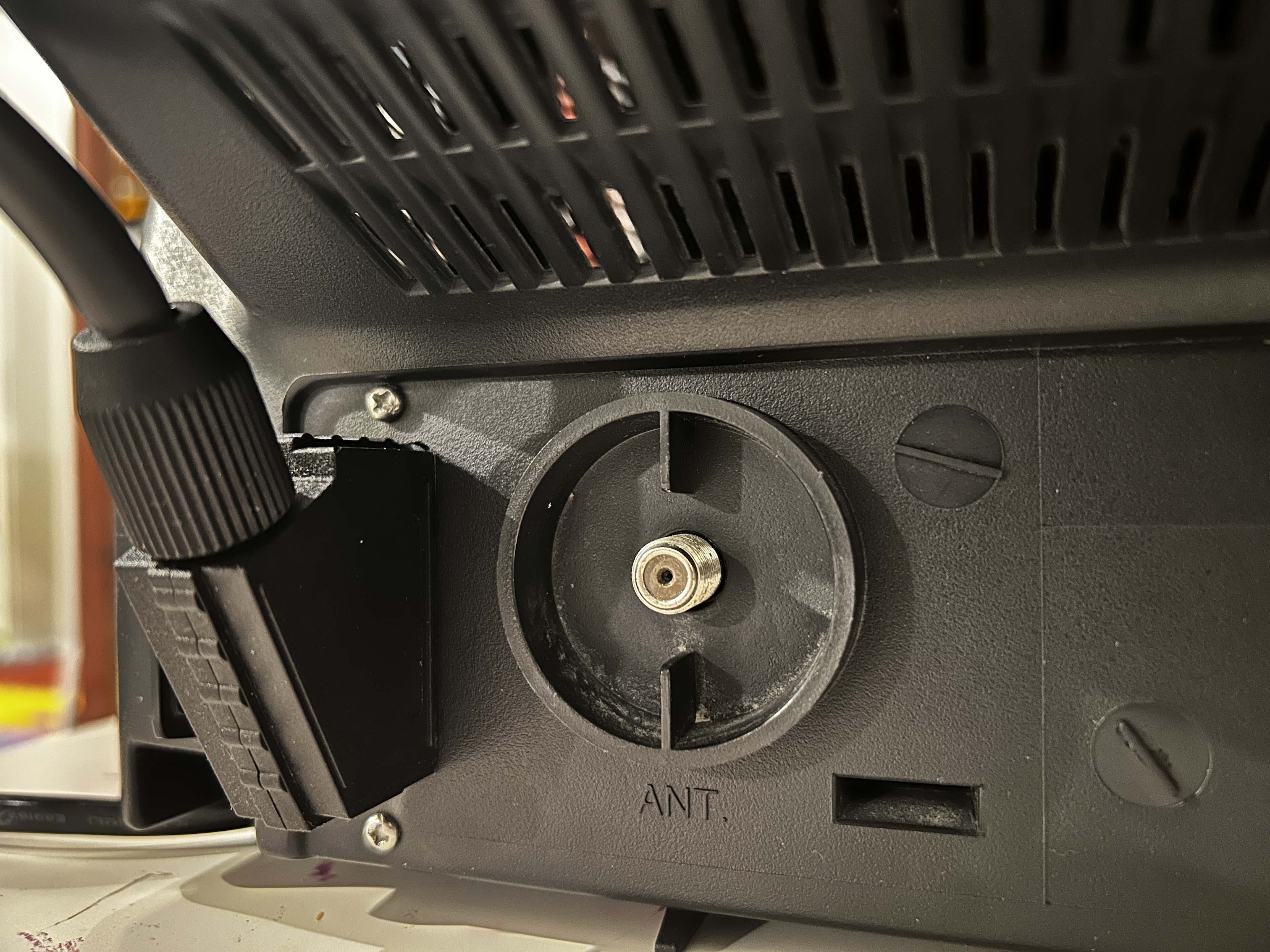
STEP 4: Attach the female SCART connector to TV
Creating a SCART cutout and mounting it is an art. I have a dedicated section for it.
SCART connector mounted 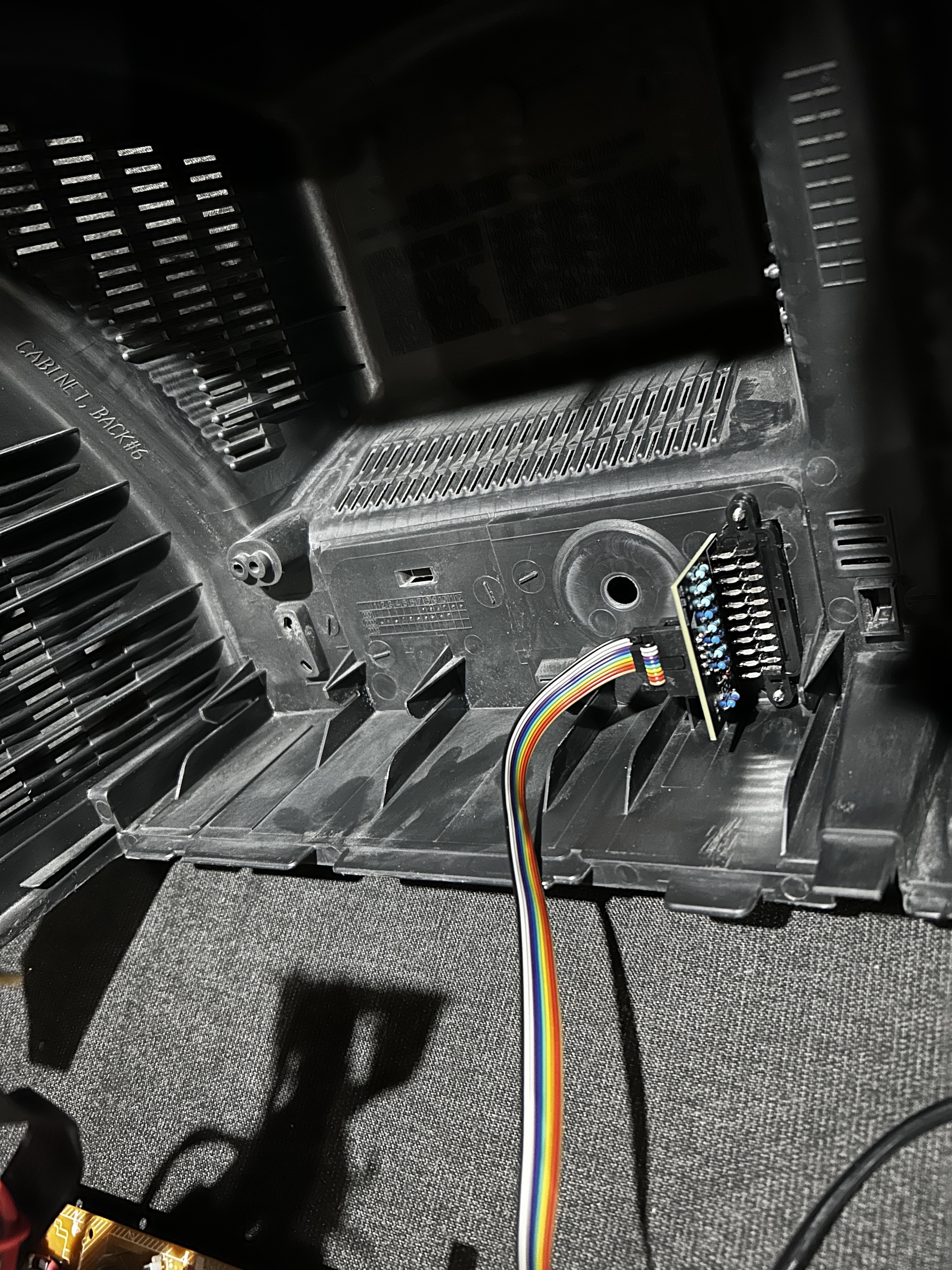
How to create and mount a SCART female plug?
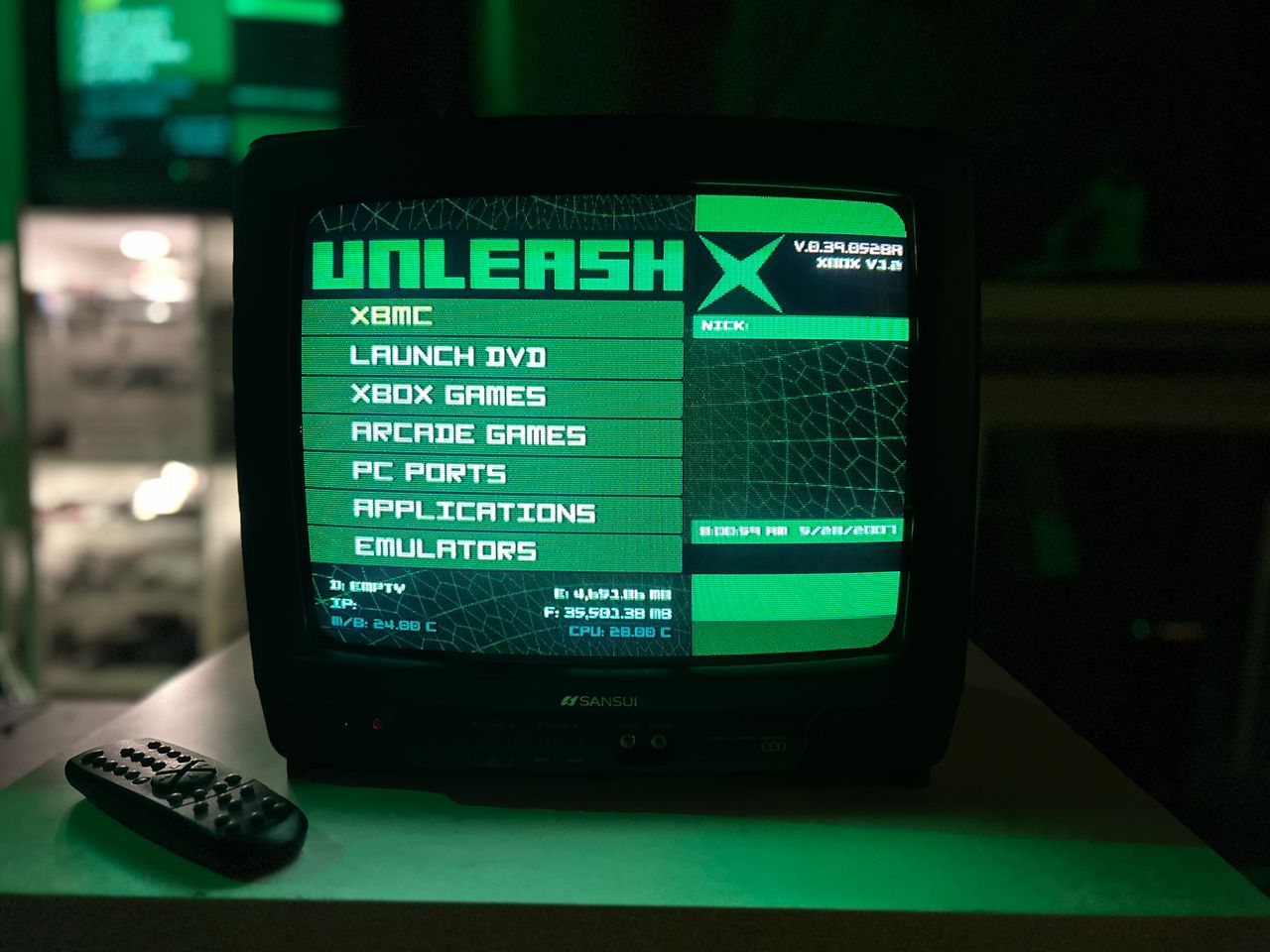
OSD mux mod 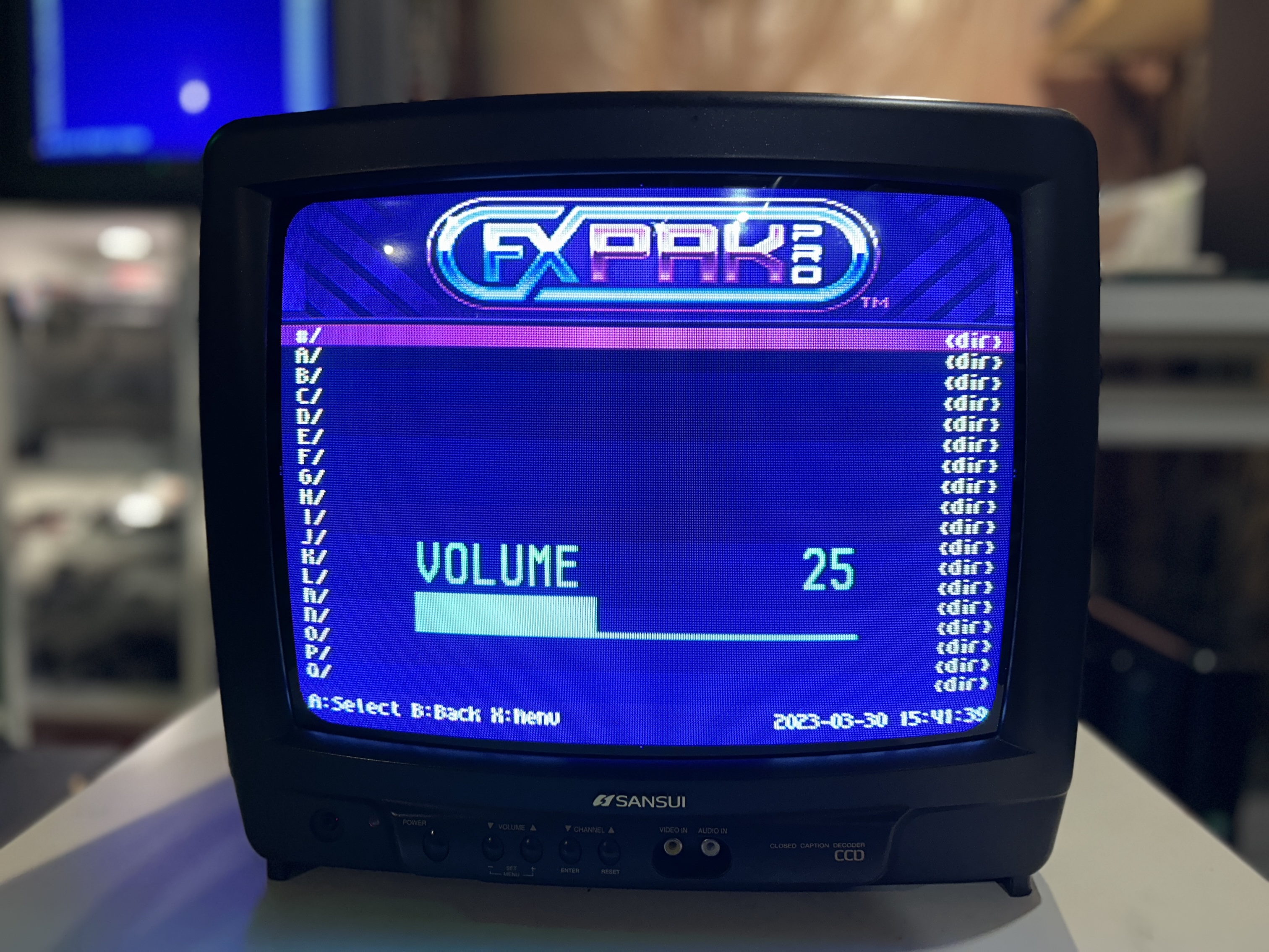
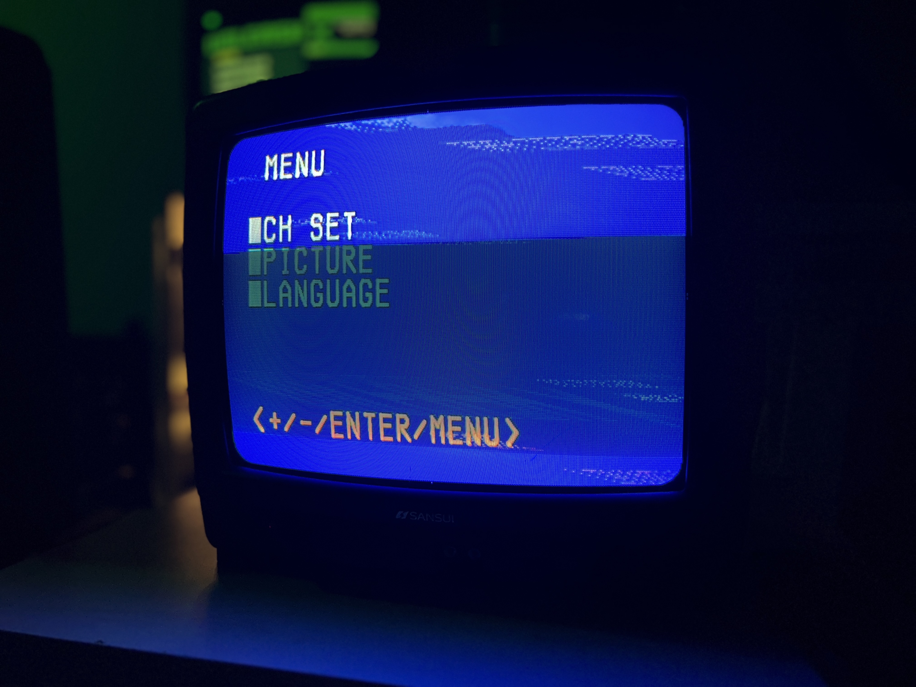
Full screen blue menu will look garbled. This is a known issue. However, it doesn't affect day-to-day functions.
Pictures
Photos by Sunthar
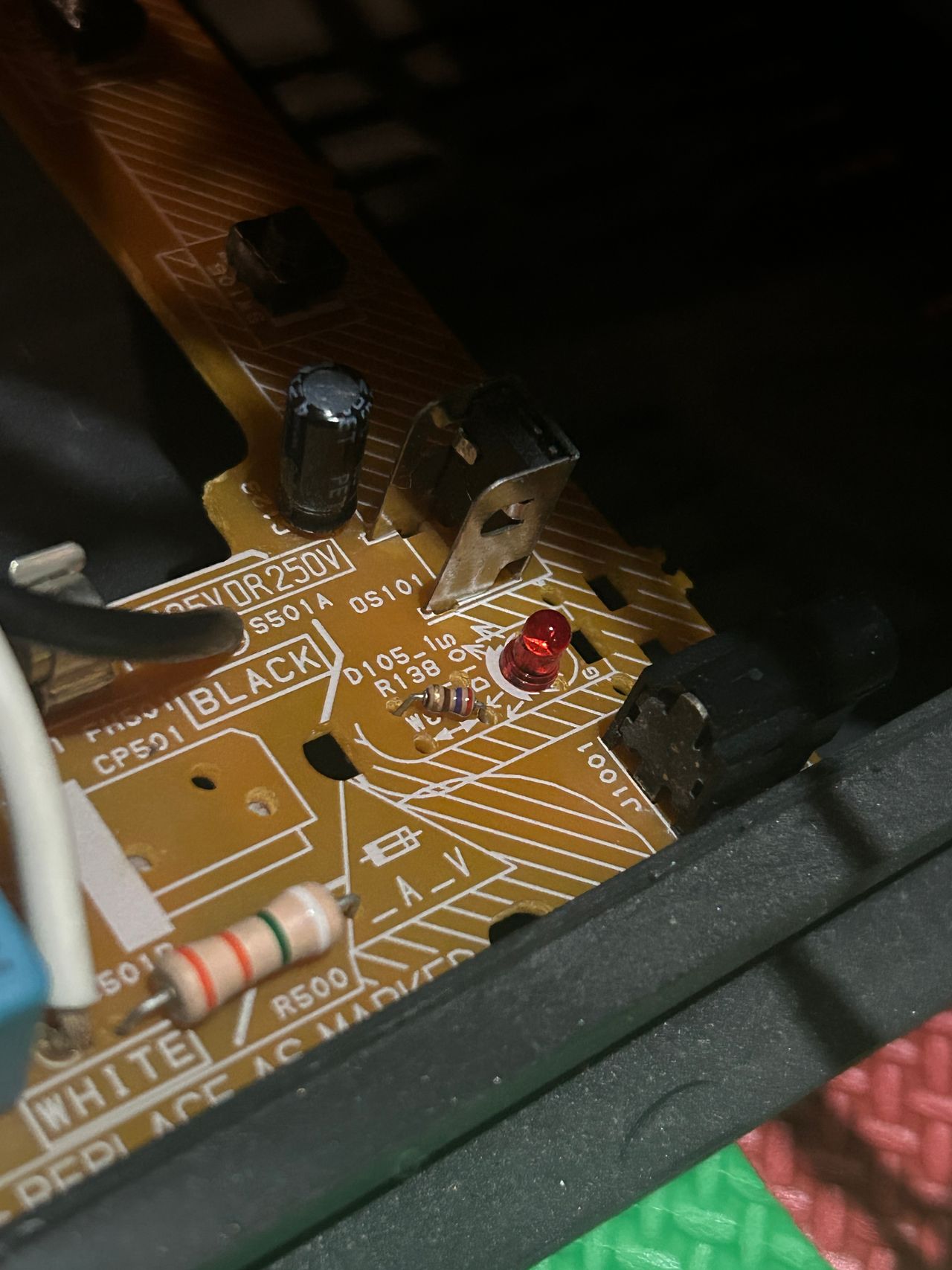
The remote control receiver on this unit wasn’t functioning. I tried several troubleshooting steps and learned a lot in the process.

Reference Photos