Toshiba 20A42
Toshiba 20A42 CRT RGB mod
The Toshiba 20A42 is a 20" CRT display with composite only input. This is a perfect candidate for RGB modification.
This is a slightly higher end set with additional inputs compared to Toshiba 20A22. I personally prefer the 20A22 casing compared to 20A42.
View full CRT details and more mod examples →
Table of Contents
Contributors
Thank you to everyone who contributed to this guide:
- Michael Lopez — showcase author
- Sunthar — author, RGB mod notes
- Zachary Durland — contributor, RGB mod and pictures
CRT safety
Caution
You can die doing this! So read carefully! CRT TV is not a toy. Do not open a CRT TV. If you don't have any prior knowledge about handling high voltage devices, this guide is not for you. CRT TV contains high enough voltage (20,000+ V) and current to be deadly, even when it is turned off.
Plan of attack
Manuals and Datasheets
Specs
- Screen Size: 20"
- Power: 90 W
- Weight: 41 lbs
Schematics
Get hold of the schematics for your TV. Understand where the RGB and Fast Blanking signals go from OSD to the Jungle (Chroma) chip.
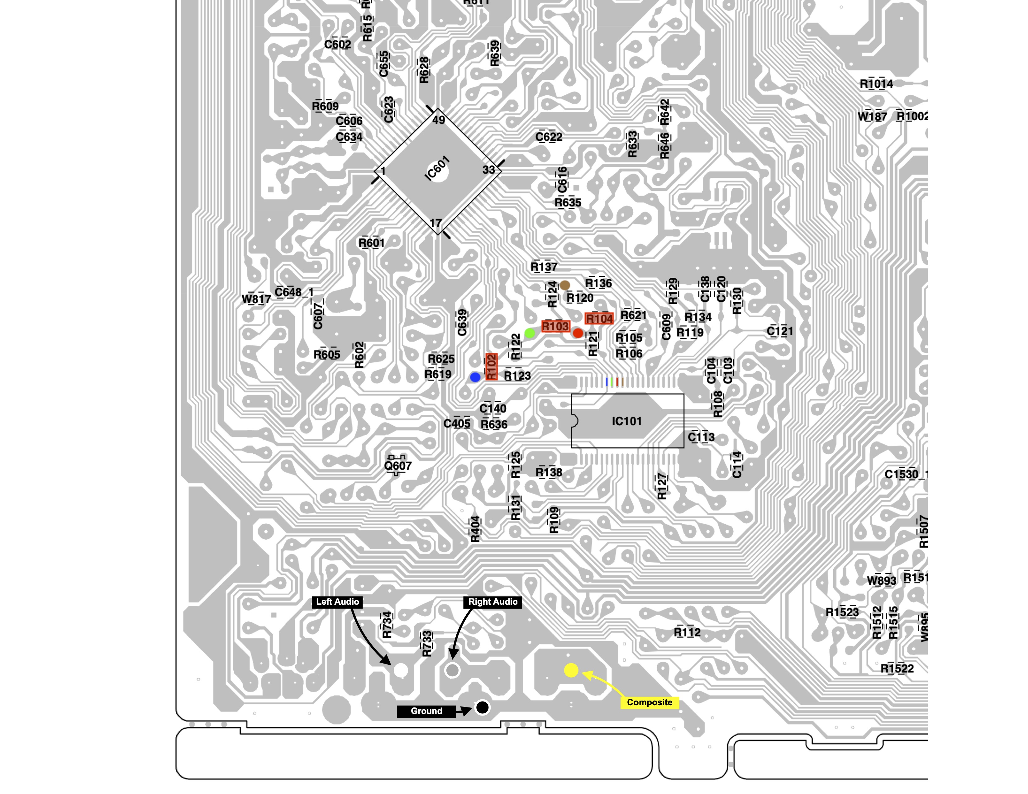
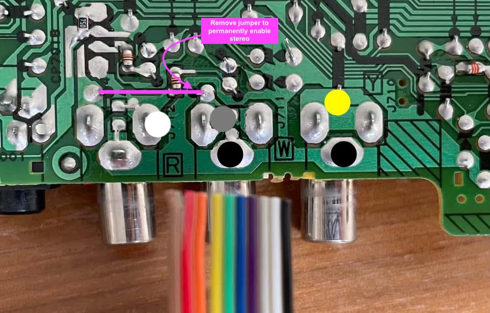
Points where the R, G, B and Blanking (brown) wires should be connected are marked on the above diagram.
RGB mux diagram
Prepare the mux diagram. If you are building your own circuit, this diagram should help.
Performing the mod
STEP 1: Remove the following components
Remove the three 680Ω, RGB resistors to ground
- R102 (680Ω)
- R103 (680Ω)
- R104 (680Ω)
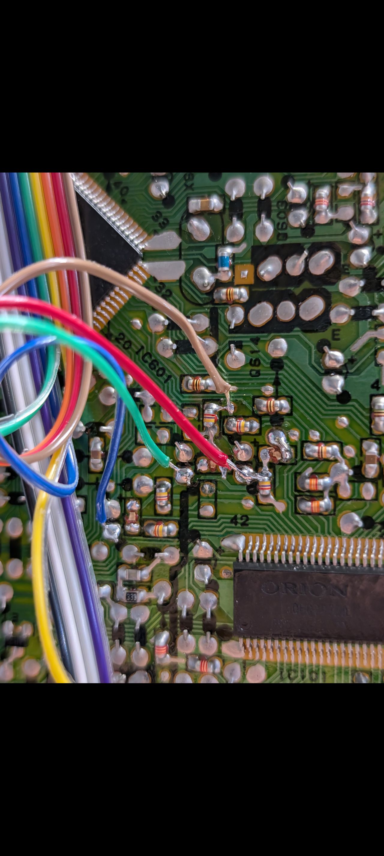
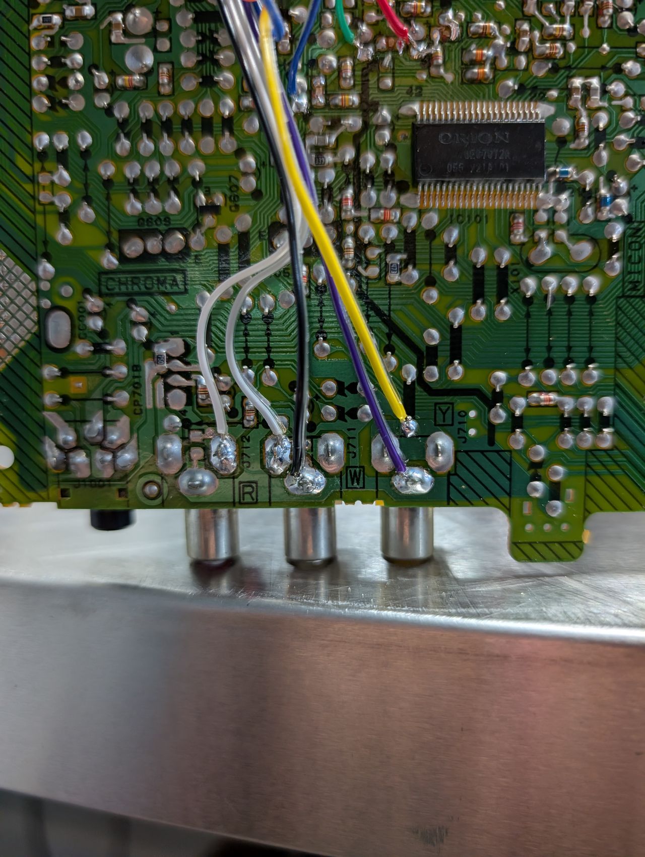
STEP 2: Connect RGBs, Blanking and Audio
![]()
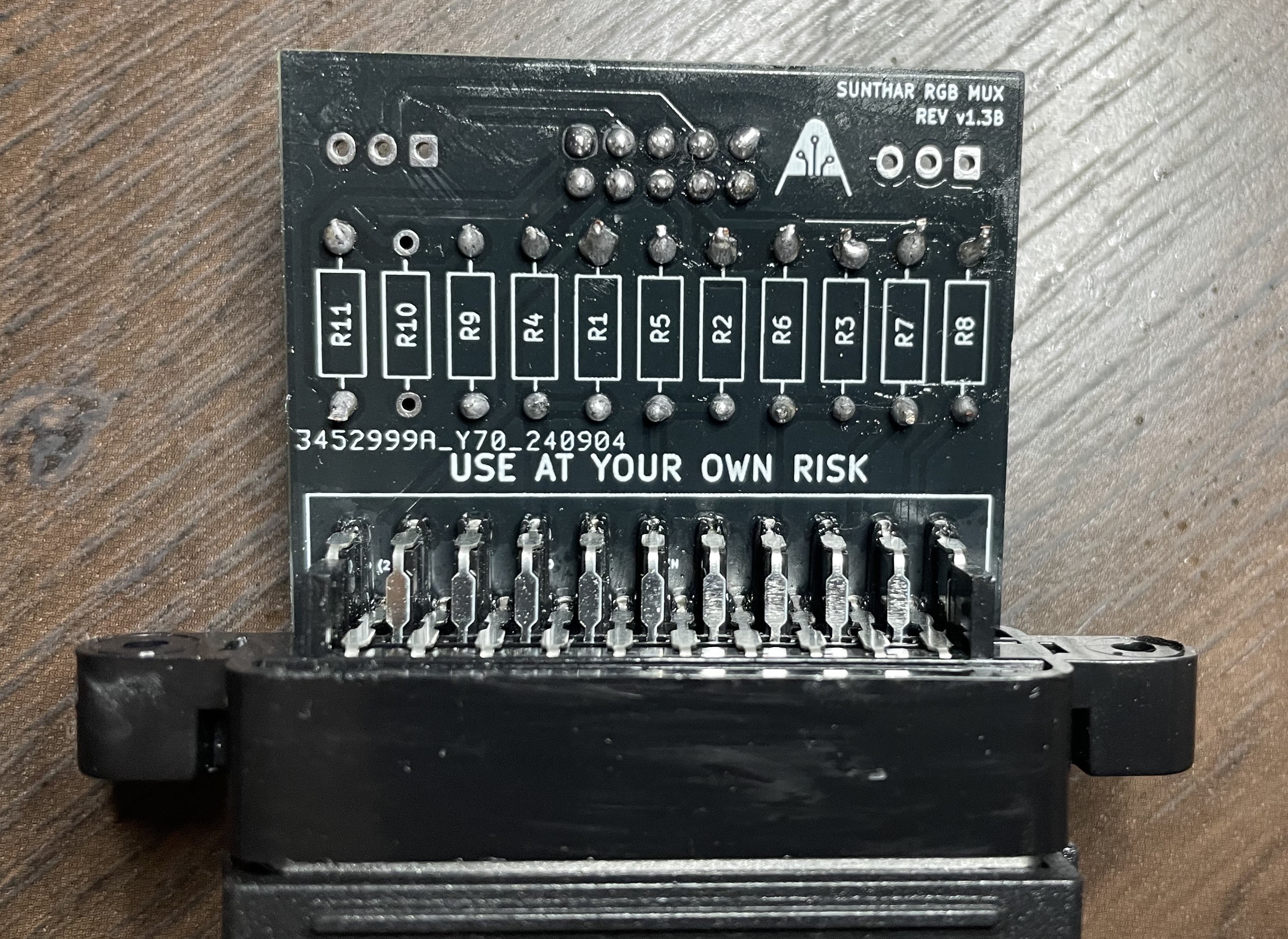
STEP 3: Build your mux circuit
This mod uses the RGB mux board. This is optional, but will make your mod easier and stable. You can also create the circuit presented in the schematics above without the board. Please also checkout the mux calculator to play with your own values.
| On Toshiba CRT Chassis | 20A42 |
|---|---|
| CRT RGB inline resistor | 4.7kΩ |
| CRT RGB ground resistors removed | 680Ω |
| 0.1μF caps replaced | No |
| Add diodes on chassis RGB lines? | No |
| Add blanking diode on chassis | No |
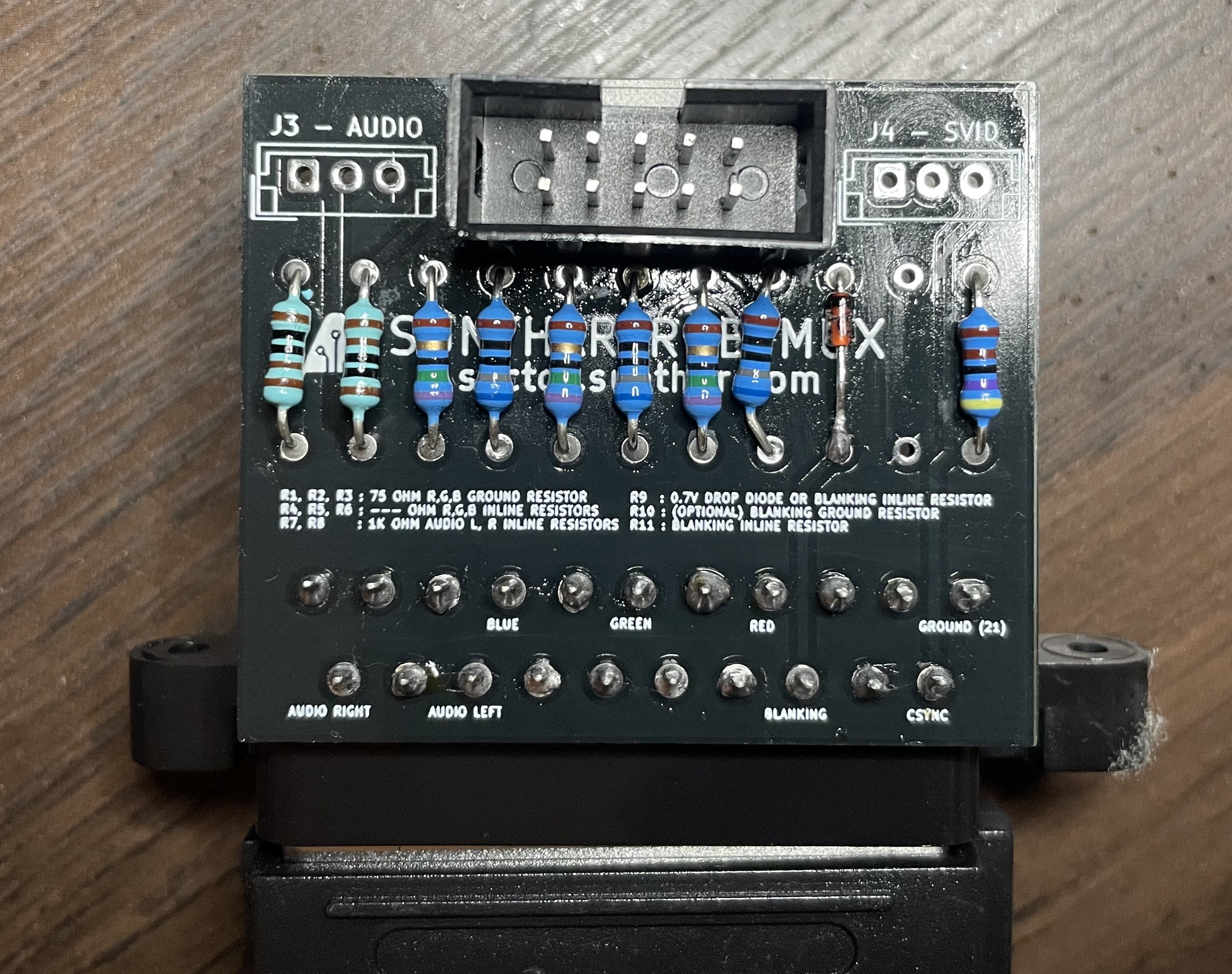
| RGB mux board | 20A42 |
|---|---|
| Mux board RGB termination (R1, R2, R3) | 75Ω |
| Mux board RGB inline resistors (R4, R5, R6) | 680Ω |
| Mux board Audio LR (R7, R8) | 1kΩ |
| Mux board blanking diode (R9) | 1N4148 |
| Mux board blanking ground resistor (R10) | open |
| Mux board blanking resistor (R11) | 4.7kΩ |
Compatible mux boards:
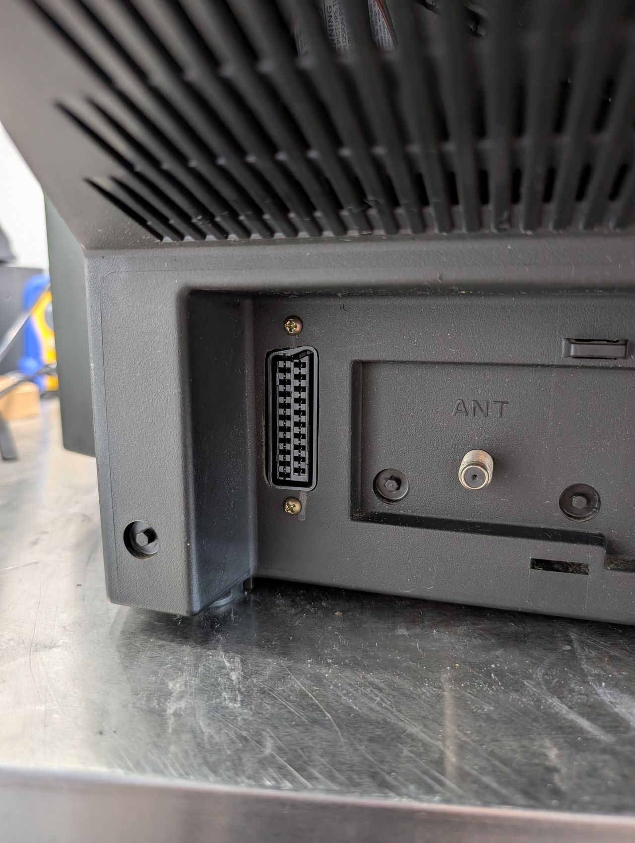
STEP 4: Attach the female SCART connector to TV
Creating a SCART cutout and mounting it is an art. I have a dedicated section for it.
How to create and mount a SCART female plug?
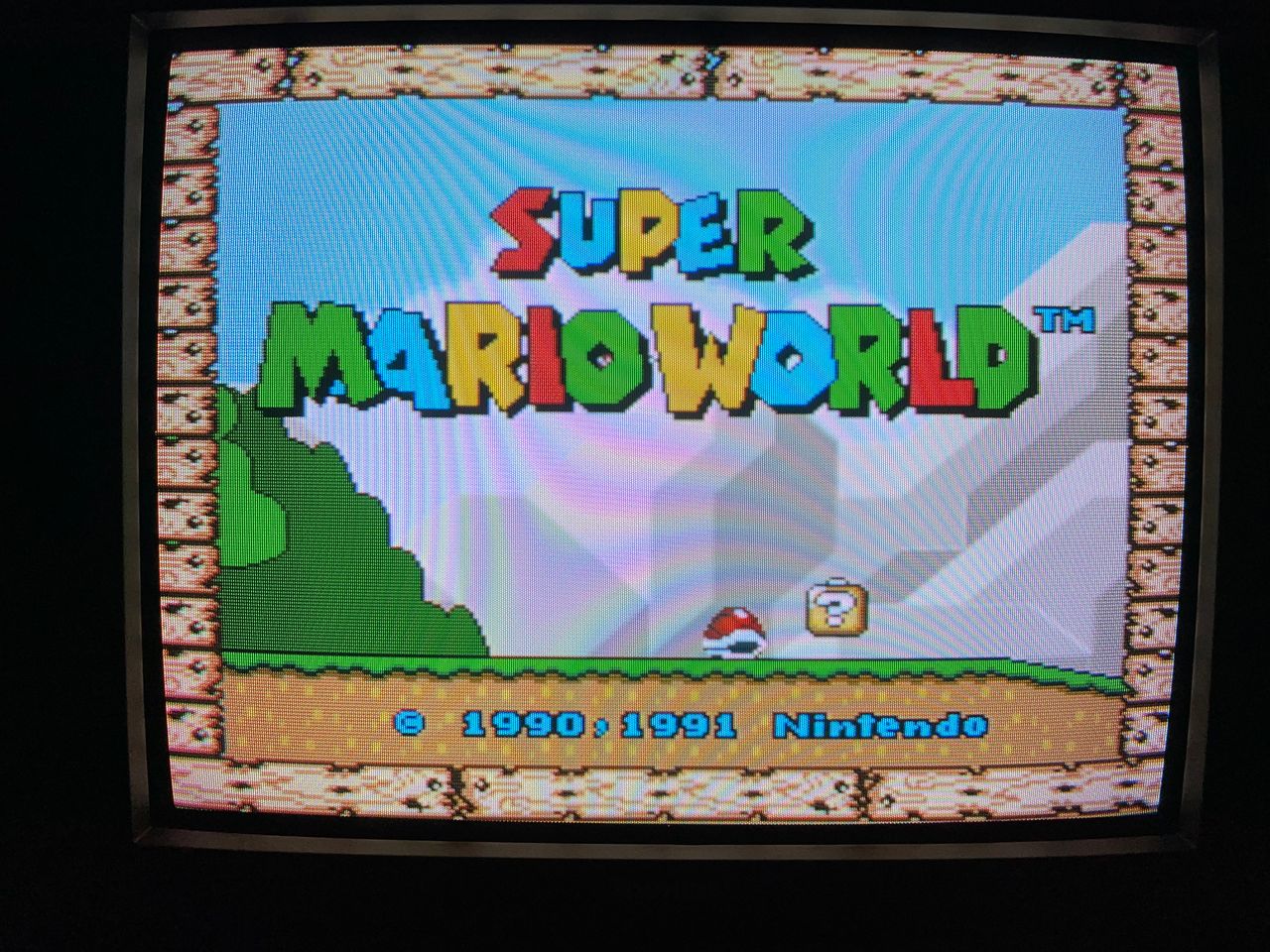
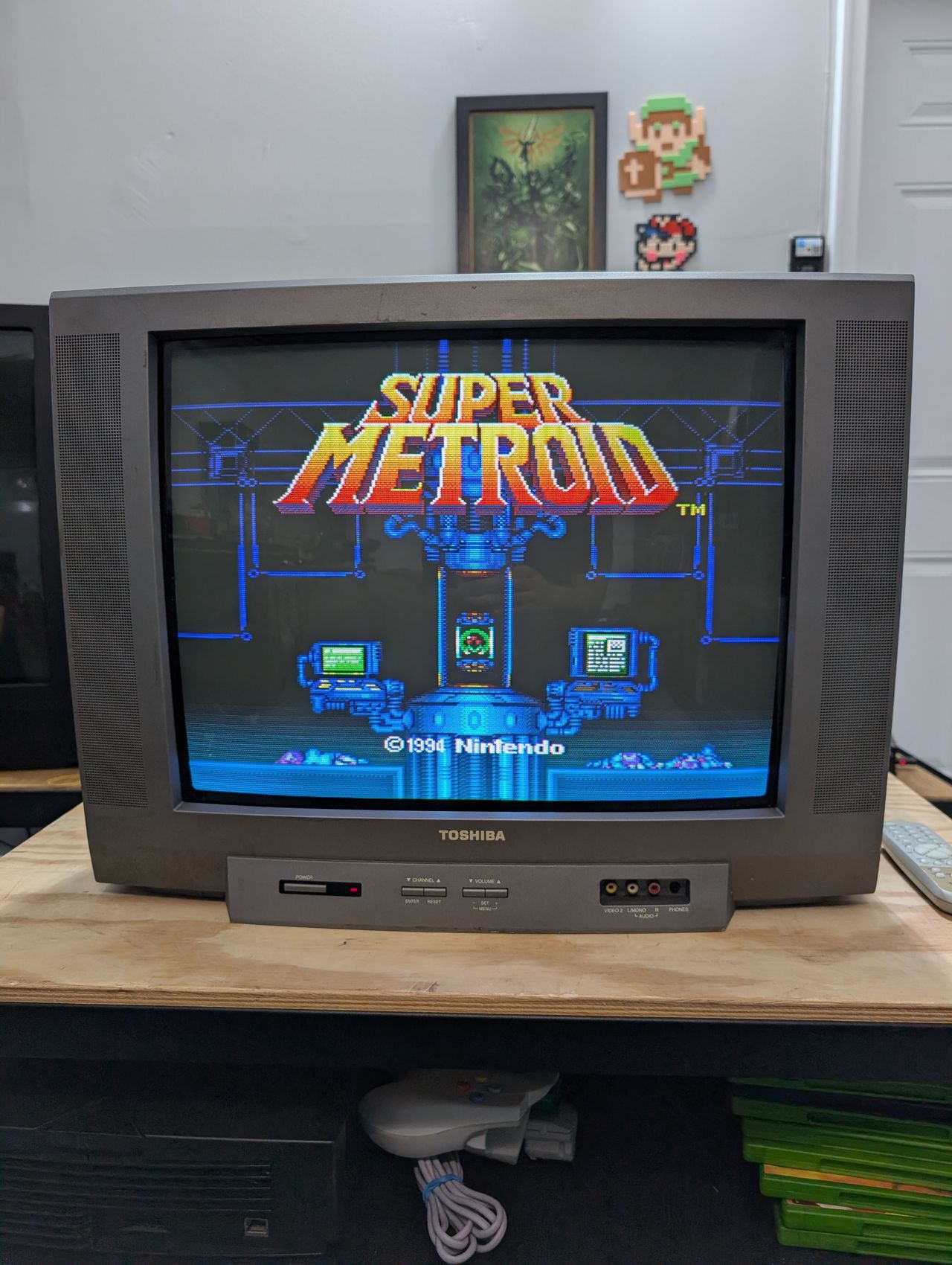
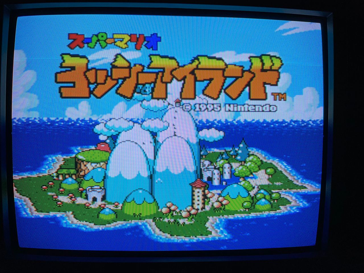
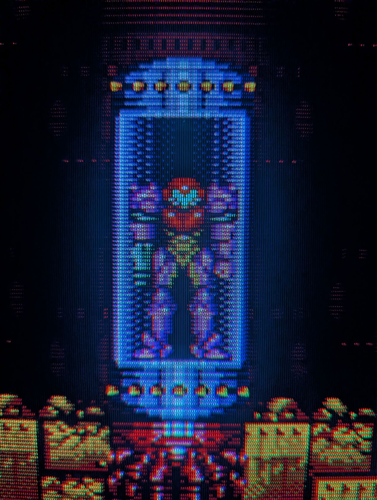
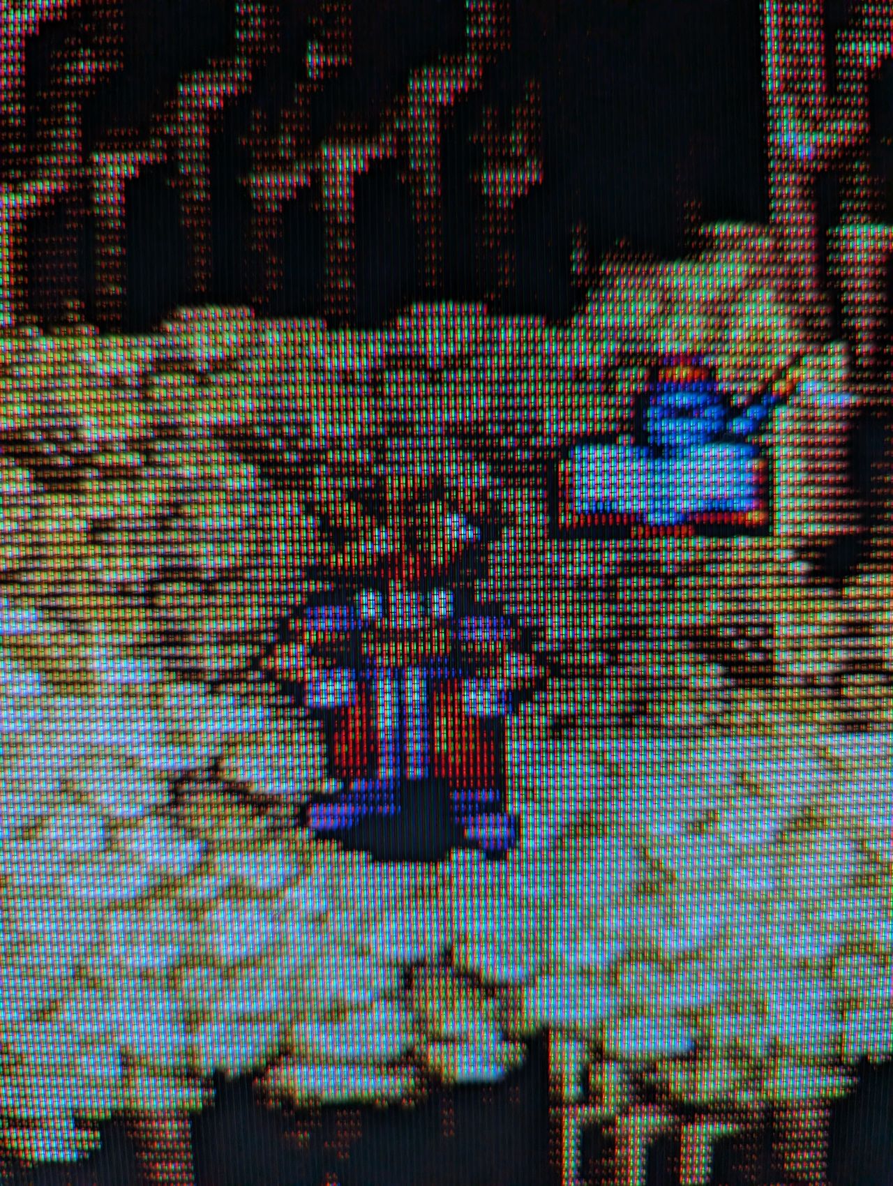
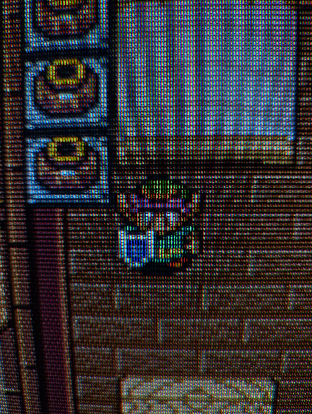
Pictures
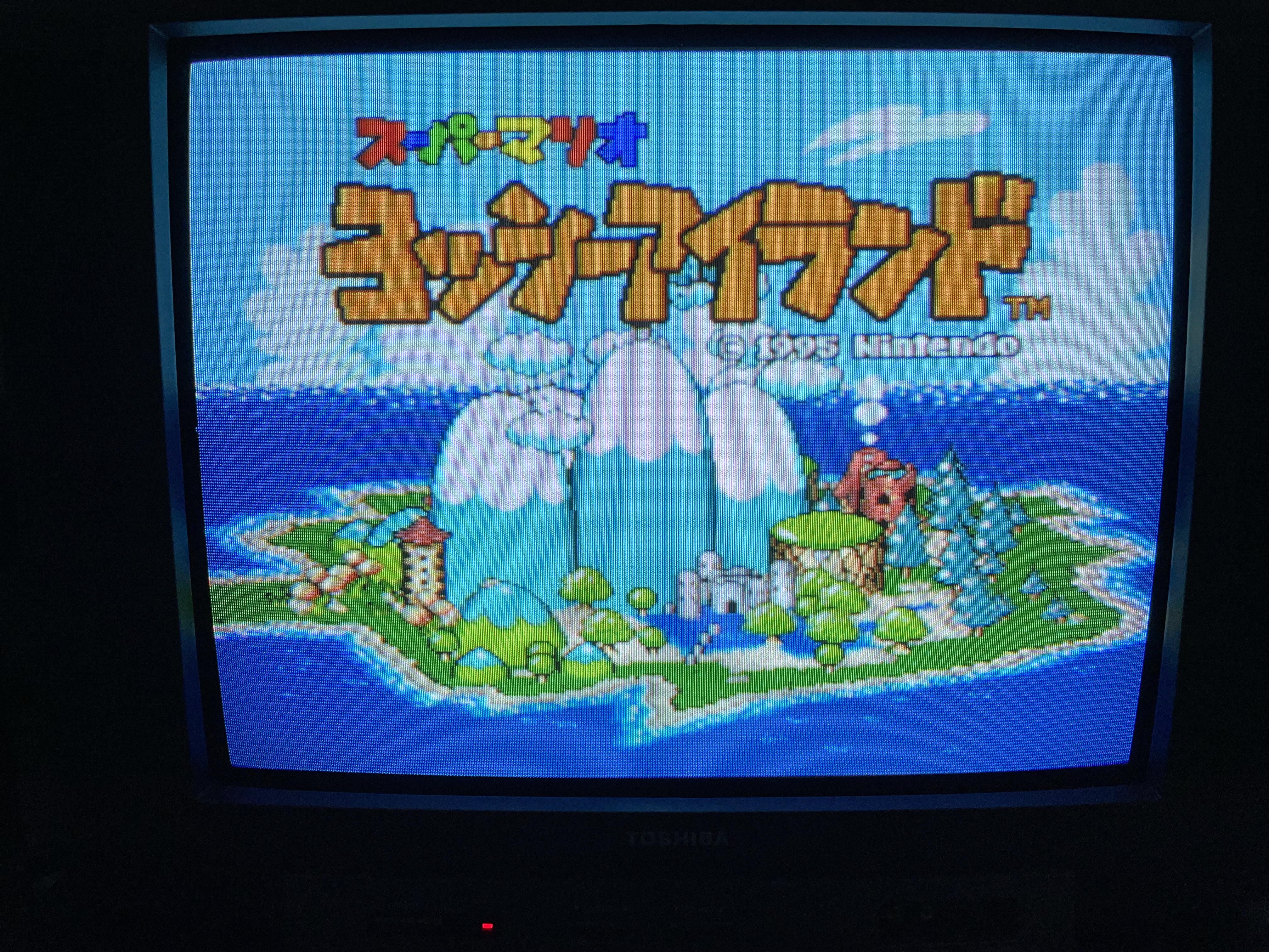

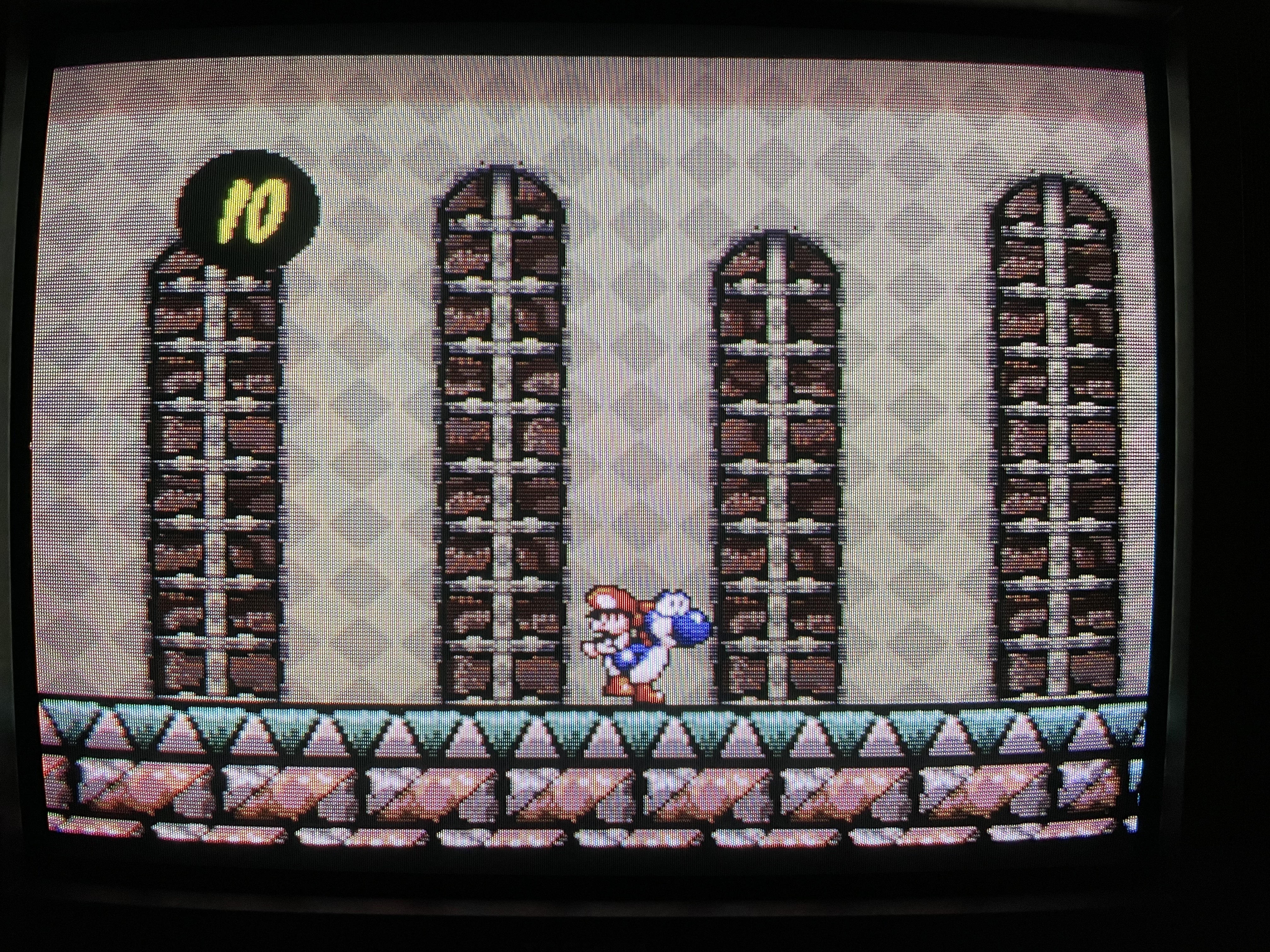
Pictures
Photos by Michael Lopez
Reference Photos