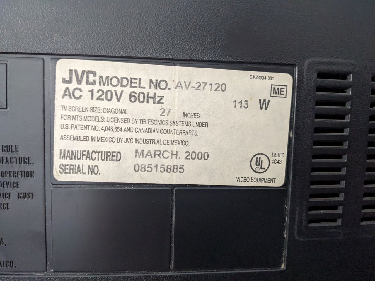
JVC AV-27120
JVC AV-27120 CRT RGB mod
In this tutorial, we will be discussing the RGB modification process for the JVC AV-27120 CRT. RGB mod for JVC AV-27220 is also very similar. This particular model boasts an exceptional tube with impressive geometry. Therefore, if you own a JVC curved set that can be RGB modified (some can't be modified), I strongly endorse trying out this modification.
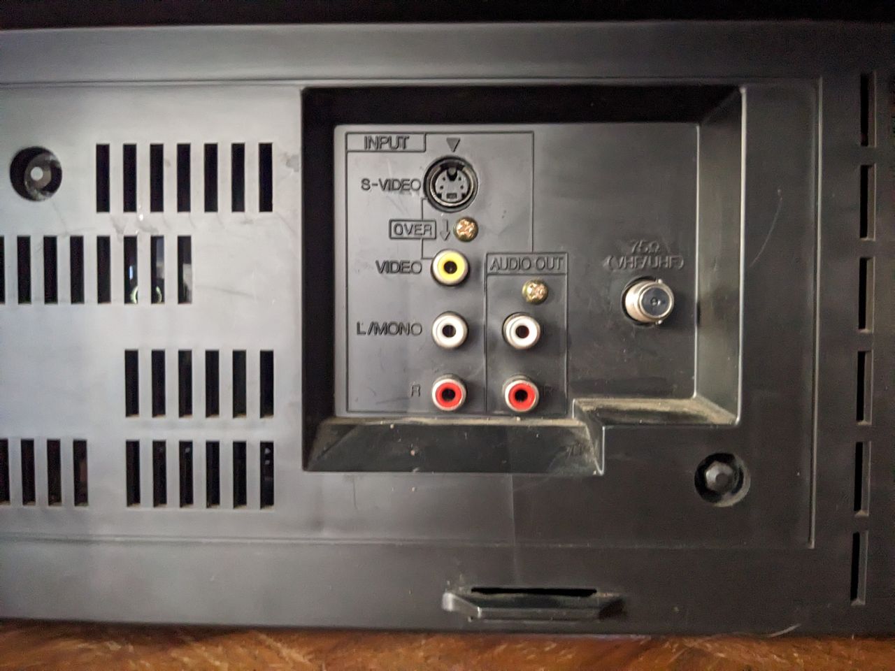
The JVC AV-27120 is a 27" consumer CRT tv released around early 2000s, featuring a curved "bubble" tube similar to the JVC D-Series. It features RF, Composite, and S-Video inputs and is a great candidate for RGB modding.
View full CRT details and more mod examples →
Contributors
Thank you to everyone who contributed to this guide:
- Martin Seibert — author, RGB mod and pictures
CRT safety
Caution
You can die doing this! So read carefully! CRT TV is not a toy. Do not open a CRT TV. If you don't have any prior knowledge about handling high voltage devices, this guide is not for you. CRT TV contains high enough voltage (20,000+ V) and current to be deadly, even when it is turned off.
Plan of attack
Manuals and Datasheets
- JVC AV-27120 Service Manual
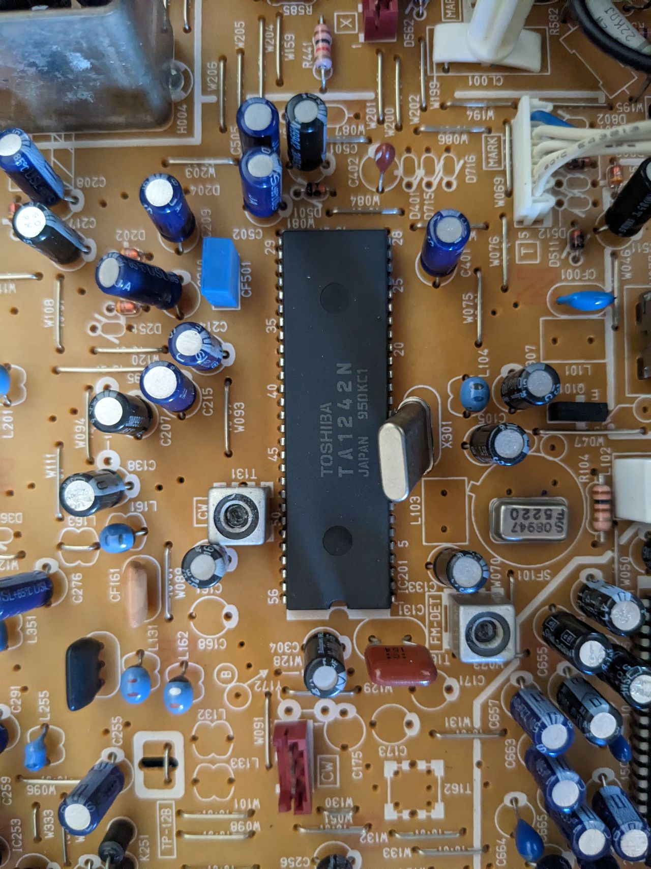
- Toshiba TA1242N Datasheet (Jungle)
- Mitsubishi M37272MA-314SP Datasheet (OSD)
Specs
- Year: 2001
- Format: NTSC
- Chassis: FV3
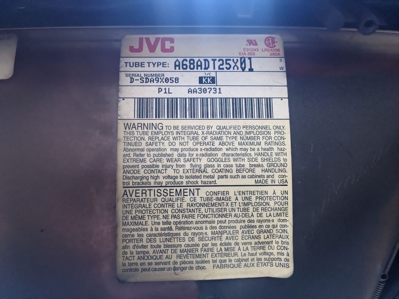
- Tube: JVC A68ADT25X01
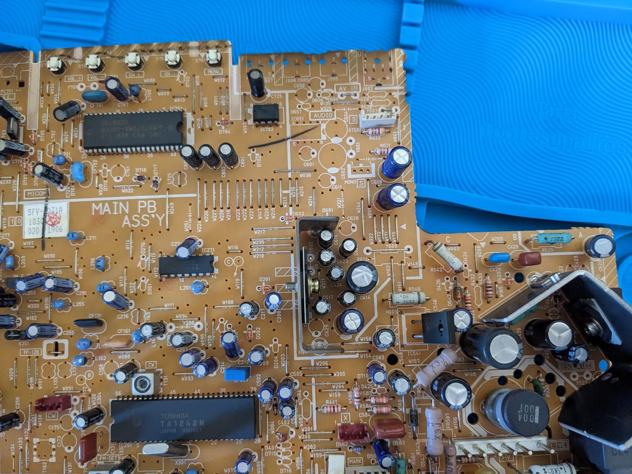
- Jungle Chip: Toshiba TA1242N
- OSD Chip: Mitsubishi M37272MA-314SP
- Screen Size: 20"
- Inputs: Composite, S-Video, RF, Component YPbPr
RGB mux diagram
Performing the mod
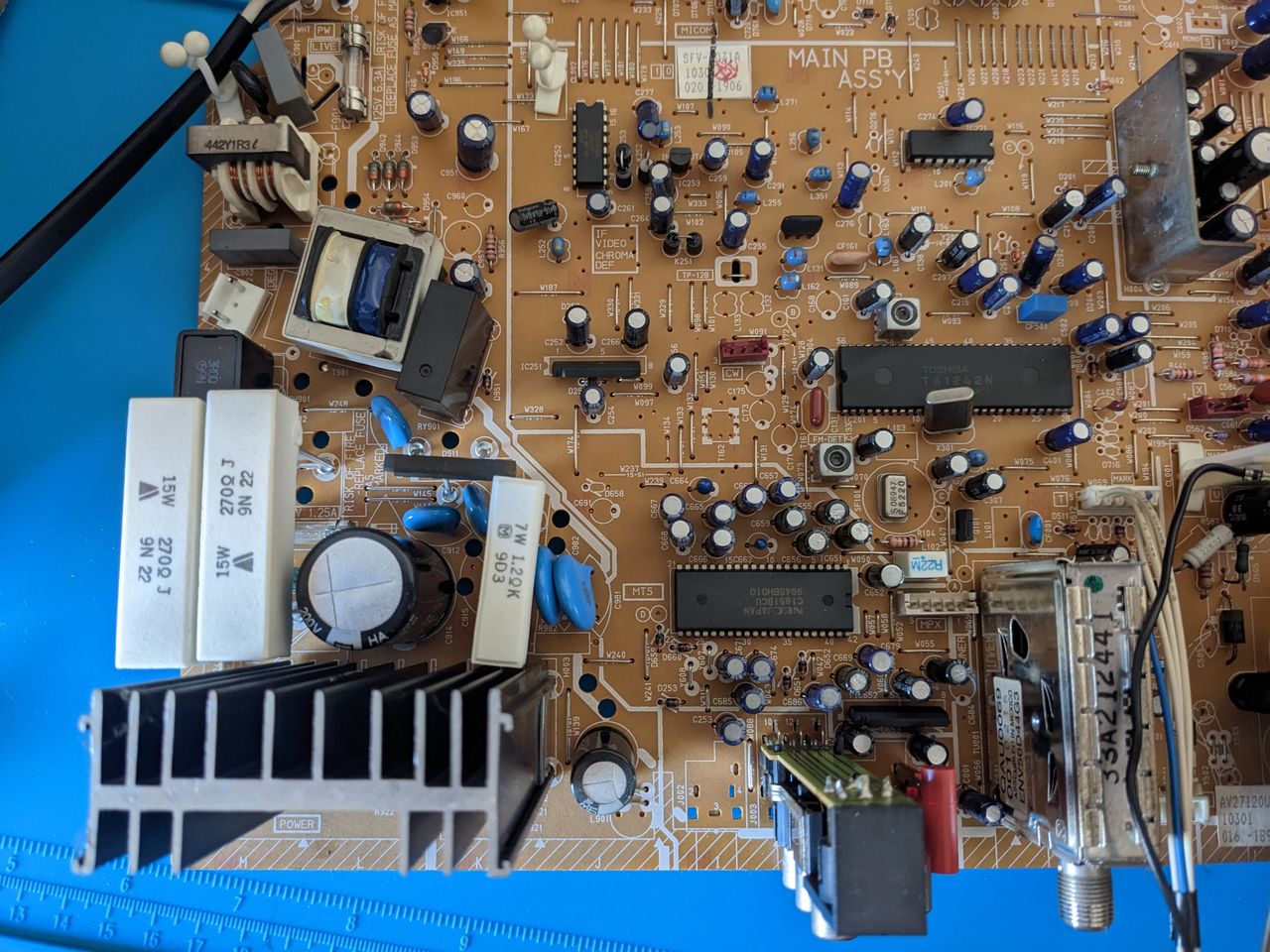
Now that you roughly know what needs to be done, prepare for the mod. Place the main chassis on a comfortable place. Make sure you are not putting pressure on the flyback or other components.
STEP 1: Remove the following components
Remove the following components. RGB resistors to the ground. Measure twice and mark before you remove.
- R738 (1.5 kΩ)
- R740 (1.5 kΩ)
- R742 (1.5 kΩ)
STEP 2: Install diodes to reduce noise
Diodes were not installed on chassis for this mod. However, it is recommended to reduce noise. See JVC-AV27230.
STEP 3: Connect RGBs, Blanking and Audio
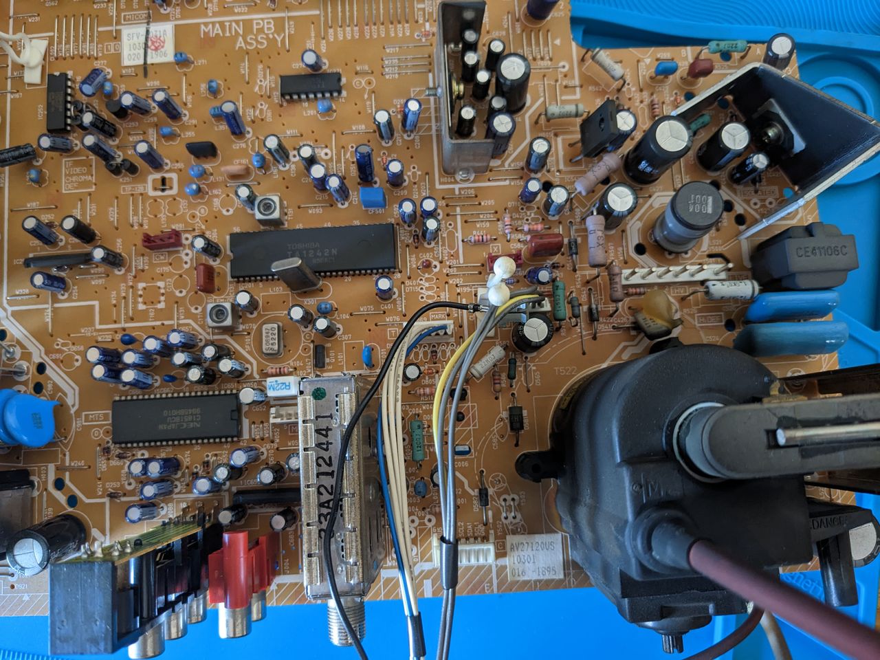
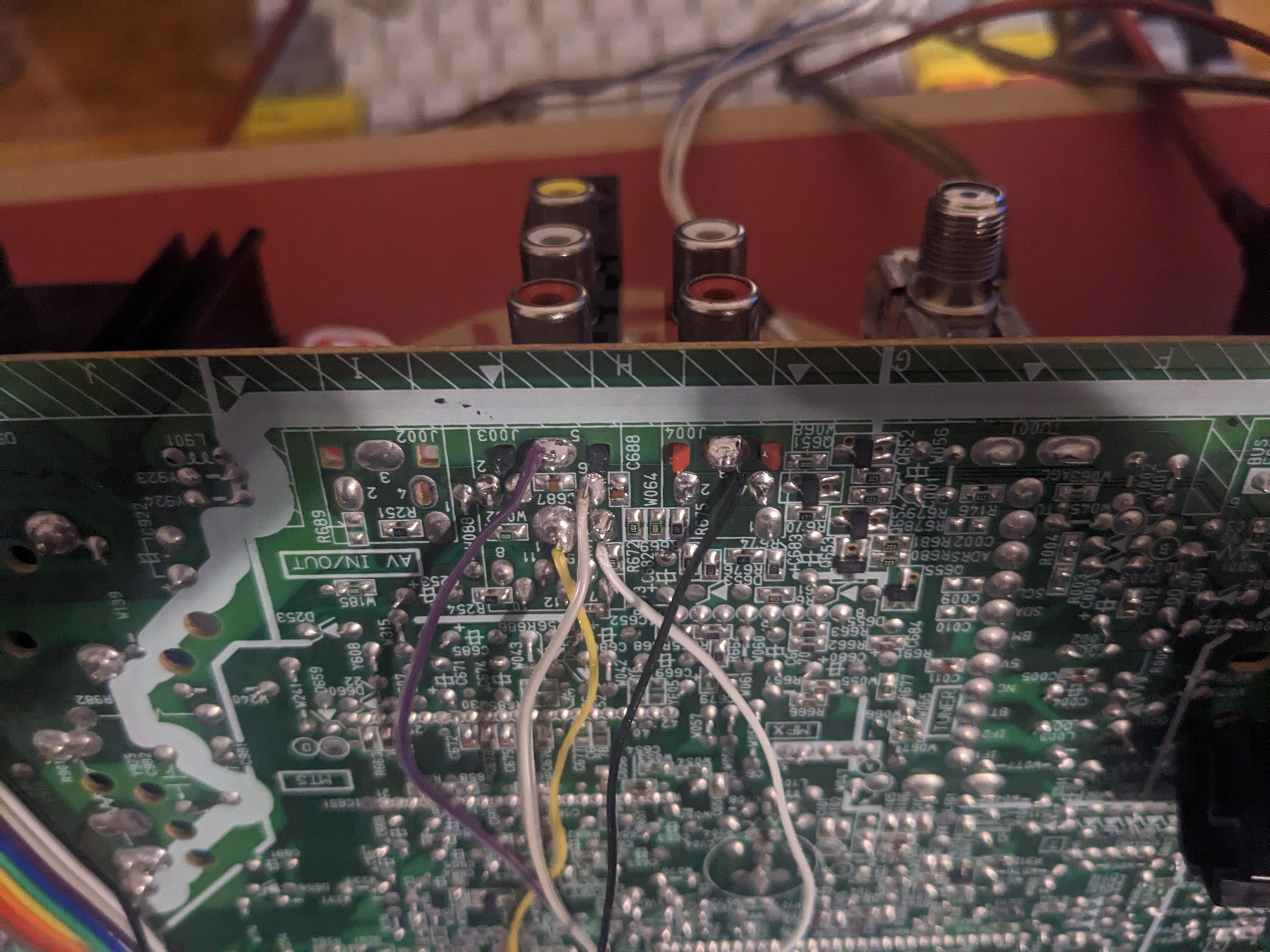
The picture presented below depicts the appropriate placement for soldering the R, G, B, and blanking wires onto the solder side of the chassis. It is crucial to solder them on the correct side of the diode installation location, as illustrated in the image. Please remember, the below R, G, B, blanking solder locations for wiring would be different if you were to install diodes.
![]()
The sync was connected to the composite input that was already 75Ω terminated, while the audio was connected to the corresponding left and right audio inputs. It's important to remember that in order for the stereo sound to function properly, a dummy RCA must be inserted into the right channel's red audio RCA port.
Black wire is the common ground for both audio and video. Purple and orange wires are for auxillary purposes and can be grounded (suppose you want to add a switch based mod or you can also use them for S-Video mod).
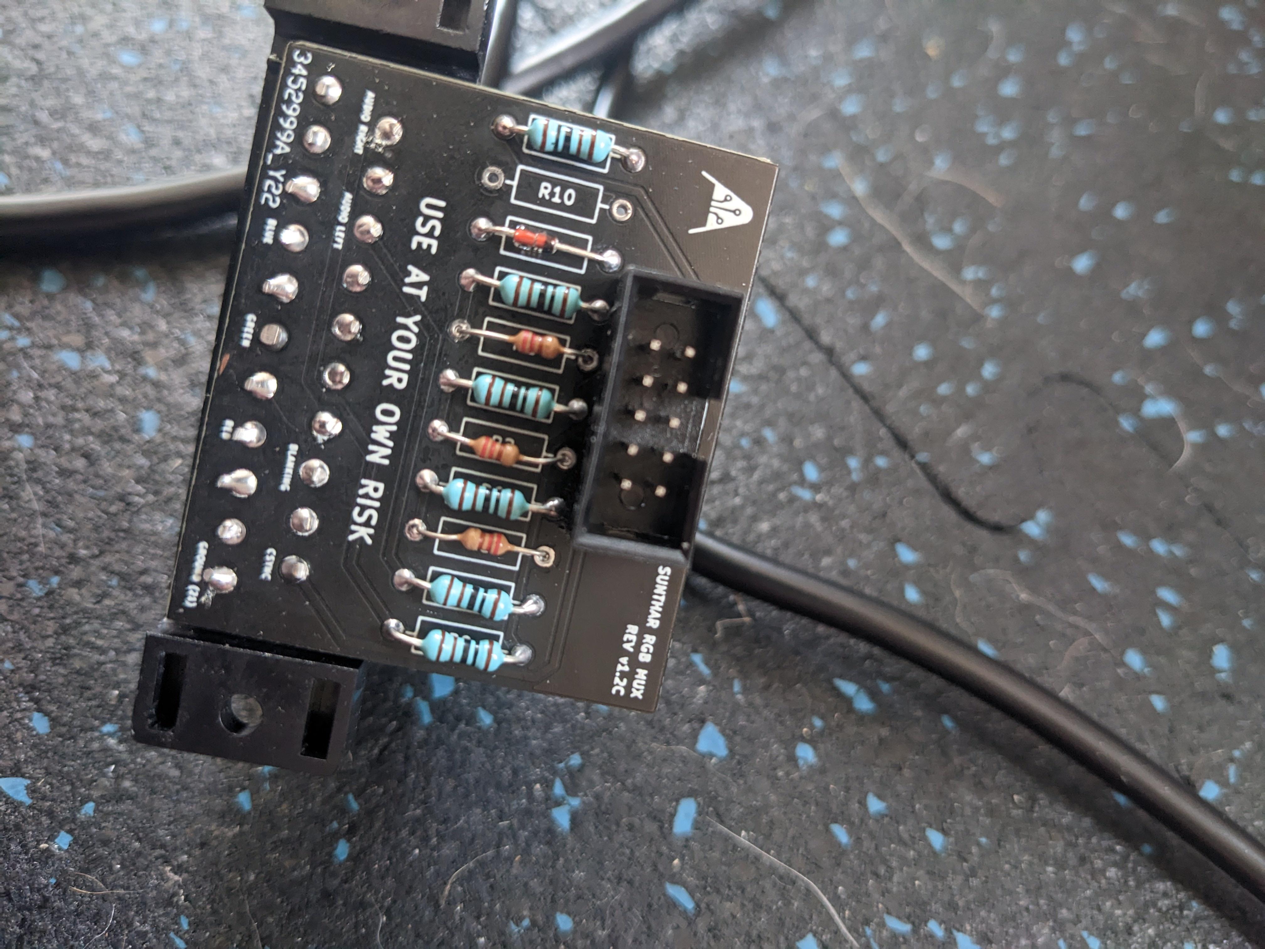
STEP 4: Build your mux board
This mod uses the RGB mux board. This is optional, but will make your mod easier and stable. You can also create the circuit presented in the schematics above without the board. Please also checkout the mux calculator to play with your own values.
| Component | Value |
|---|---|
| RGB/OSD inline resistor (chassis) | 4.7kΩ |
| Removed RGB/OSD resistor (chassis) | 1.5kΩ |
| RGB inline diode method (chassis) | Yes |
| RGB termination (R1, R2, R3) | 220Ω |
| RGB inline (R4, R5, R6) | 1kΩ |
| Audio LR (R7, R8) | 1kΩ |
| Blanking Ground Resistor (R10) | 4.7kΩ |
| Blanking Resistor (R11) | 1kΩ |
This mod uses the RGB mini mux board (Rev C)
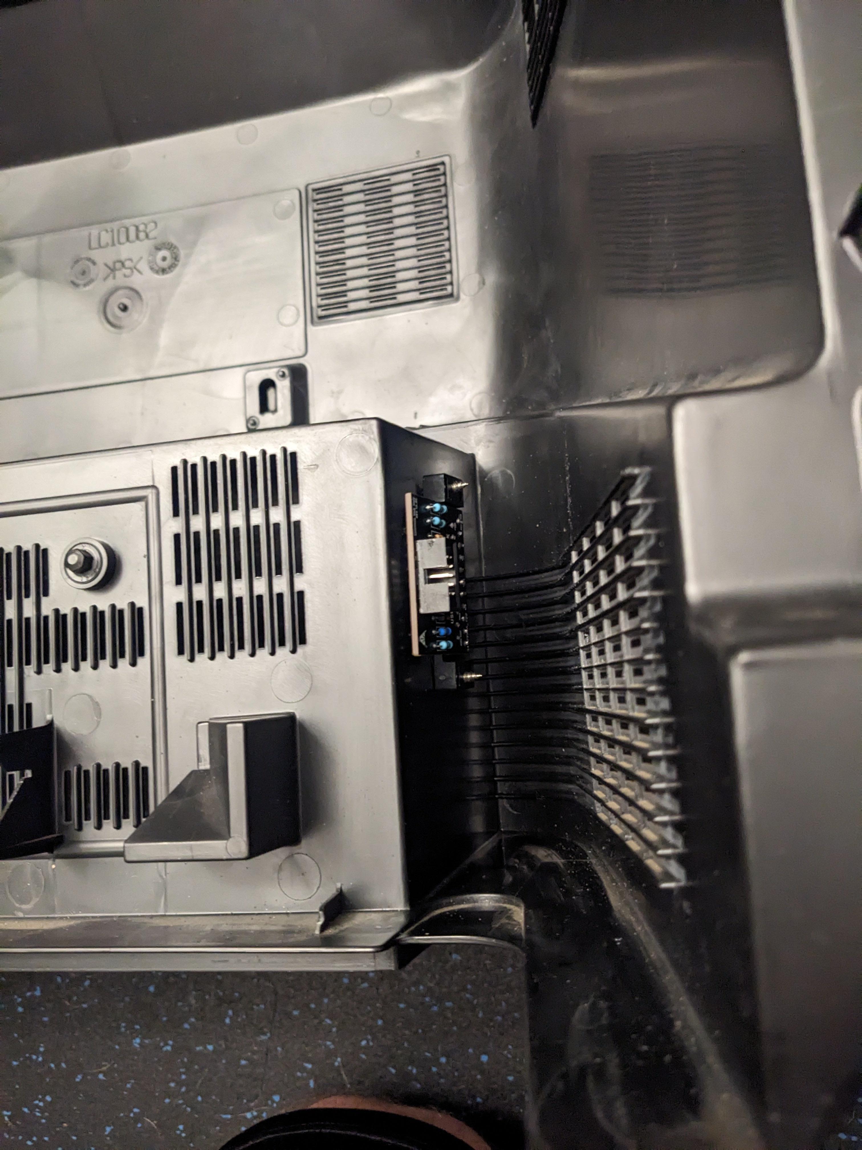
STEP 5: Attach the female SCART connector to TV
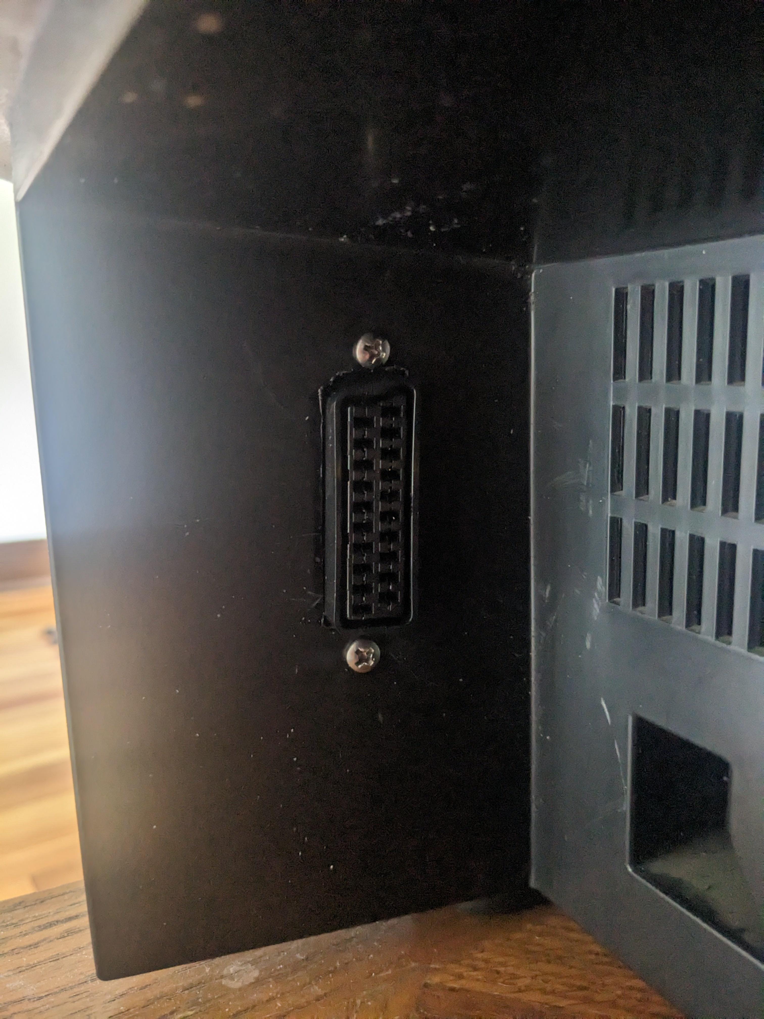
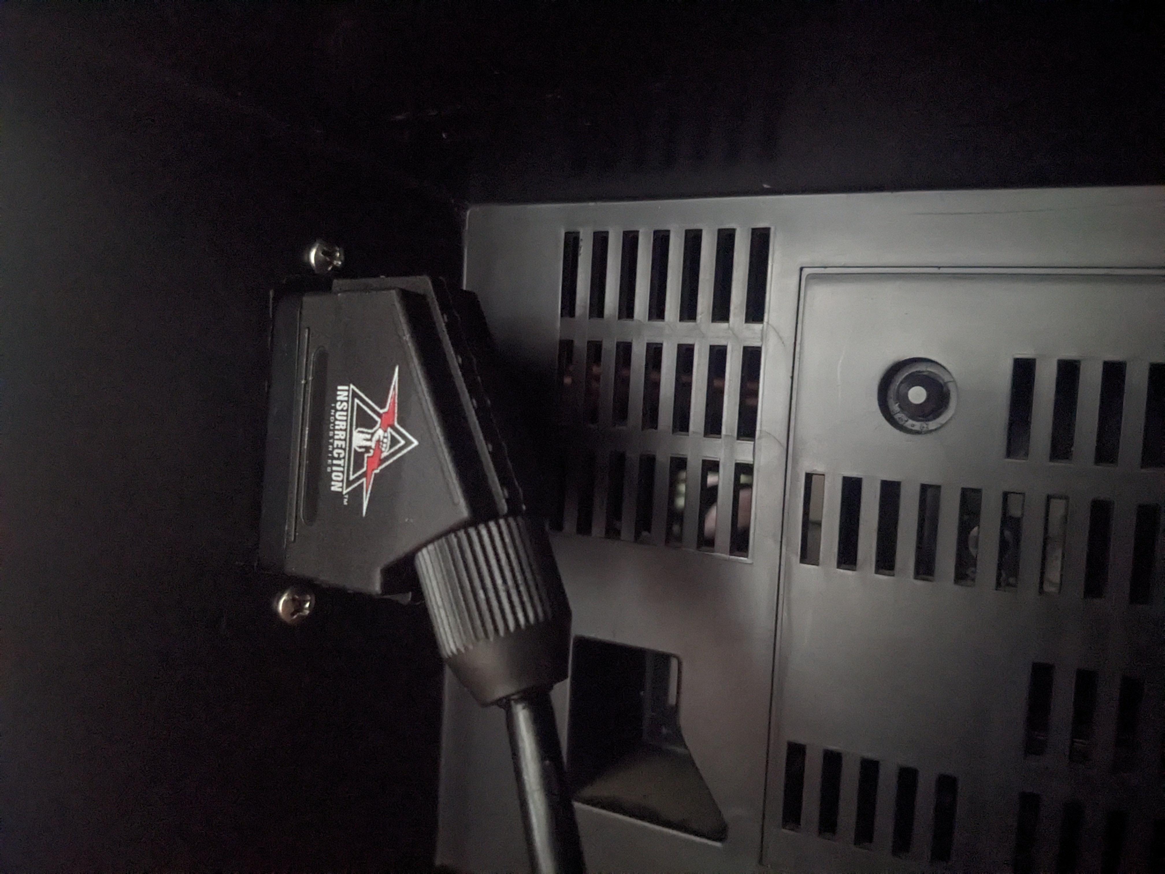
Creating a SCART cutout and mounting it is an art. I have a dedicated section for it.
How to create and mount a SCART female plug?
Remote control and service menu
- Press the
SLEEP TIMERkey and set theSLEEP TIMERfor0 MIN - While the
SLEEP TIMERis displaying on the CRT, do the below - Immediately press the
DISPLAYkey and theVIDEO STATUSkey of the remote control unit at the same time. - Then enter the
SERVICE MENUscreen shown in figure.
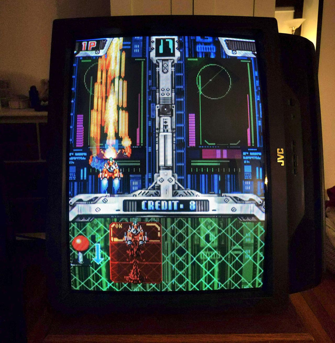
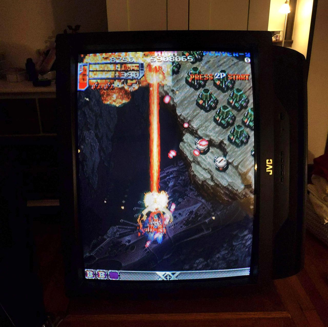
Sonic 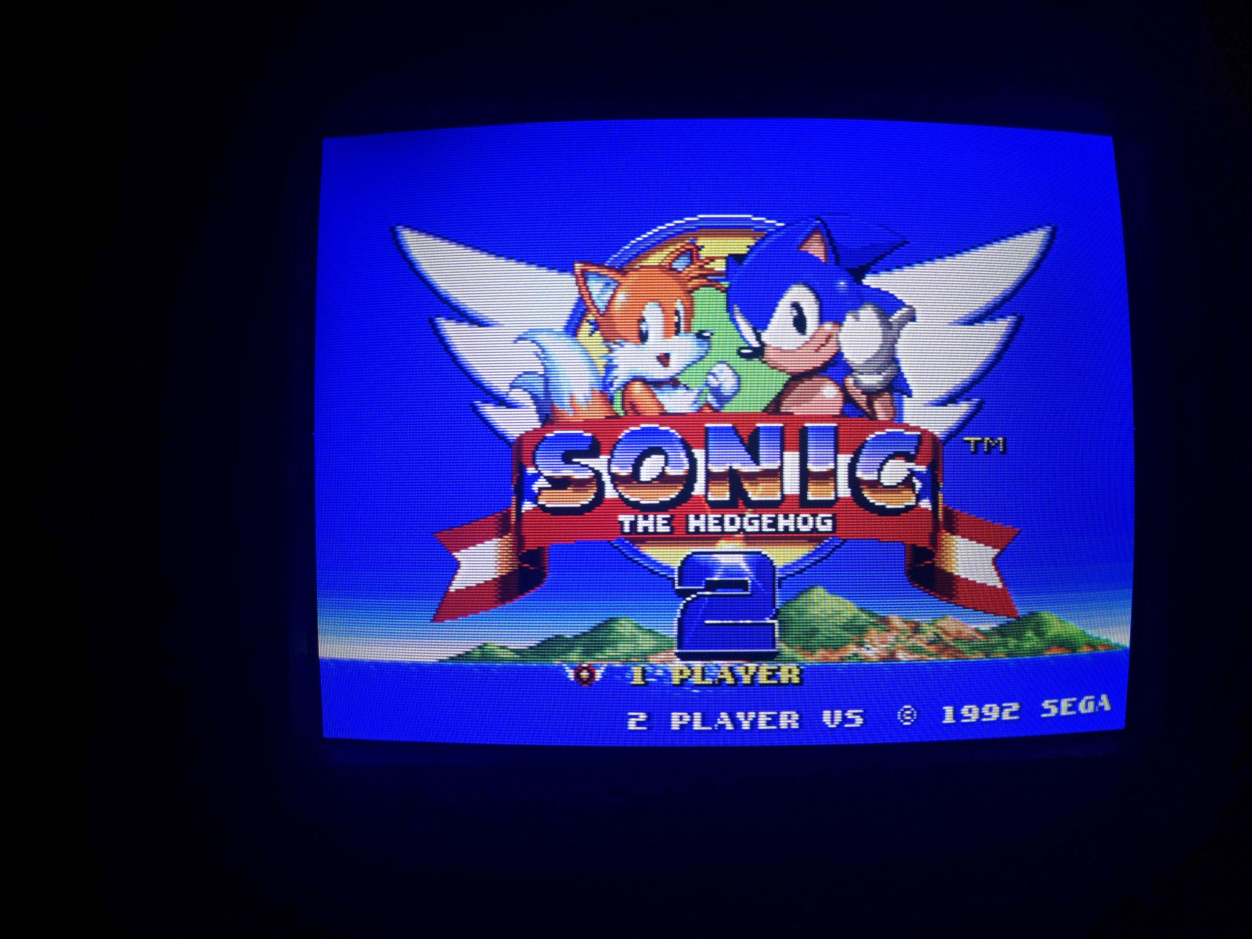
SMPTE 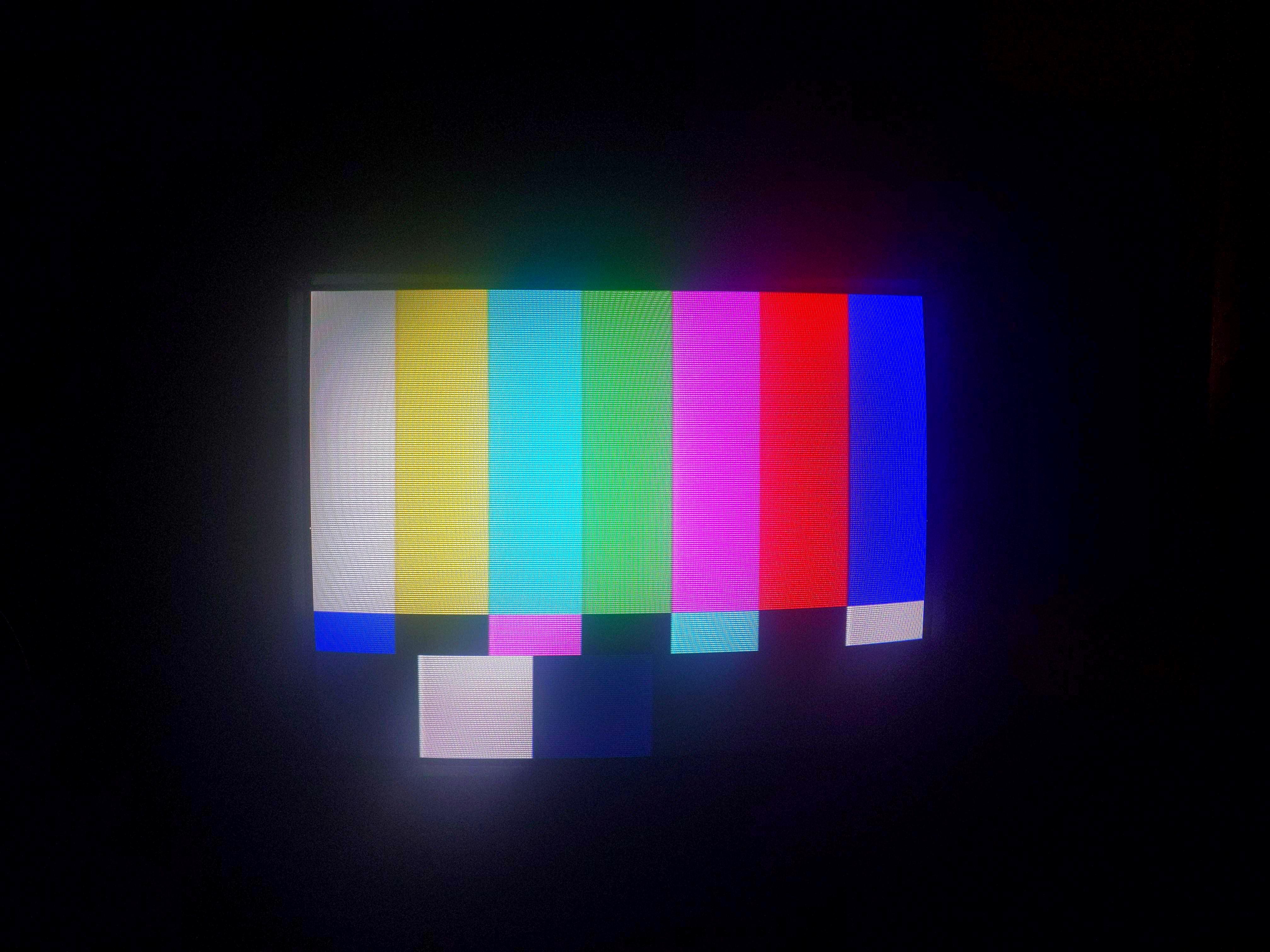
240p Grid 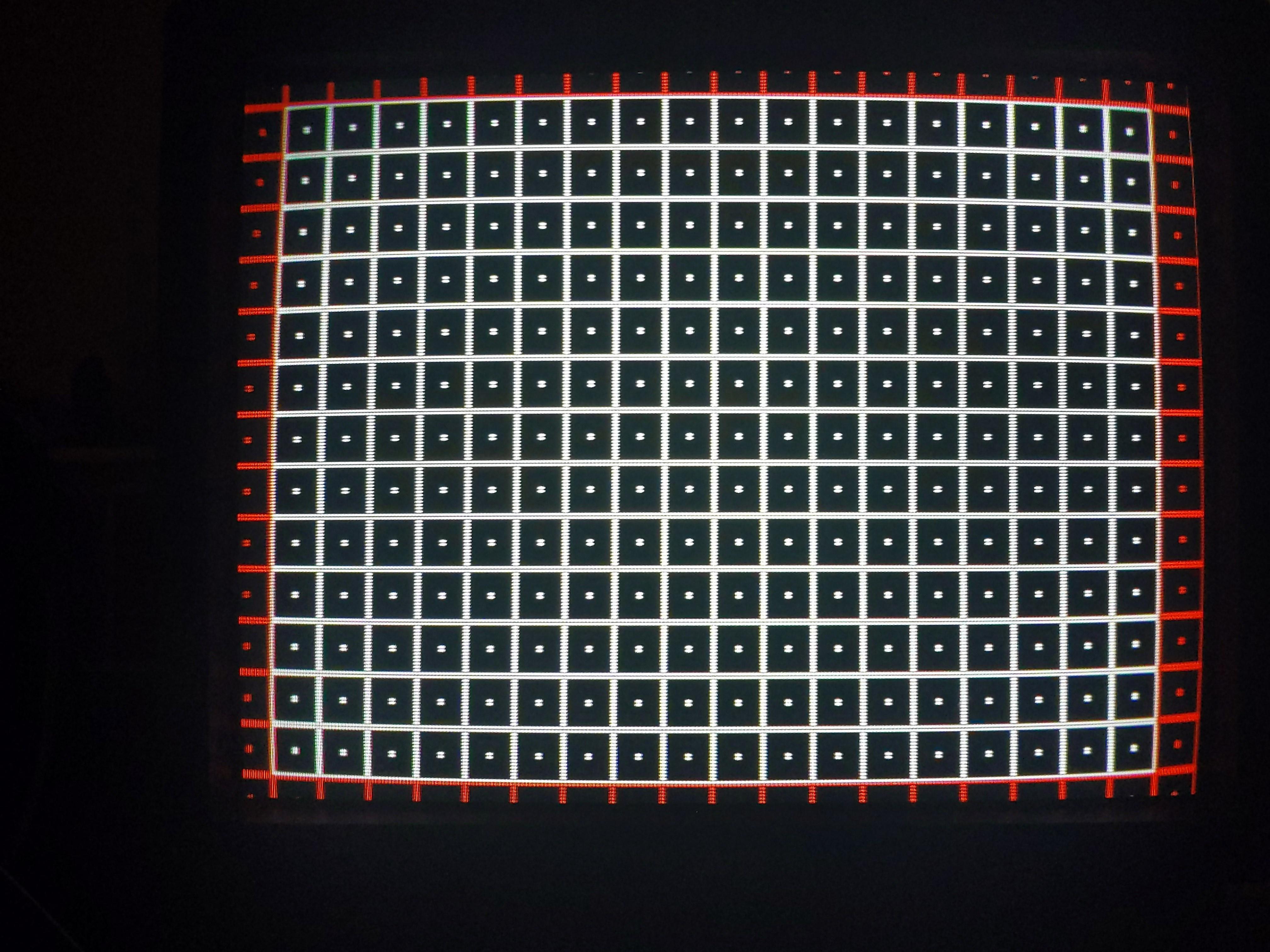
Pictures
Reference Photos