Sony (AA-2D) KV-32V40
Sony (AA-2D) KV-32V40 CRT RGB mod
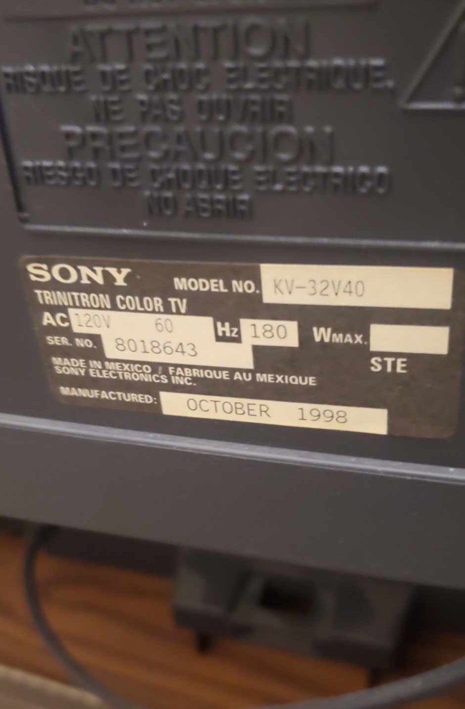
The Sony KV-32V40 is a 32" curved glass Trinitron CRT television released in the late 1990s, built on Sony's AA-2D chassis.
This set is RGB moddable.
View full CRT details and more mod examples →
Contributors
Thank you to everyone who contributed to this guide:
- Advaned Video, Lousiana — contributor, RGB mod and pictures
CRT safety
Caution
You can die doing this! So read carefully! CRT TV is not a toy. Do not open a CRT TV. If you don't have any prior knowledge about handling high voltage devices, this guide is not for you. CRT TV contains high enough voltage (20,000+ V) and current to be deadly, even when it is turned off.
Plan of attack
Manuals and Datasheets
Specs
- Manufactured: USA (1998)
- Format: NTSC
- Chassis: AA-2D
- Tube: Sony Trinitron
- Jungle Chip: Sony CXA2025AS
- OSD Chip: CXP858-002S
- Screen Size: 35"
- Power: 180 W
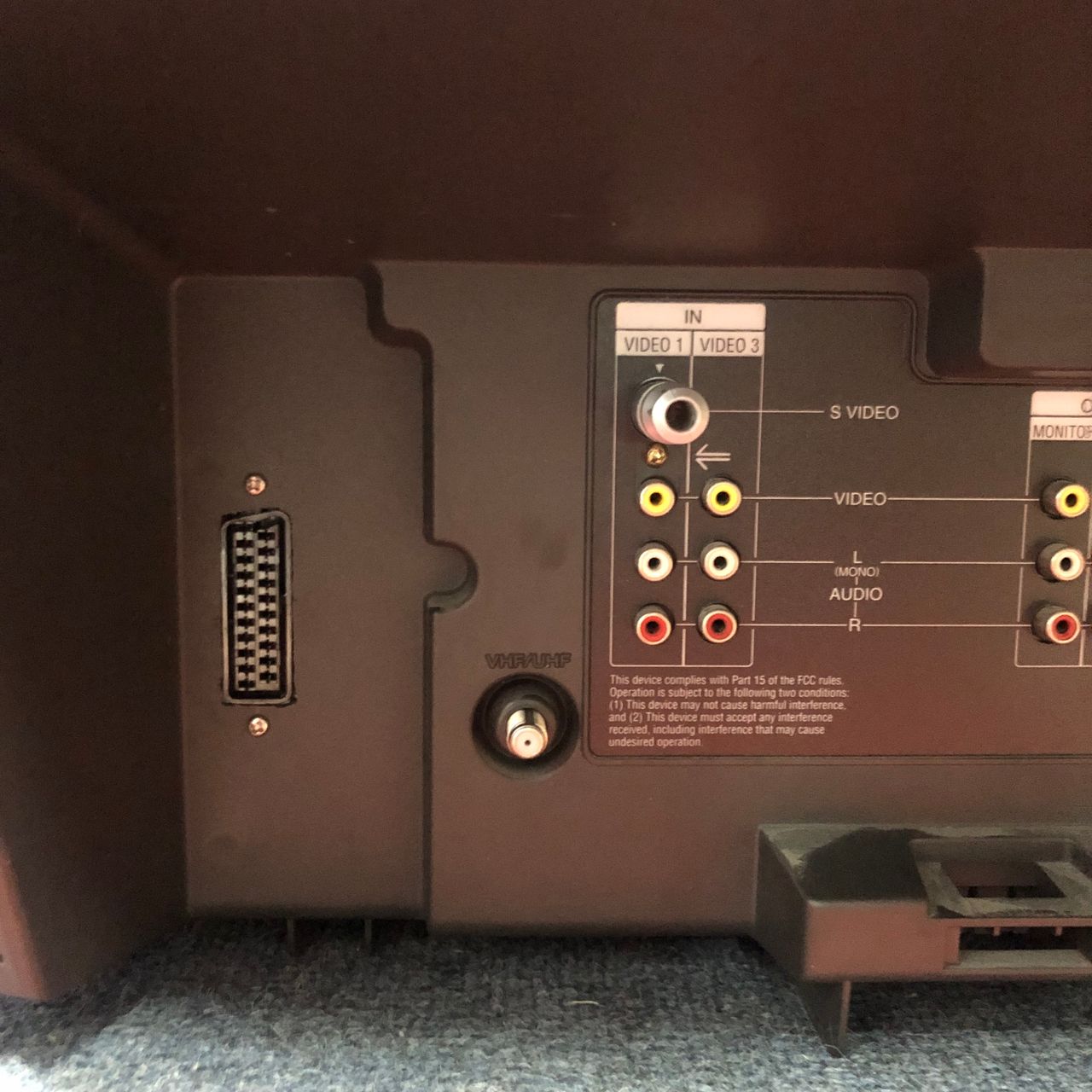
- Inputs: RF, Composite, S-Video
RGB mux diagram
Prepare the mux diagram. If you are building your own circuit, this diagram should help.
Performing the mod
STEP 1: Remove the following components
Remove
- R1123
- R1128
- R133
STEP 2: Add a diode to blanking (optional, but recommended)
Blanking diode added. Helps reduce interference. This mod was performed without shielded cables internally and absolutely no interference was noticed.
Below picture was taken from KV-27V20 ![]()
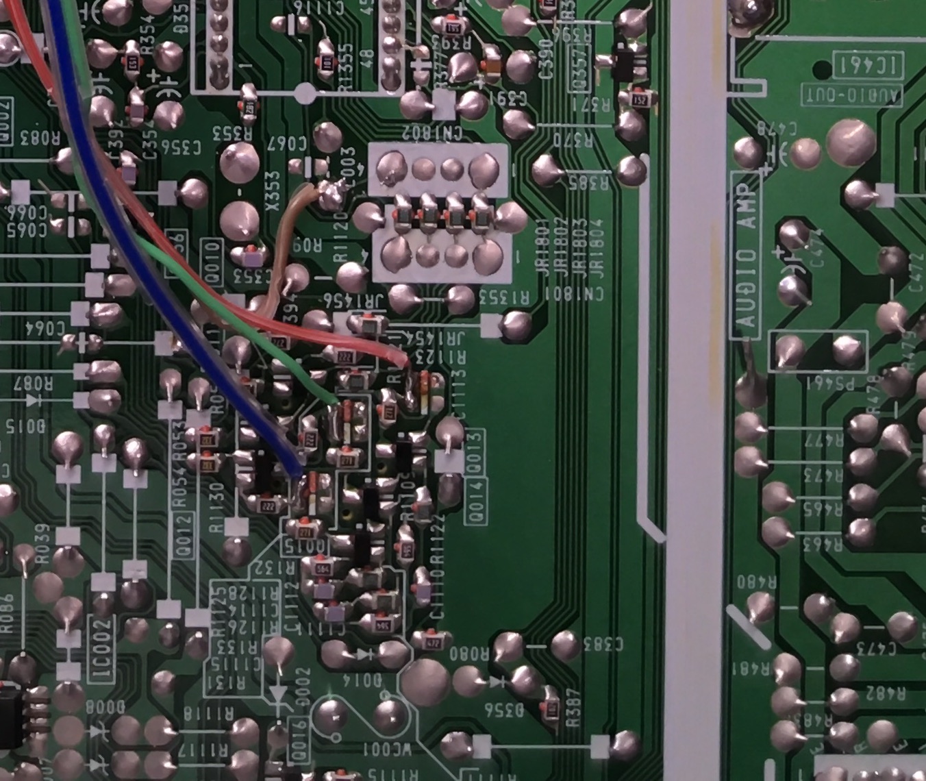
STEP 3: Connect RGB and blanking wires
Refer to the picture below for the correct soldering points for the R, G, B, and blanking wires. When soldering the R, G, and B wires, ensure you don't solder to the pad that is connected to the ground.
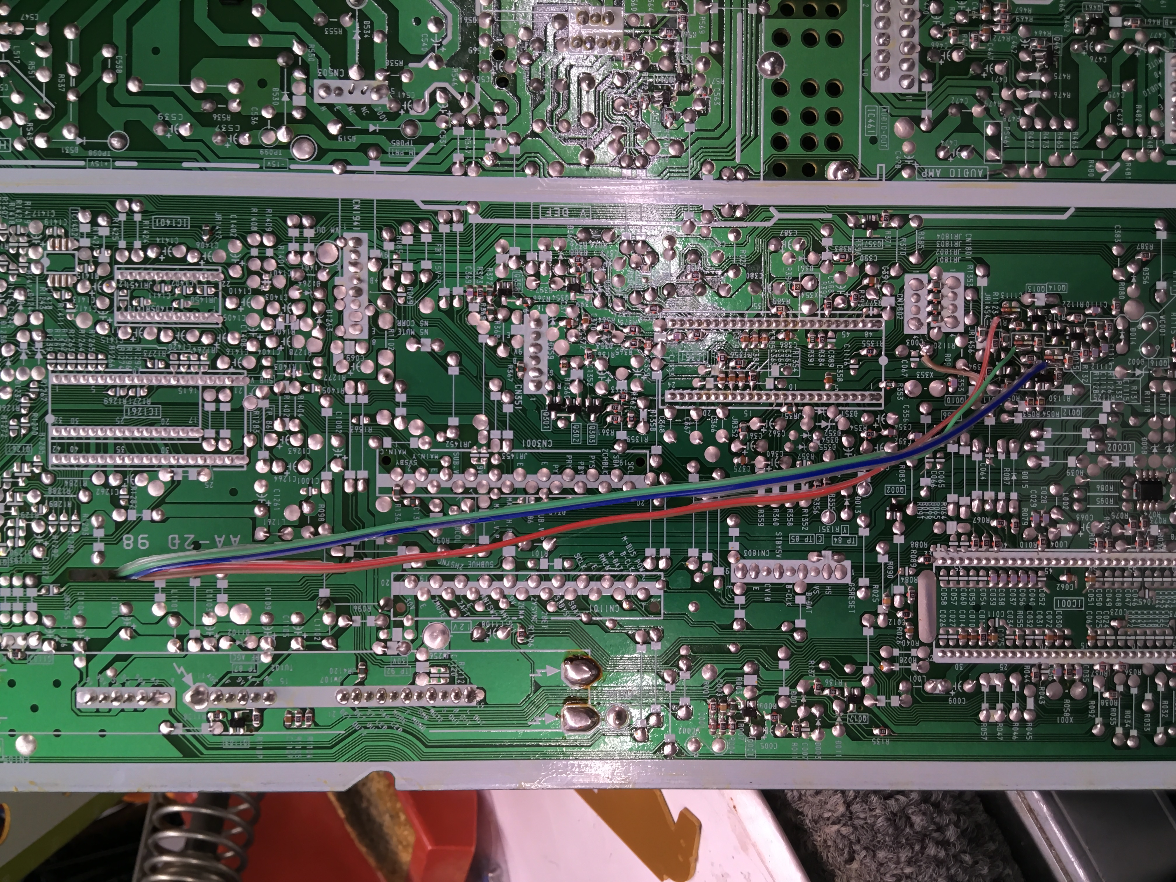
STEP 4: Connect audio, ground and sync wires
Now, it's time to turn our attention to the U board. In the image below, you can see where the audio, ground, and sync wires are connected.
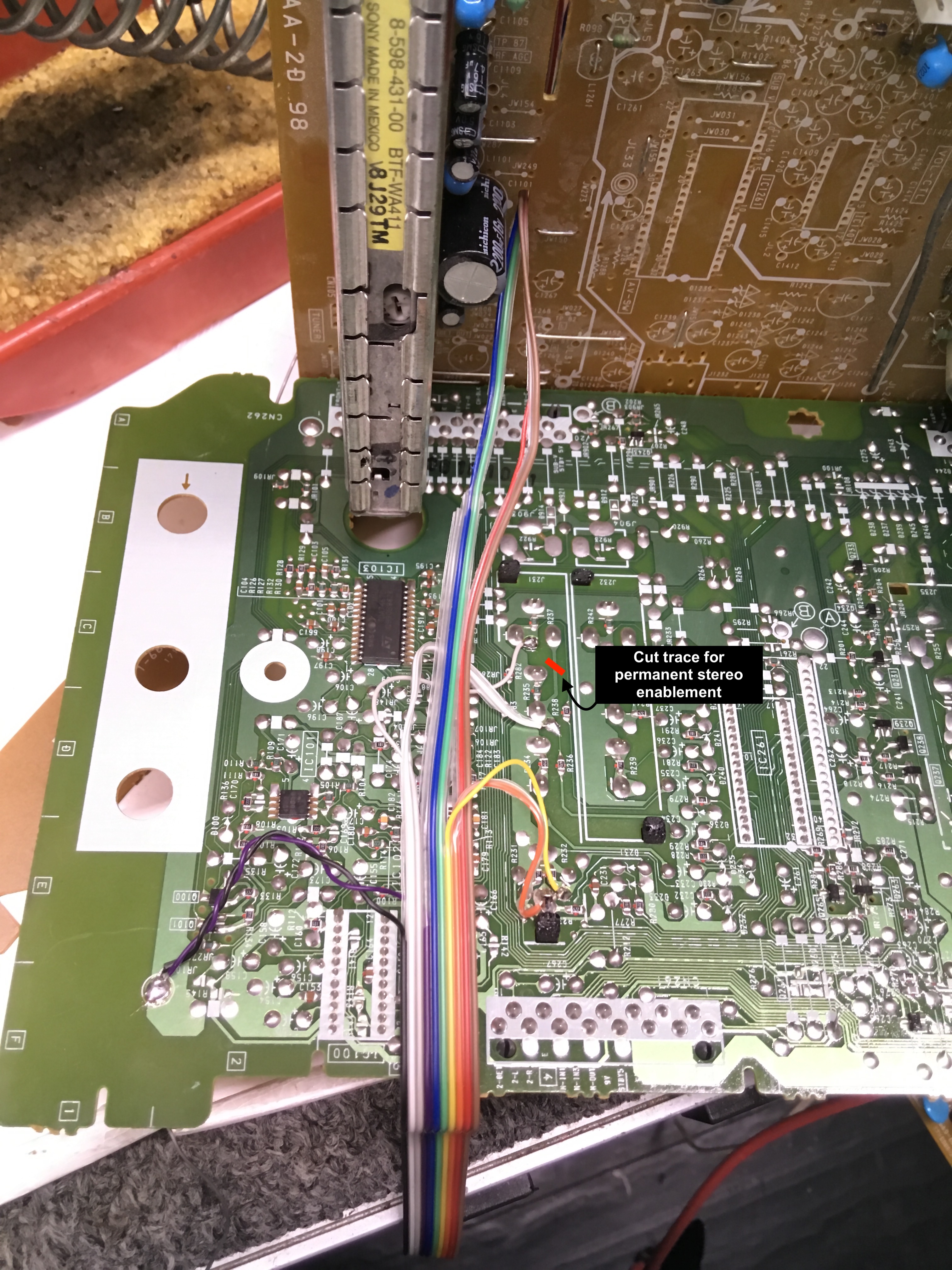
- Red wire is audio right = grey wire on ribbon cable
- White wire is audio left = white wire on ribbon cable
- Black = black (common ground)
- Yellow = yellow (sync using luma input)
To enable the luma input, I chose to use a dummy S-Video plug. Essentially, this means simply plugging an S-Video cable into the S-Video port without connecting it to anything else. You can get creative with this setup by adding a switch to toggle luma on and off, permanently enabling luma, or even using a transistor to activate luma automatically when a SCART cable is connected using the 5V blanking signal. However, I opted for a straightforward and reliable solution with the dummy plug. This approach allows me to seamlessly use both S-Video and Composite input from the back panel whenever needed.
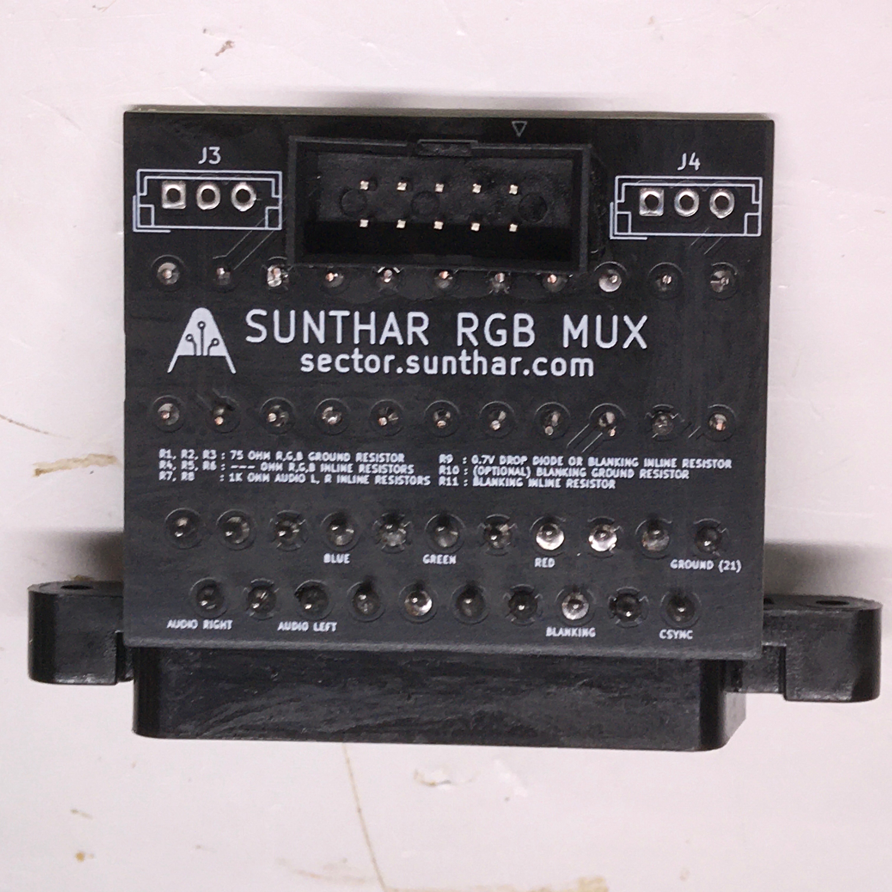
STEP 5: Build your mux circuit
This mod uses the RGB mux board. This is optional, but will make your mod easier and stable. You can also create the circuit presented in the schematics above without the board. Please also checkout the mux calculator to play with your own values.
| On Sony CRT Chassis | KV-32V40 |
|---|---|
| CRT RGB inline resistor | 2.2kΩ |
| CRT RGB ground resistors removed | 390Ω |
| 0.1μF caps replaced | No |
| Add diodes on chassis RGB lines? | No |
| Add blanking diode on chassis | Yes |
| RGB mux board | KV-32V40 |
|---|---|
| Mux board RGB termination (R1, R2, R3) | 75Ω |
| Mux board RGB inline resistors (R4, R5, R6) | 330Ω |
| Mux board Audio LR (R7, R8) | 1kΩ |
| Mux board blanking diode (R9) | 1N4148 |
| Mux board blanking ground resistor (R10) | 330Ω |
| Mux board blanking resistor (R11) | 470Ω |
| Mux board transistor base resistor (R12) | 1kΩ |
| Mux board transistor (Q1) | PN2222A |
Compatible mux boards:
It is important to note that the blanking ground resistor (R10) is necessary to prevent strange black backgrounds from appearing on the KV-27S22 OSD text.
Picture of RGB mux rev B board 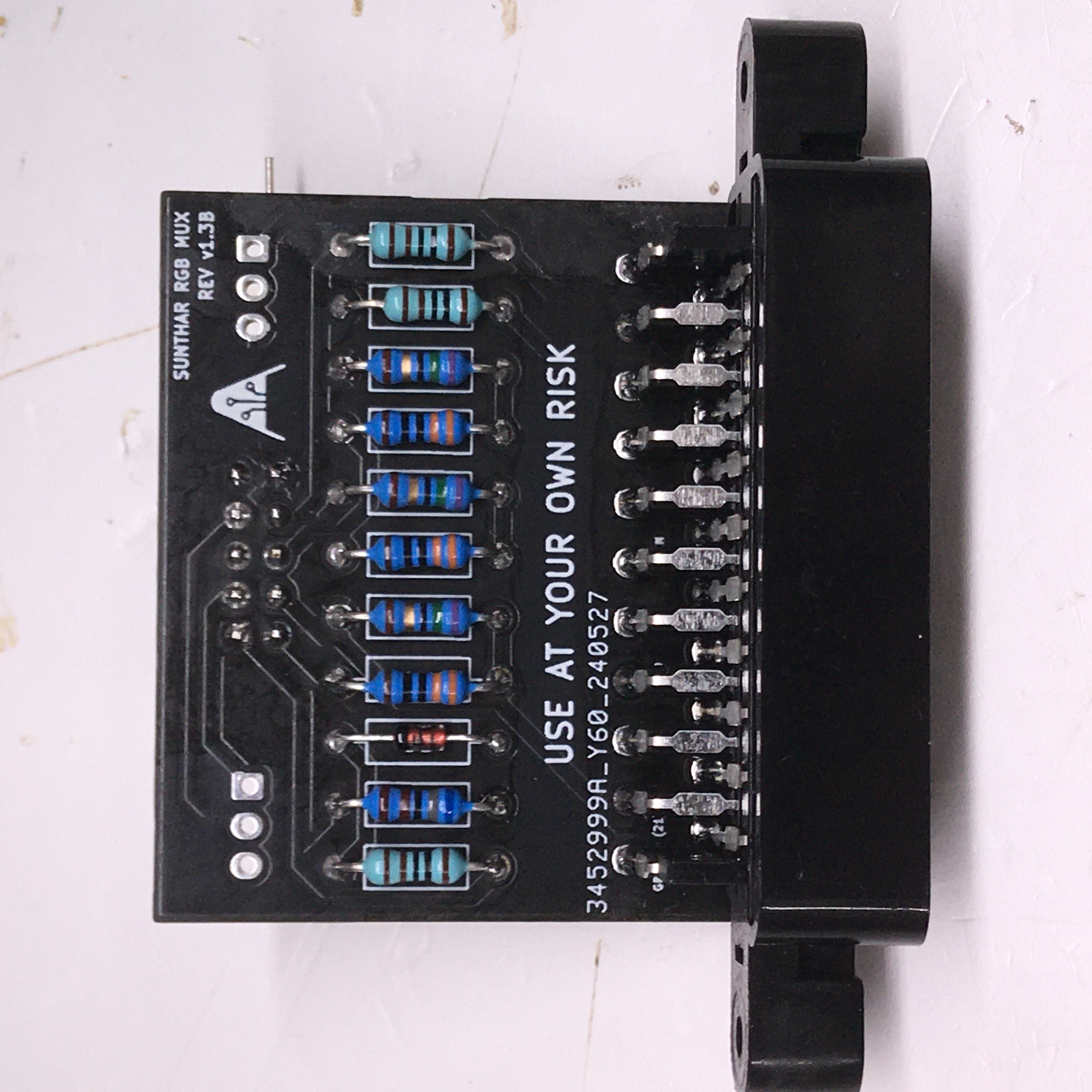
STEP 6: Attach the female SCART connector to TV
Creating a SCART cutout and mounting it is an art. I have a dedicated section for it. How to create and mount a SCART female plug?
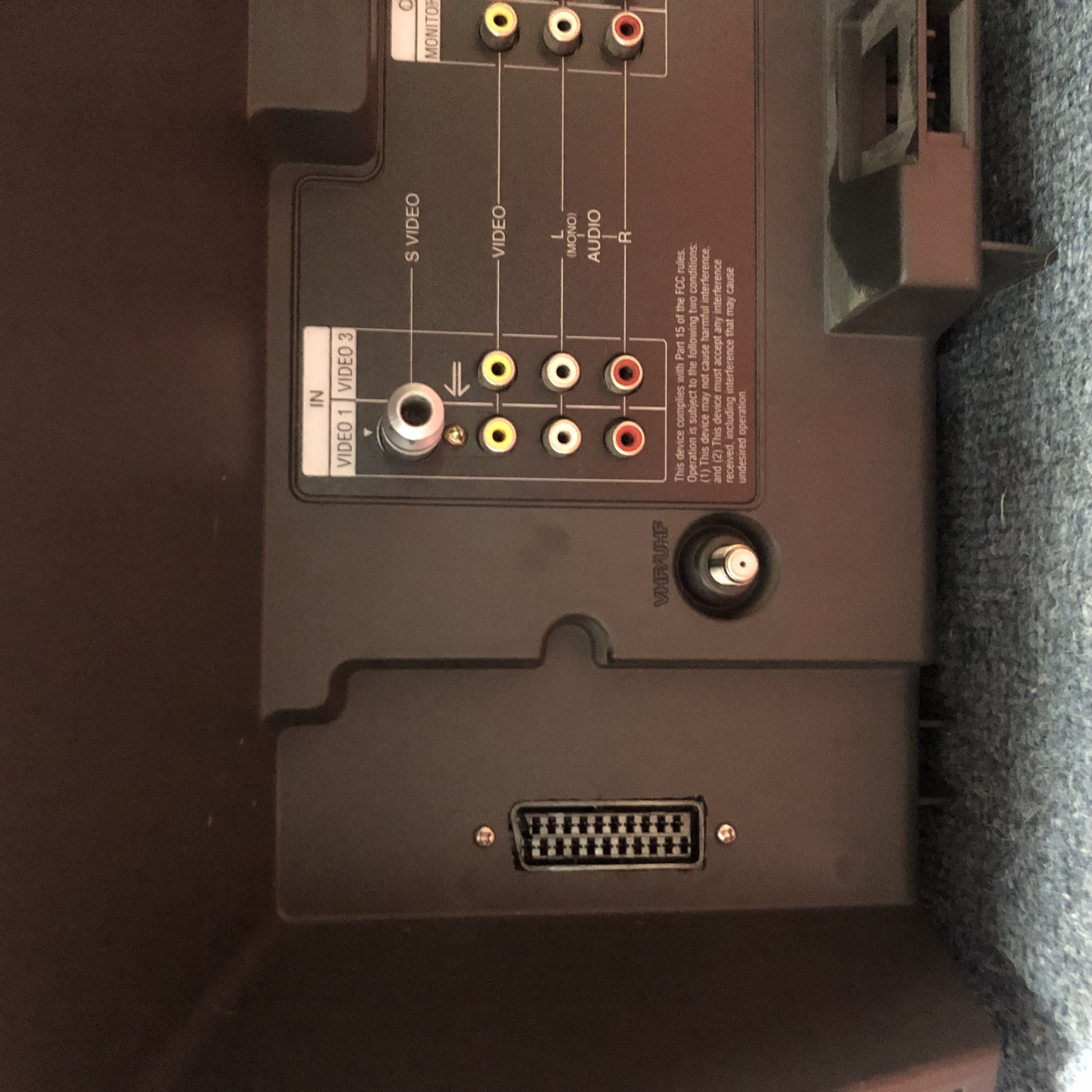
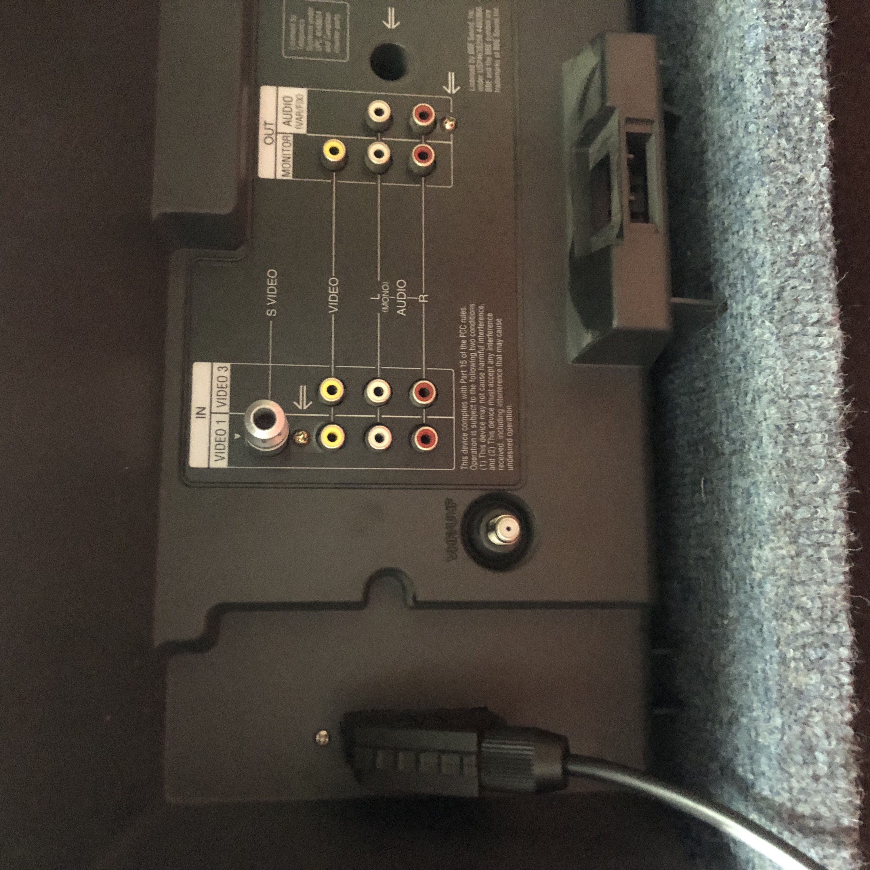
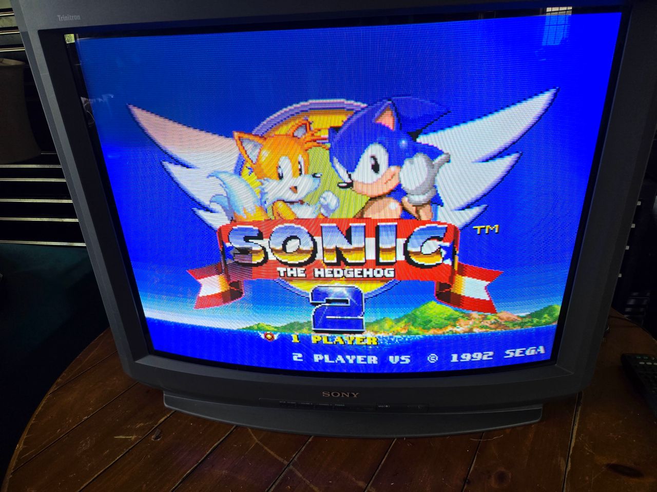
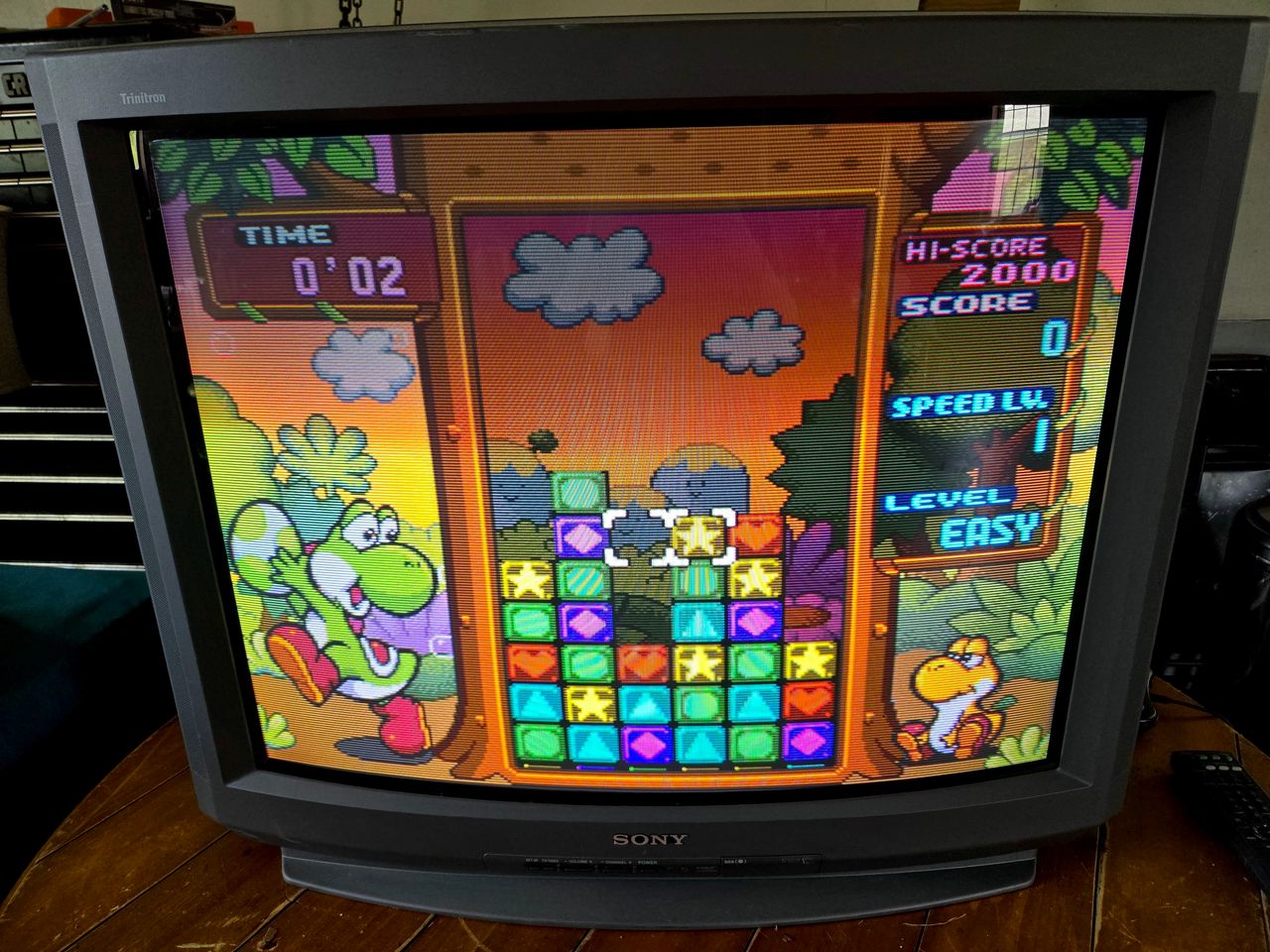
Pictures
Games & Pattern
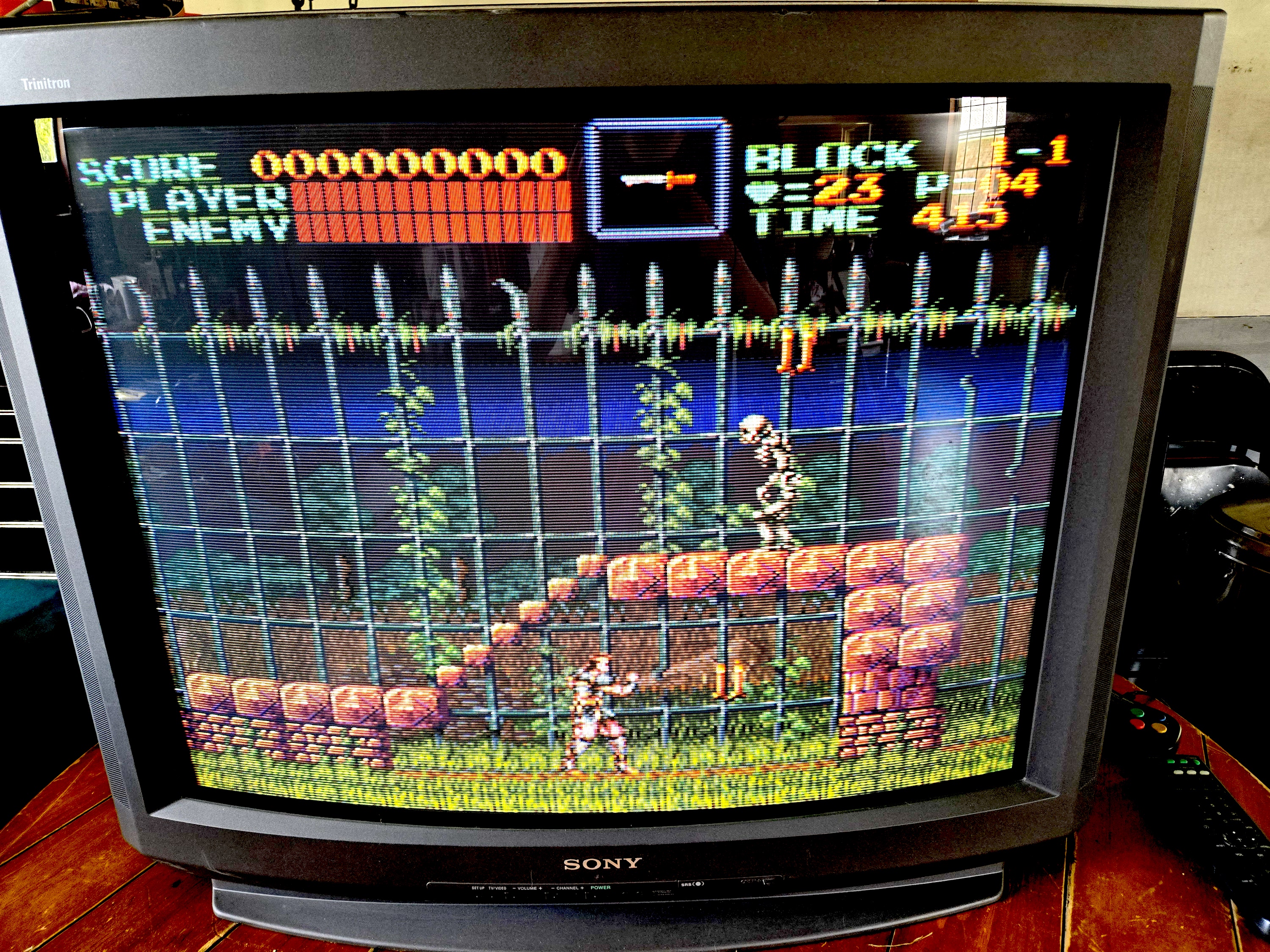
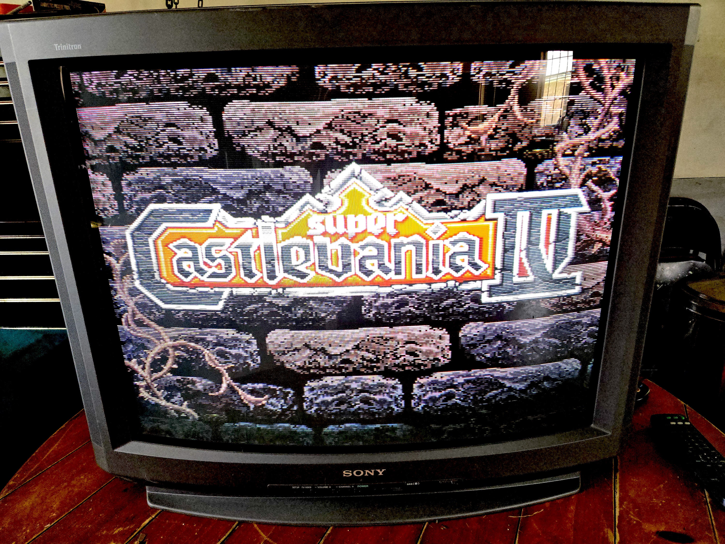
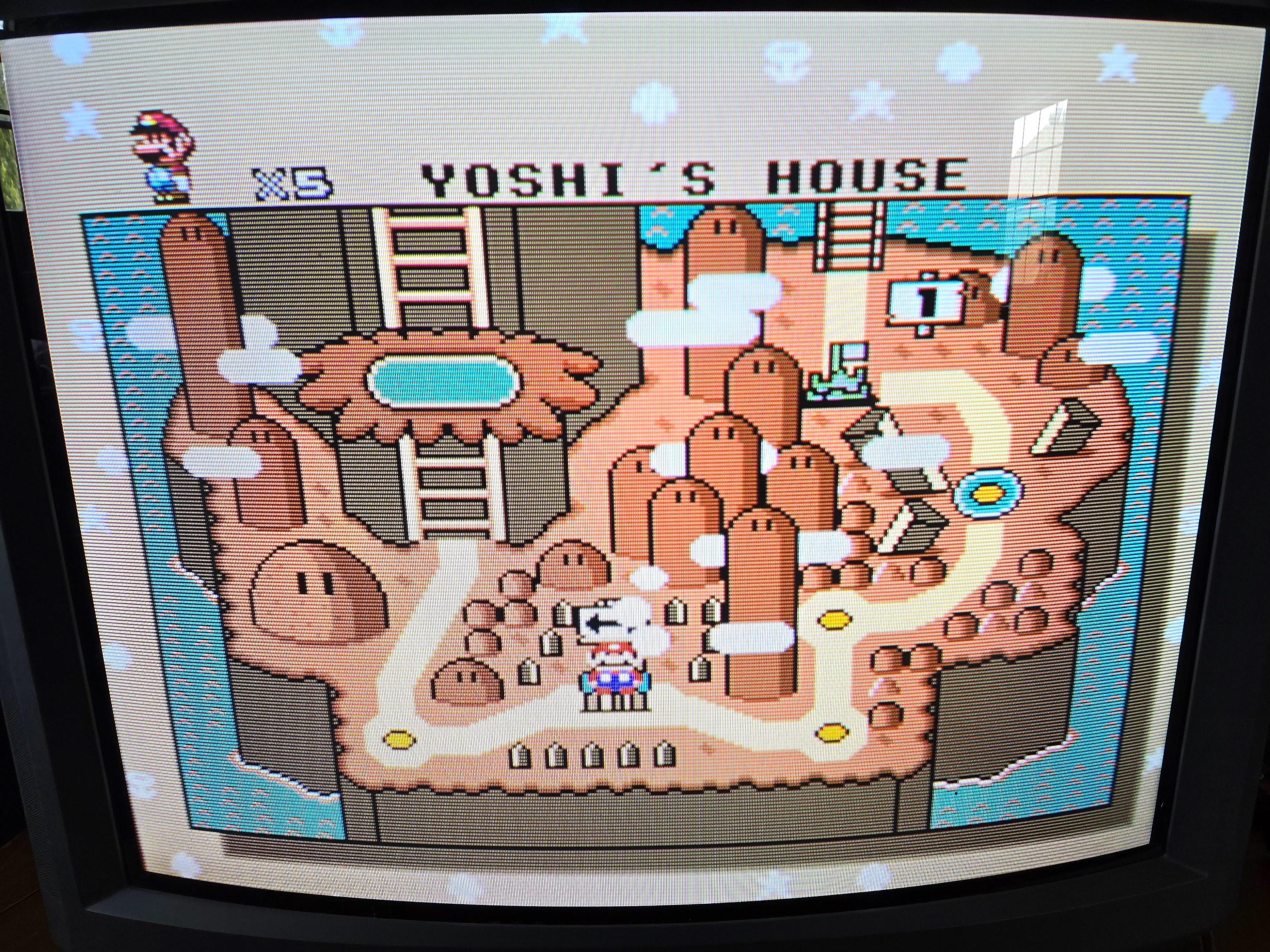
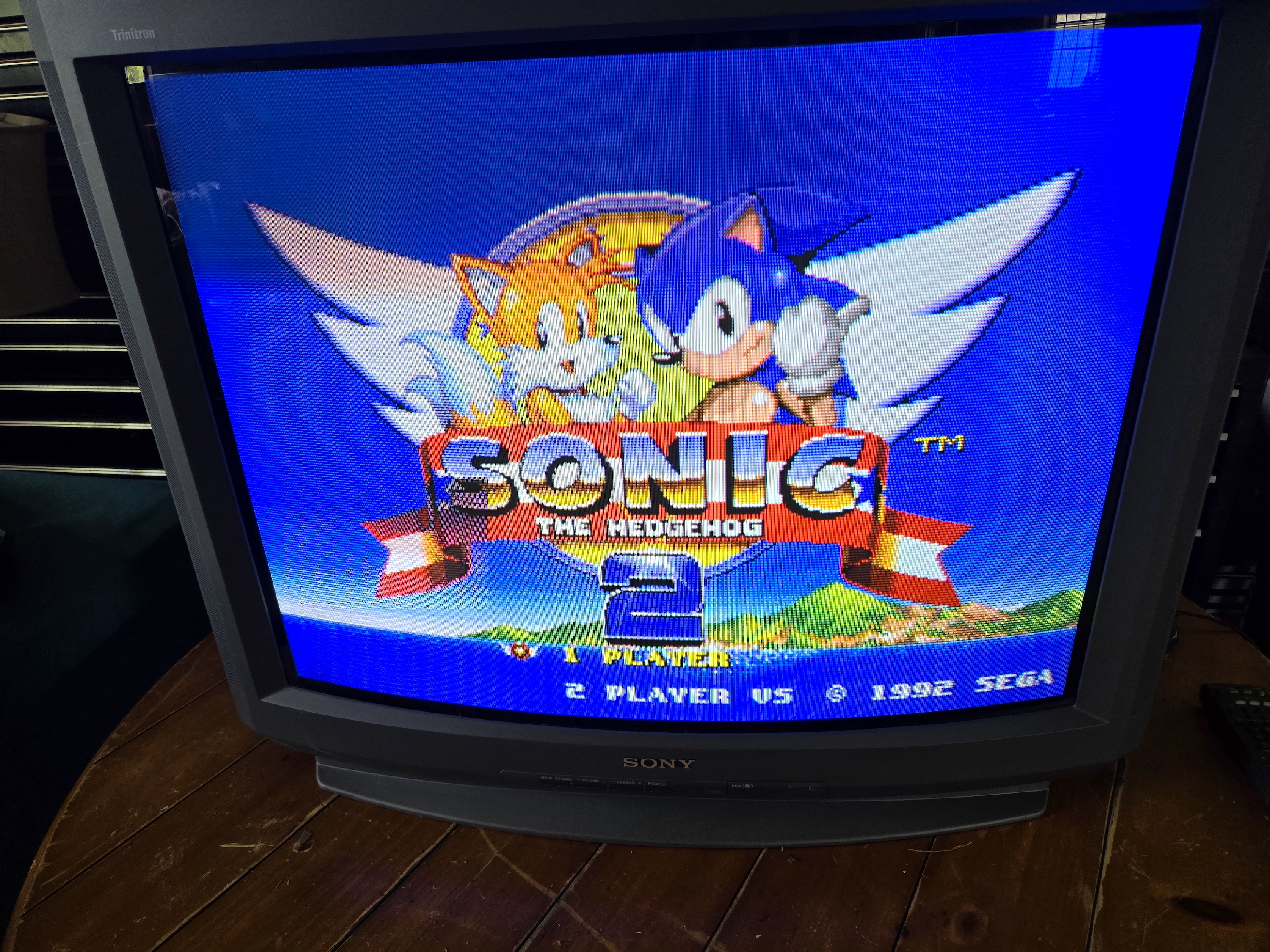
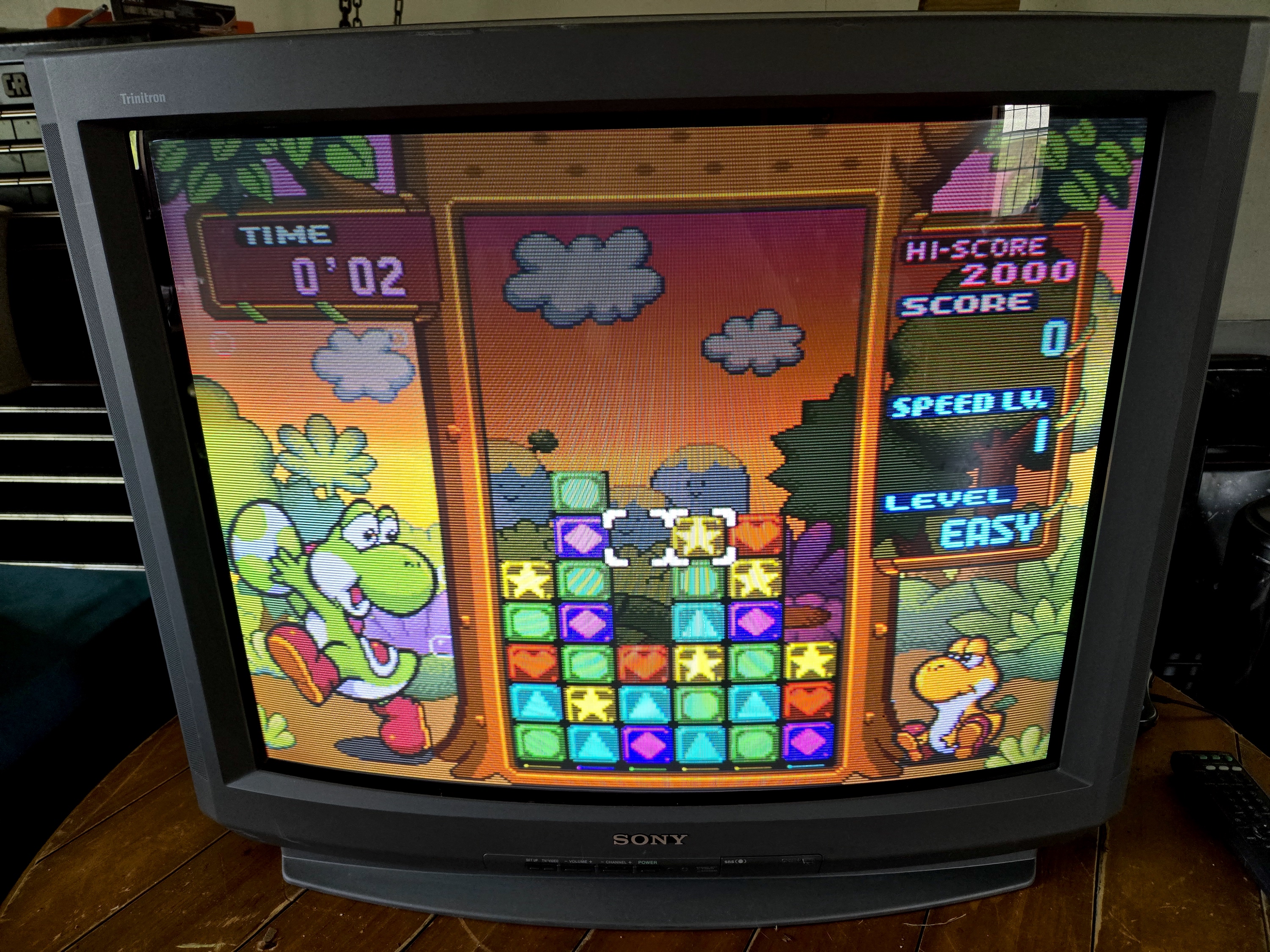
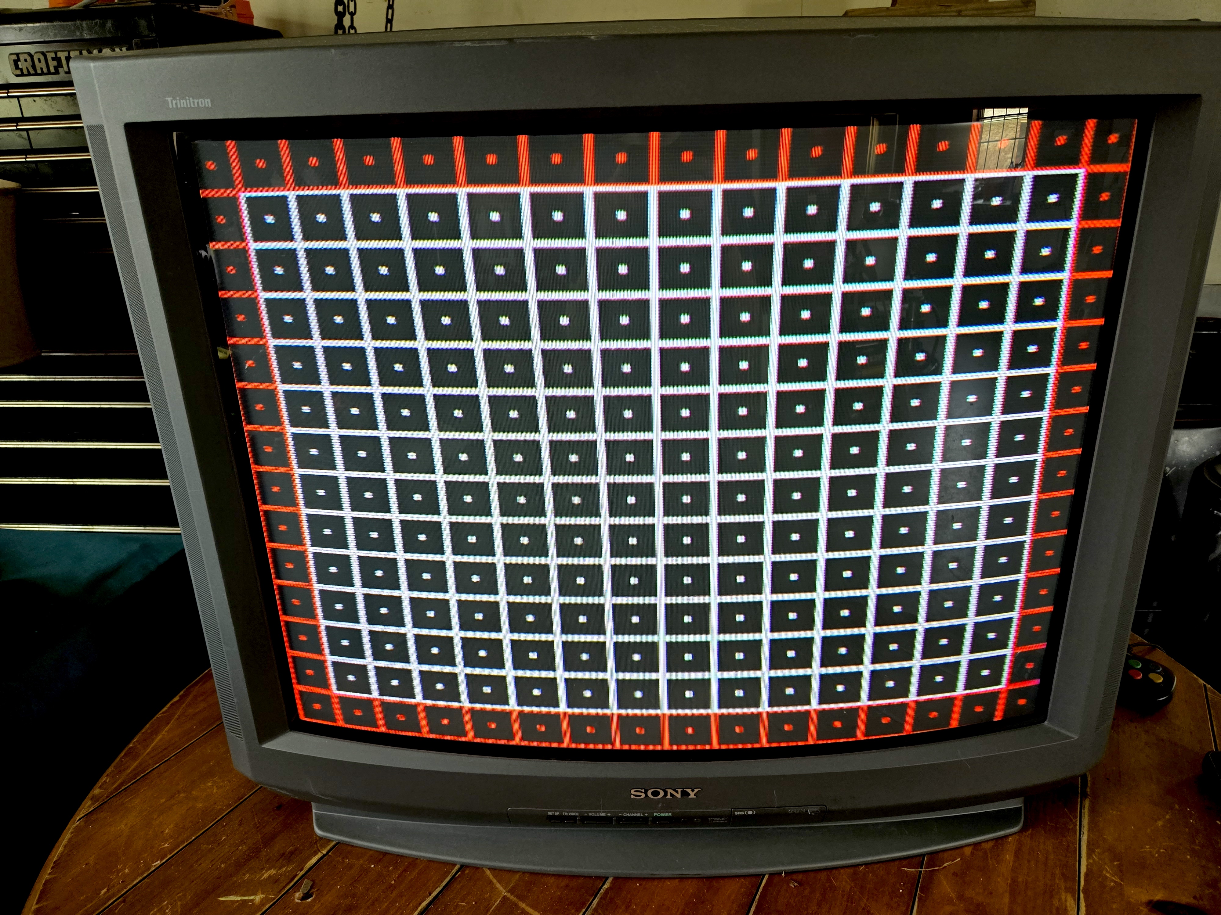
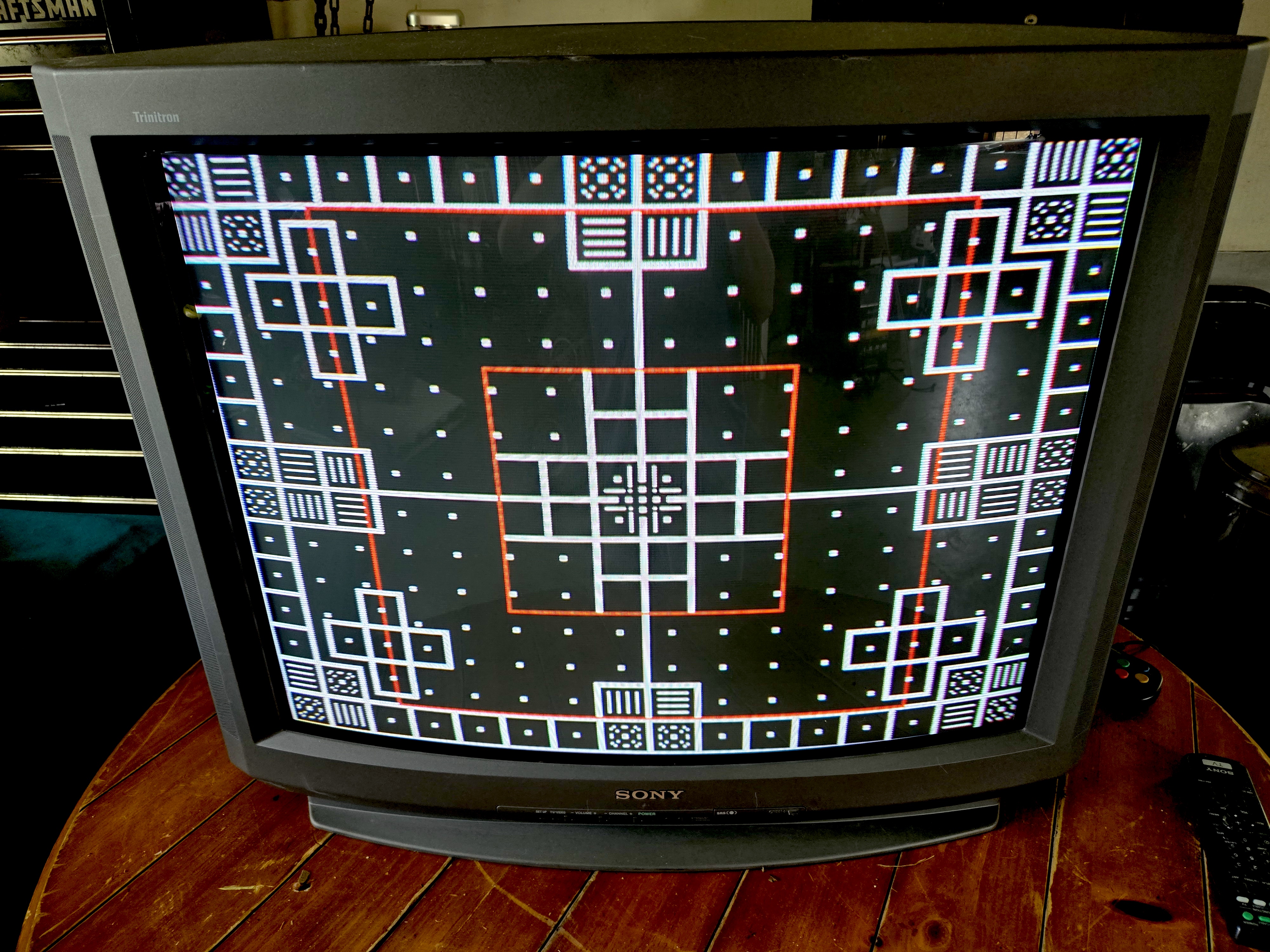
Pictures
Reference Photos