Sony (BA-4D) KV-27S42 RGB
Sony (BA-4D) KV-27S42 CRT RGB mod
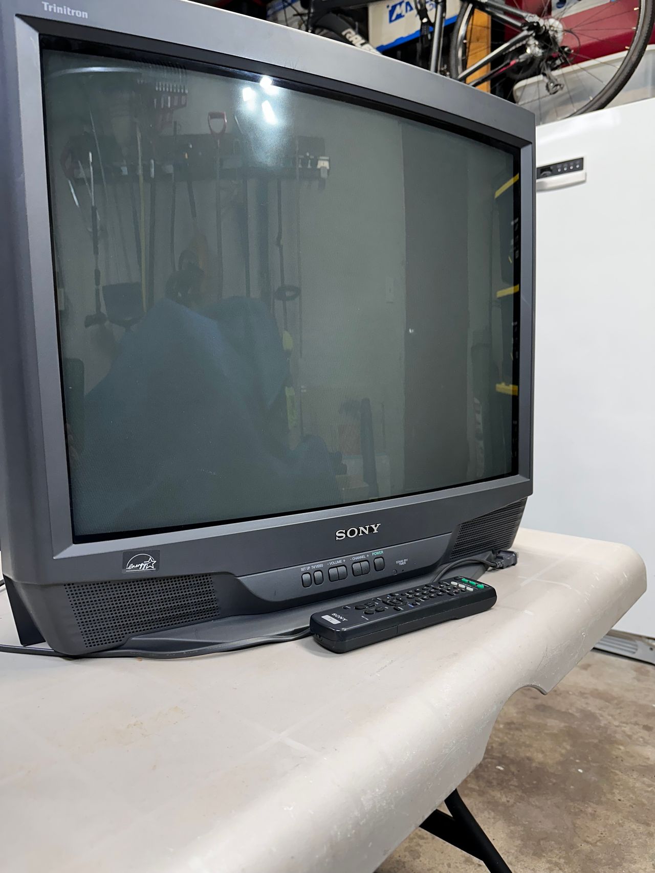
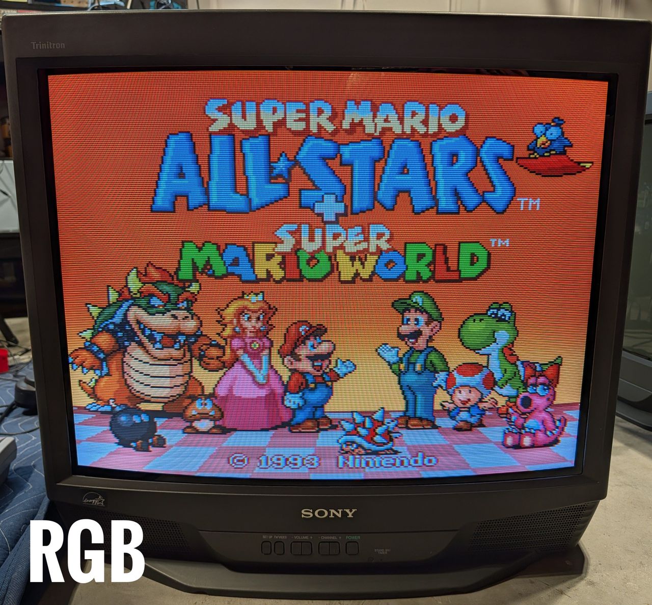
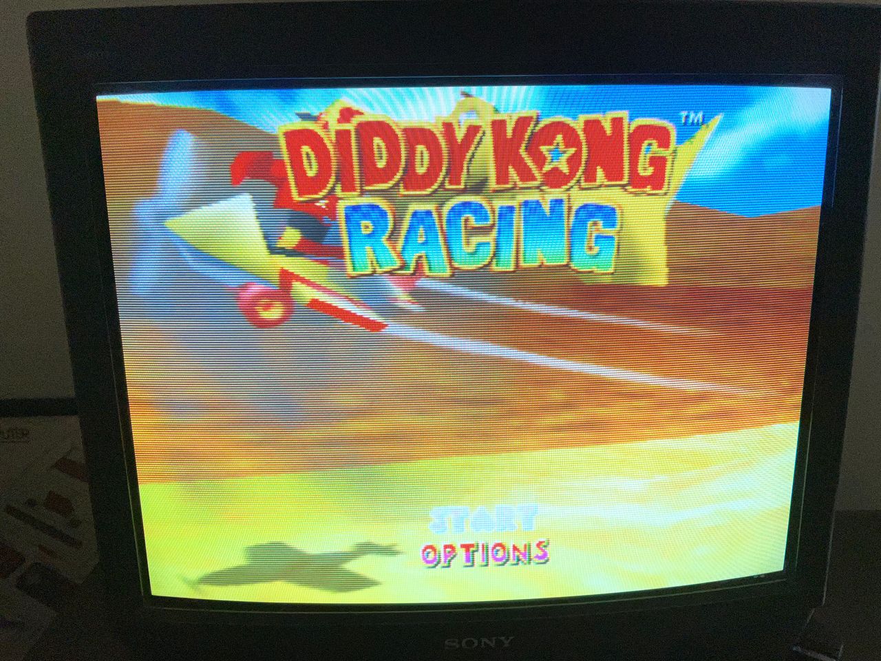
The Sony KV-27S42 is a retro 27" display, launched in 1999, known for its exceptional image quality and versatility. Featuring the acclaimed Sony Trinitron A68LML50X tube, this model offers a vibrant viewing experience with an aspect ratio of 4:3, making it ideal for classic gaming and retro content.
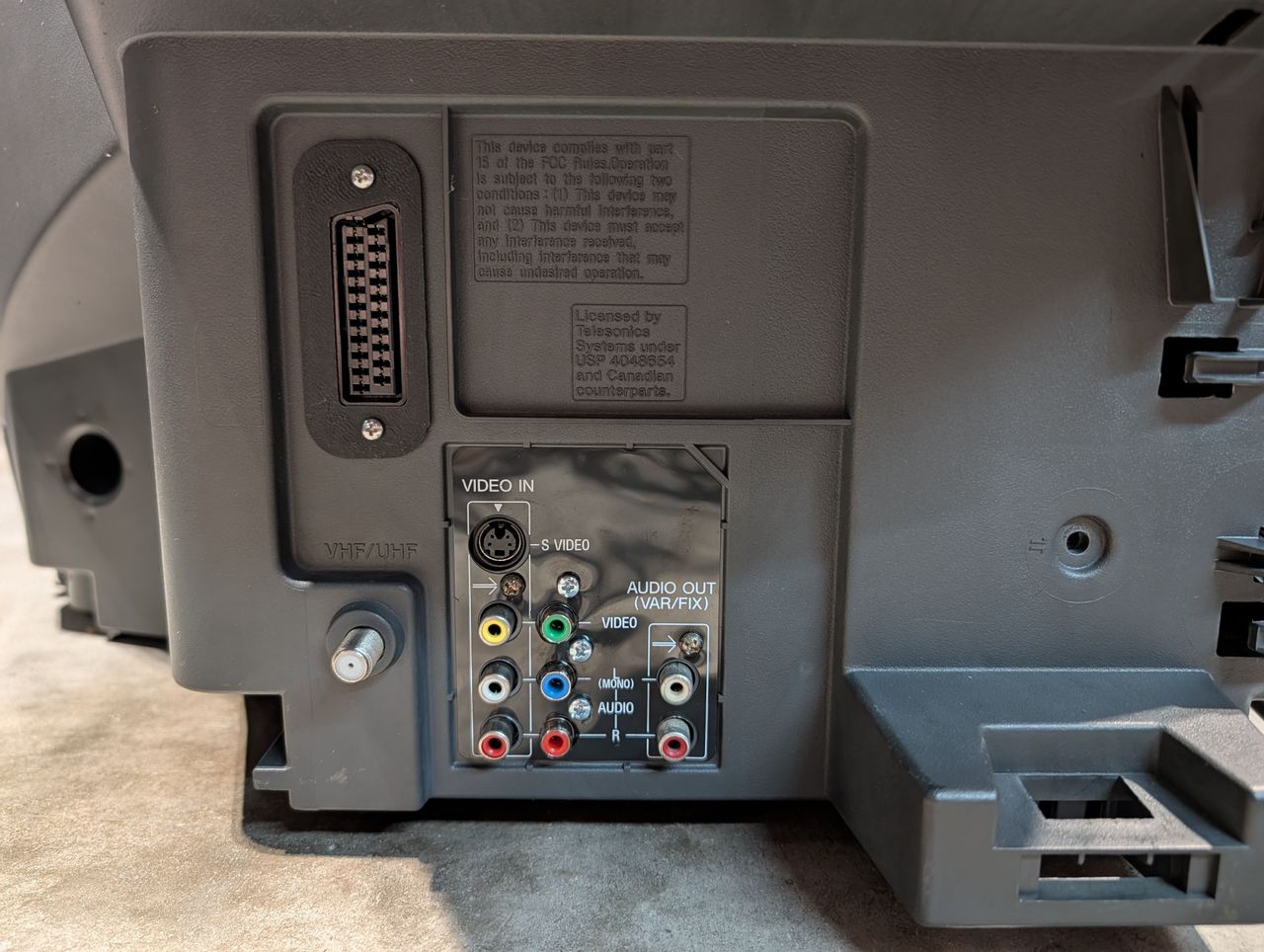
This CRT is equipped with multiple input options, including Composite, S-Video, and RF. For enthusiasts, the KV-27S42 is modifiable for RGB input using the recommended Sunthar mux board, enhancing its compatibility with several retro gaming consoles.
Sony KV-27S42 remains a sought-after model for those appreciating the nostalgia of CRT technology.
View full CRT details and more mod examples →
This advanced mod tutorial is divided into three chapters, focusing on advanced modifications to address previous challenges:
- Chapter 1: Addresses key challenges like requiring a dummy plug for stereo audio and a dummy S-Video plug to activate S-Video by grounding the detect pin.
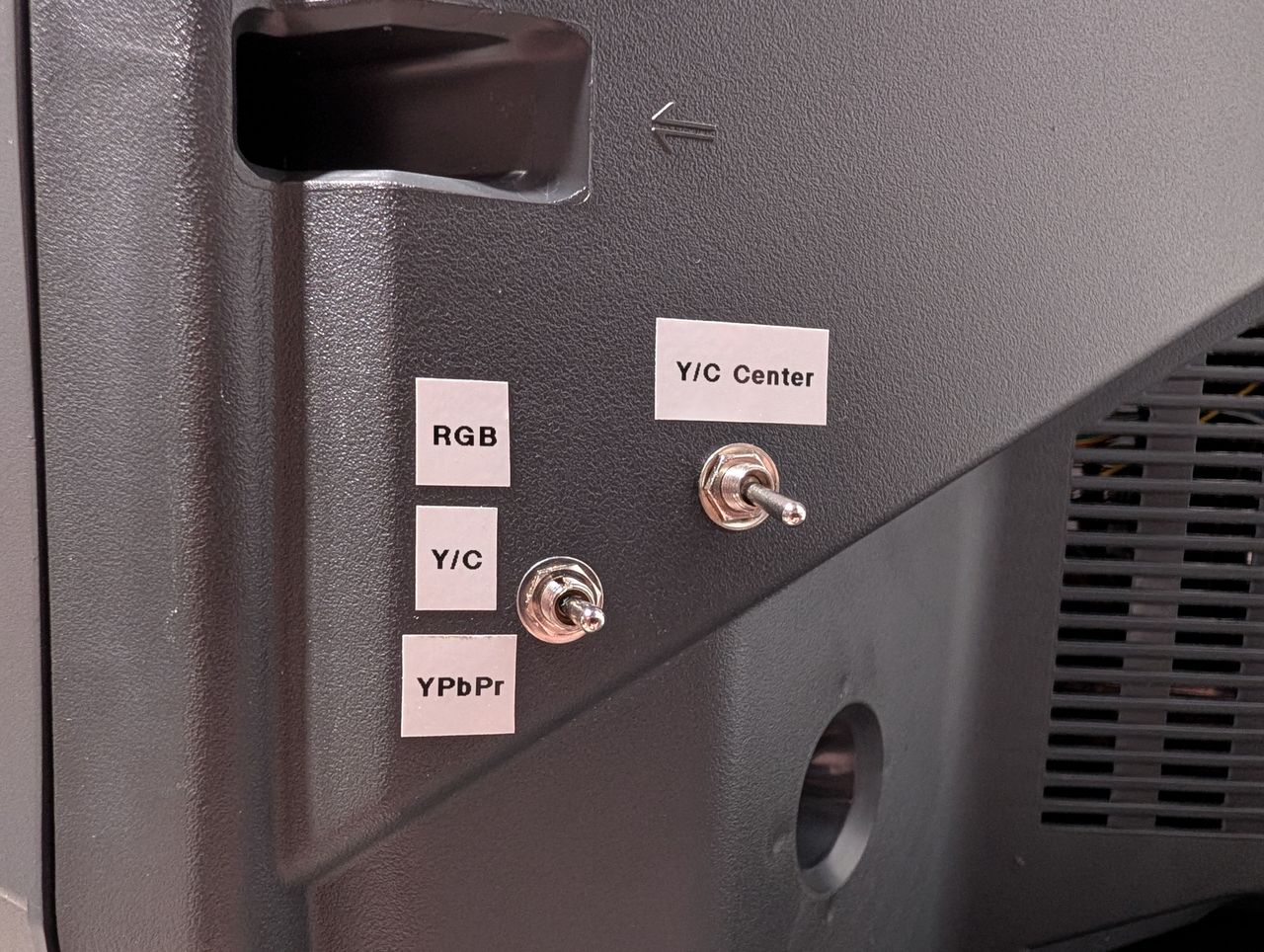
- Chapter 2: Explores how to use a remote control to seamlessly switch between RGB, composite, and component inputs.
- Chapter 3: Demonstrates how to utilize an external blanking signal, including lower-voltage signals from MiSTer, to switch inputs automatically. This allows all stock inputs to remain functional without requiring physical switches.
Chapter 2 & 3 is in progress.
Table of Contents
Contributors
Thank you to everyone who contributed to this guide:
- Aaron’s Retro Basement — showcase author
- Nostalgia FX Workshop — showcase author
- ALttN — showcase author
CRT safety
Caution
You can die doing this! So read carefully! CRT TV is not a toy. Do not open a CRT TV. If you don't have any prior knowledge about handling high voltage devices, this guide is not for you. CRT TV contains high enough voltage (20,000+ V) and current to be deadly, even when it is turned off.
Plan of attack
Manuals and Datasheets
- Sony KV-27S42 Service Manual
- KV-27S42_SM
- KV-27S42_UM
- Mitsubishi M37273MF-255SP Datasheet (OSD) — Available for Pro Users only. See CRT details for access.
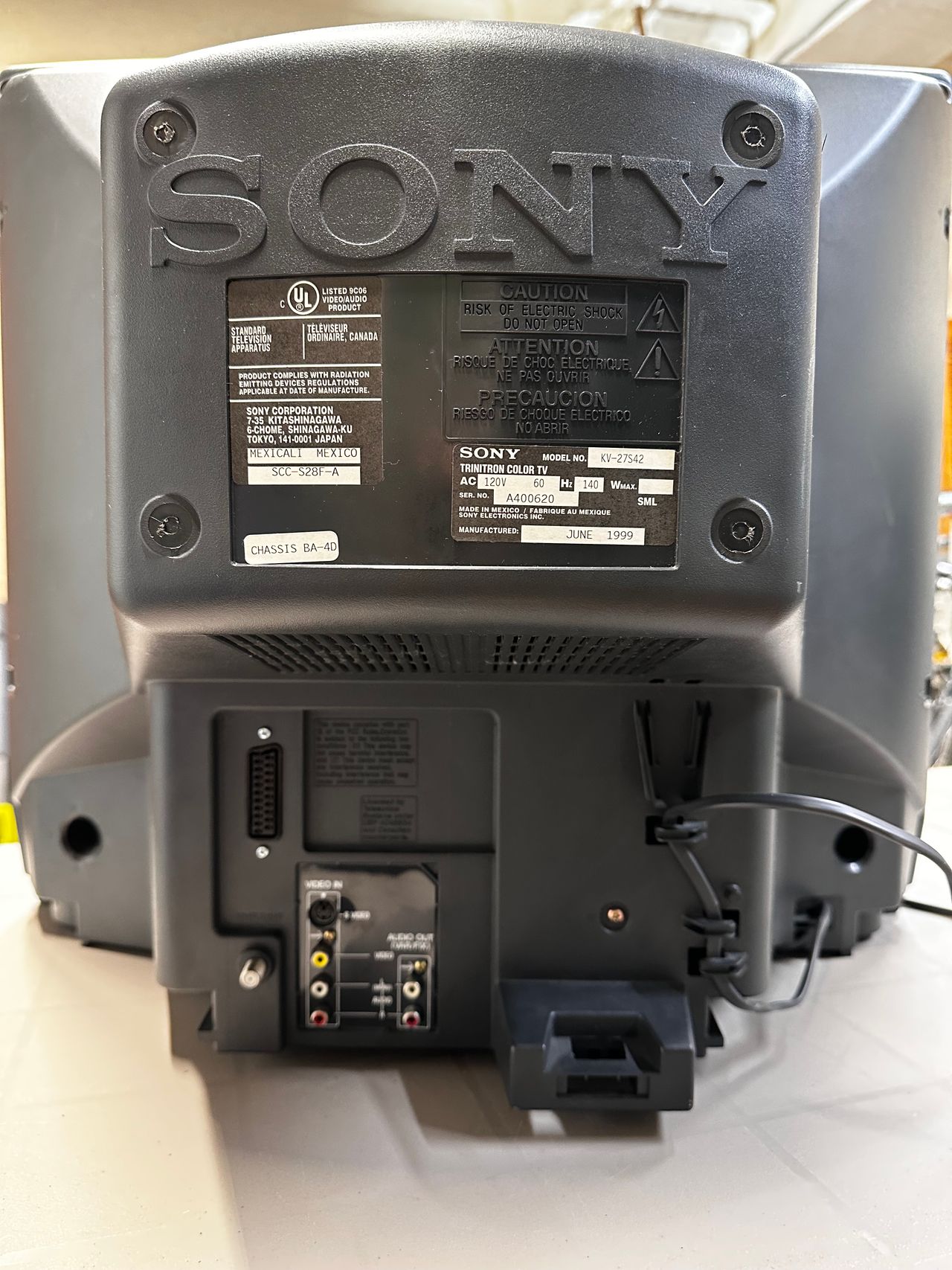
Specs
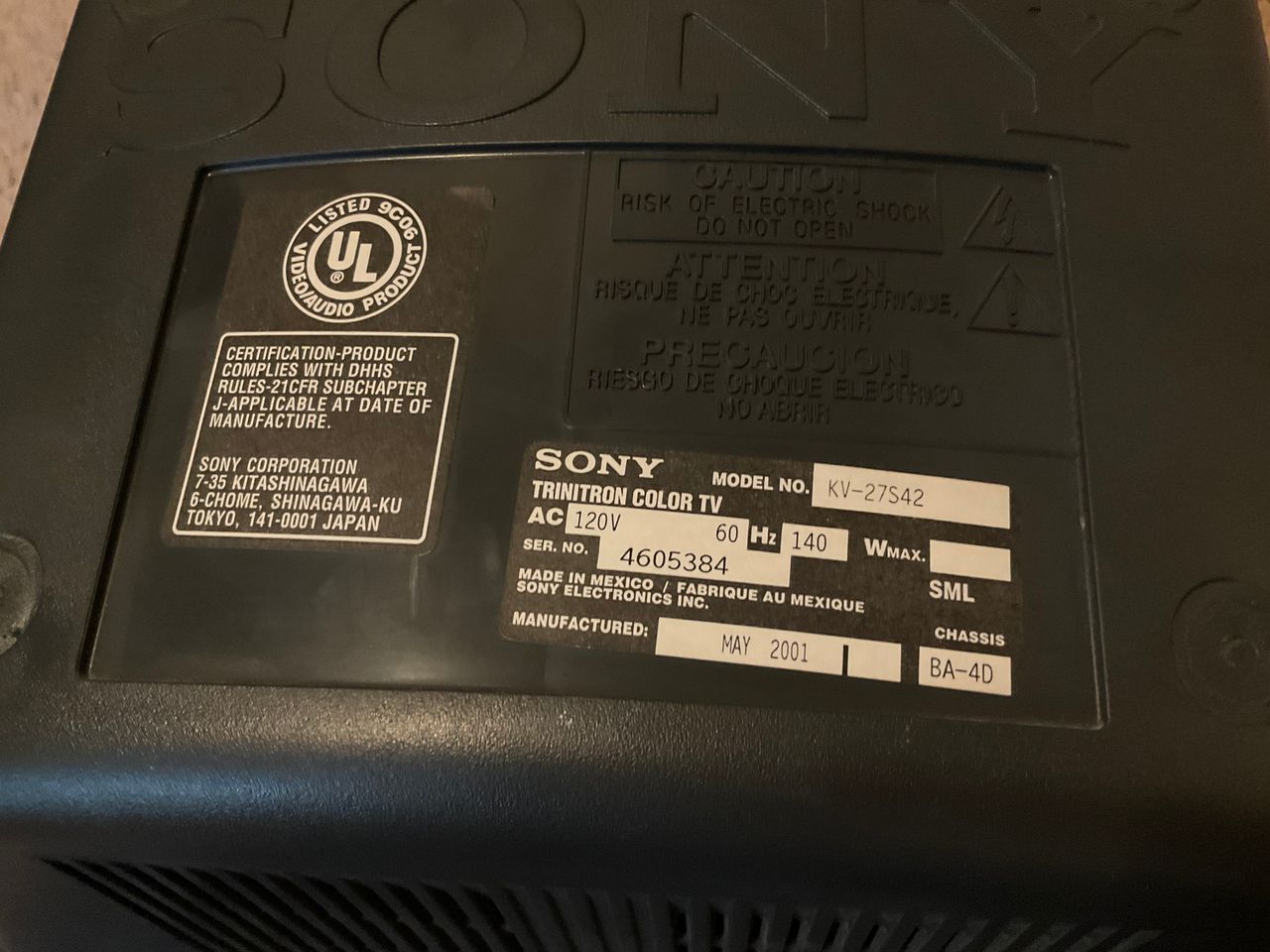
- Manufactured: Mexico (1999)
- Format: NTSC
- Chassis: BA-4D
- Tube: Sony Trinitron A68LML50X
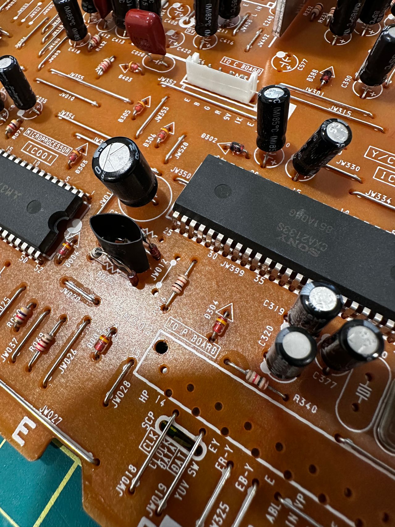
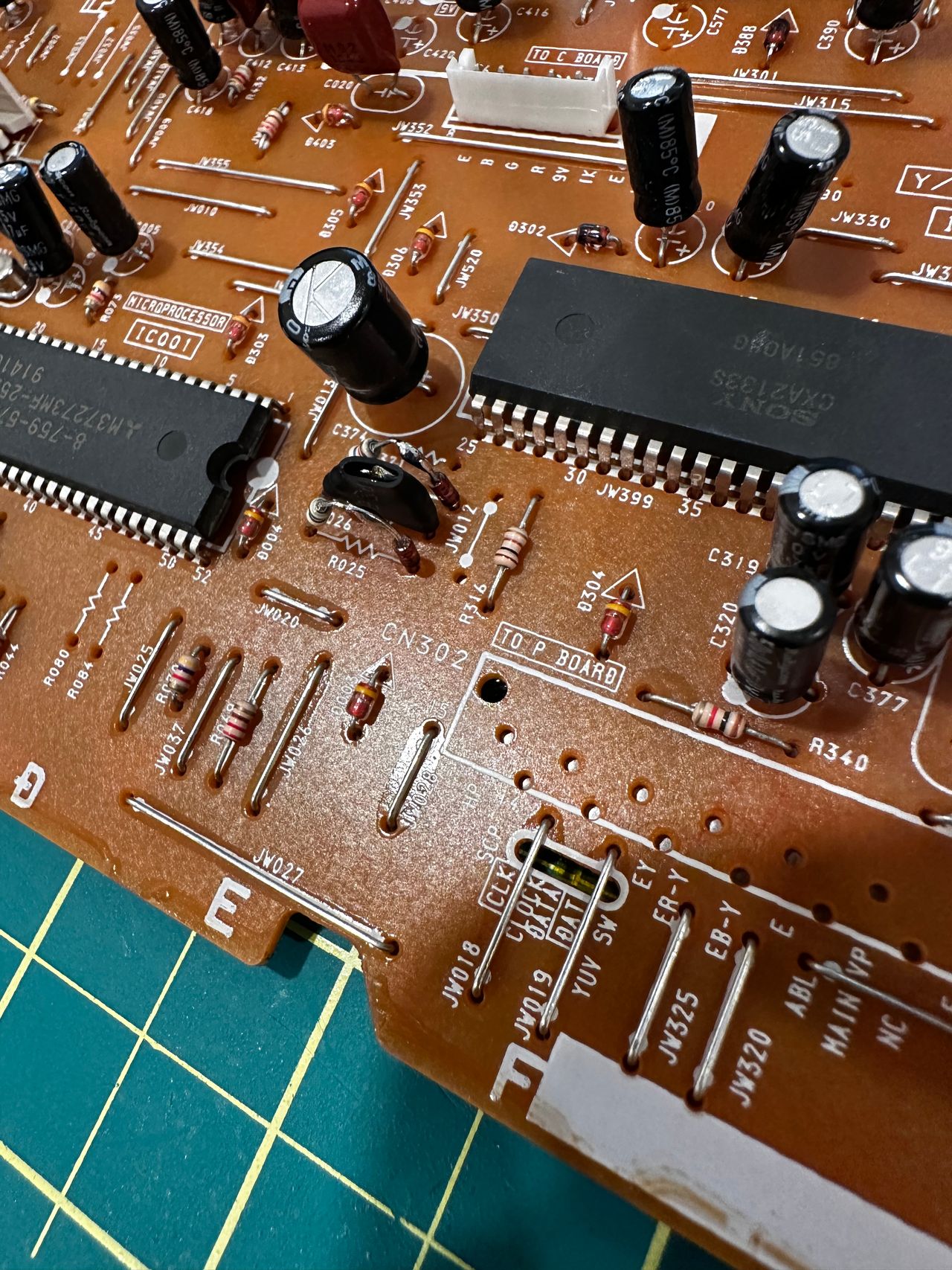
- Jungle Chip: Sony CXA2133AS
- OSD Chip: Mitsubishi M37273MF-255SP
- Screen Size: 27"
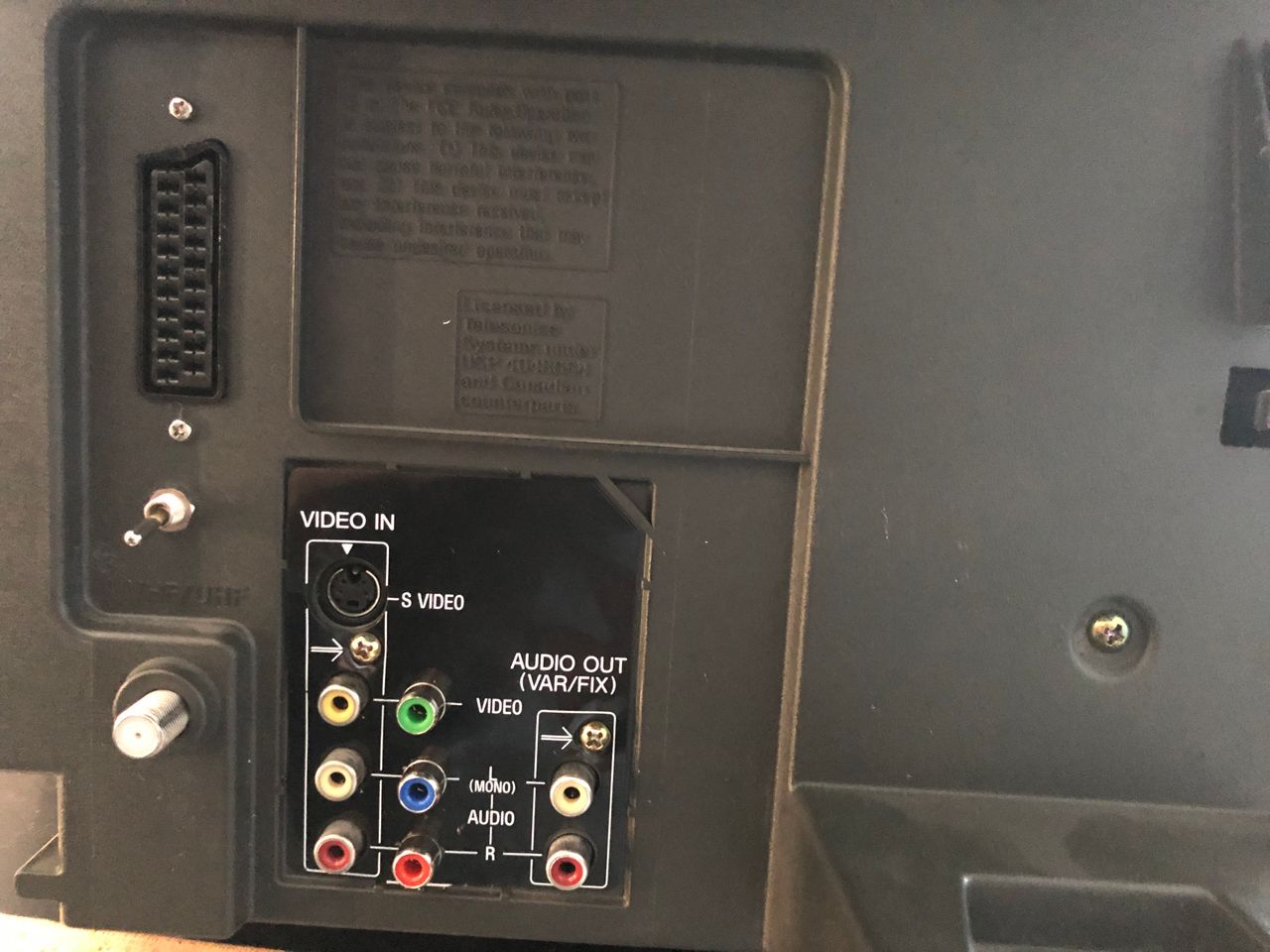
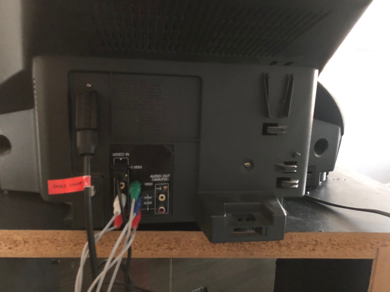
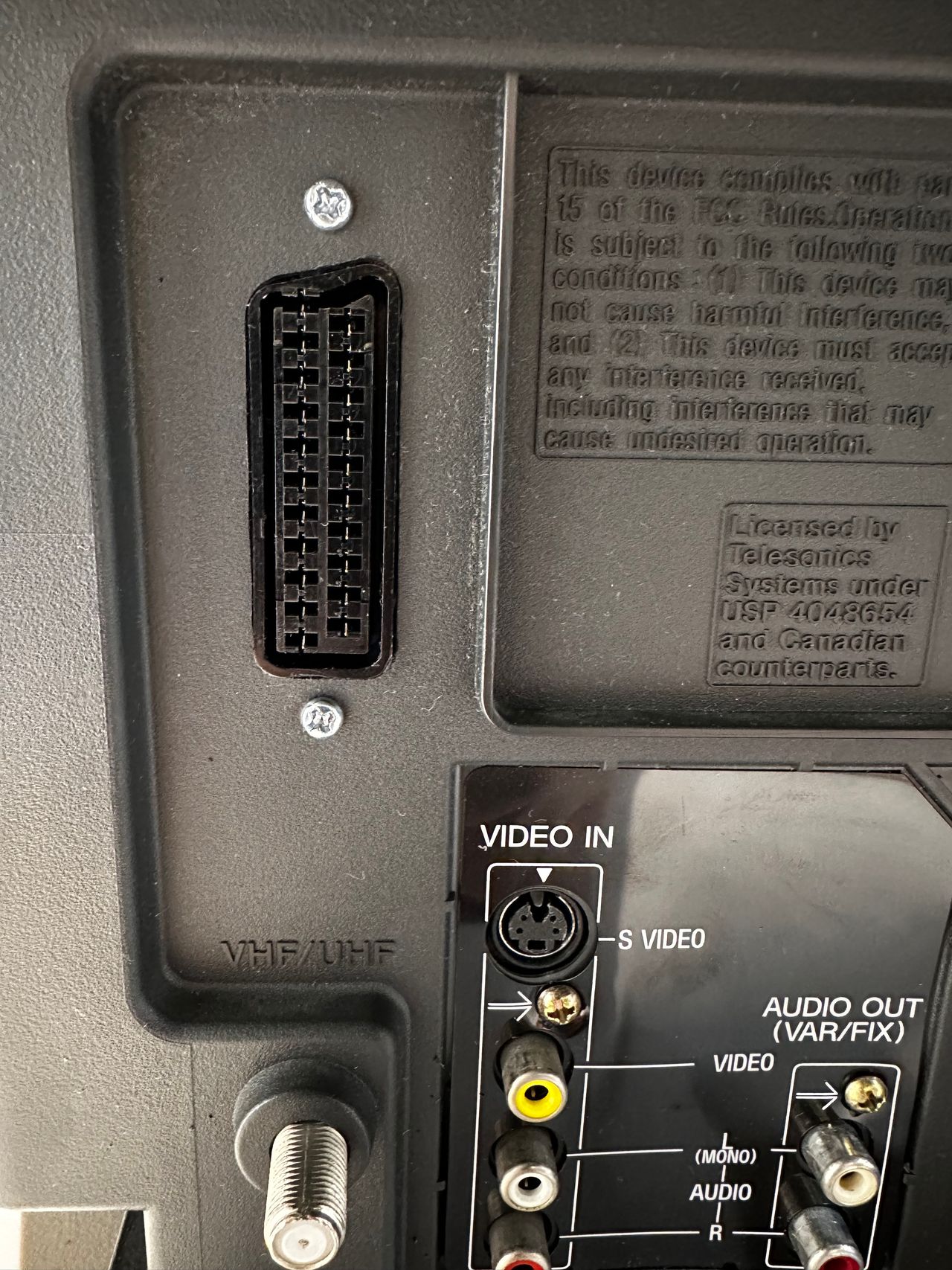
- Inputs: Composite, S-Video, RF
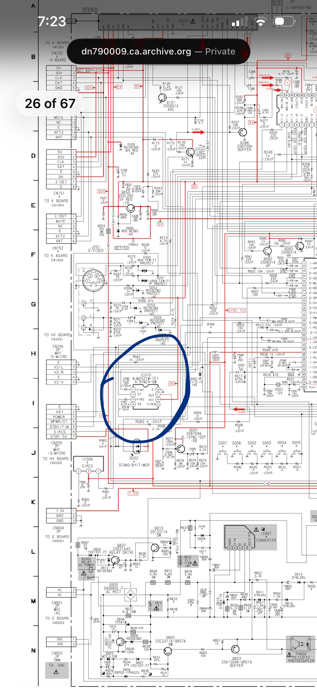
Schematics
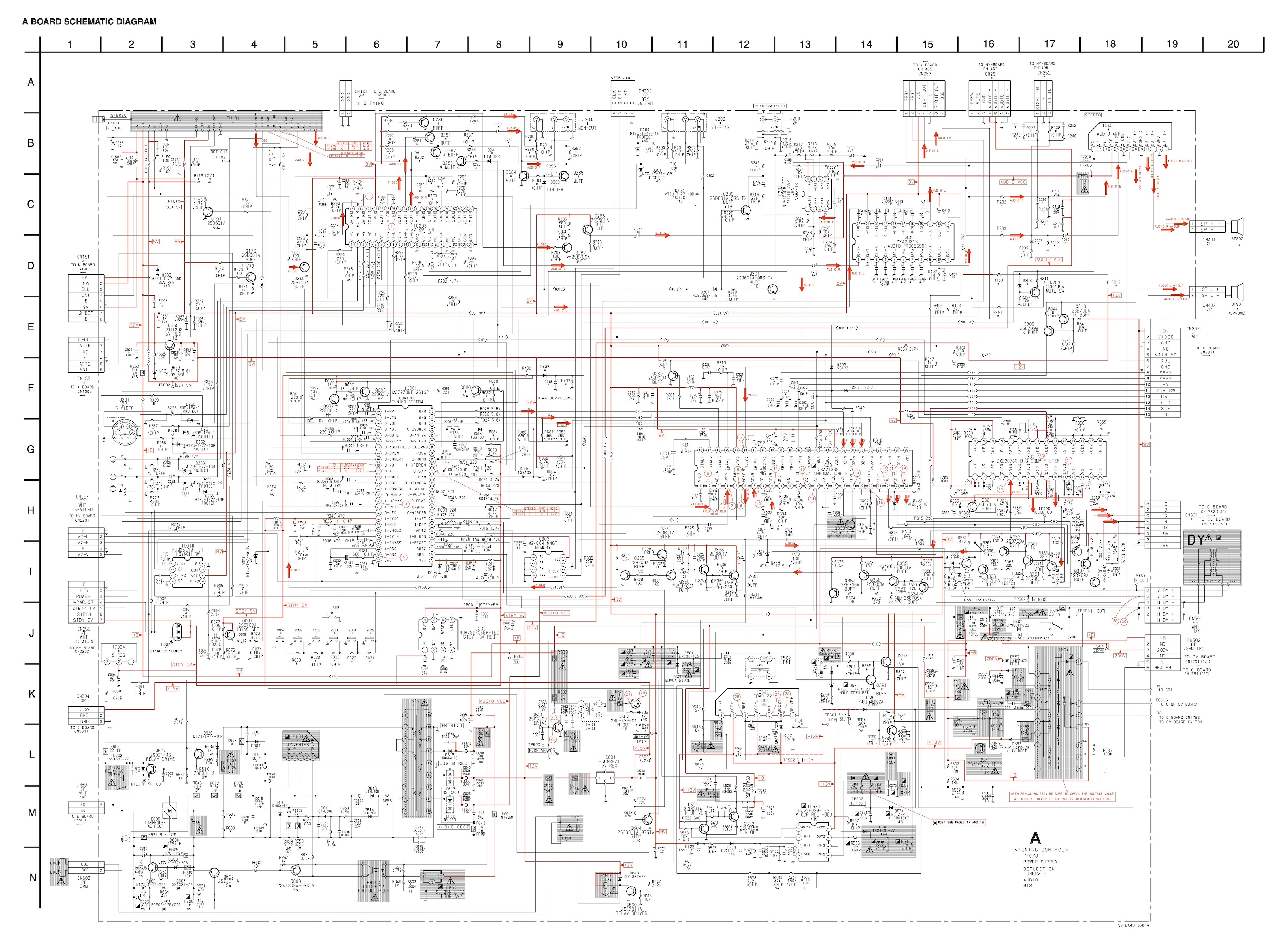
RGB mux diagram
Prepare the mux diagram. If you are building your own circuit, this diagram should help.
Chapter 1: No more dummy plug needed
We'll be using the diagram below for this modification. While it’s specifically designed for the KV-27S42, it is also compatible with the KV-27V42 and other 27" BA-4D chassis models that use luma for sync. However, this method does not apply to 20" or smaller BA-4D models, as they do not require luma for sync.
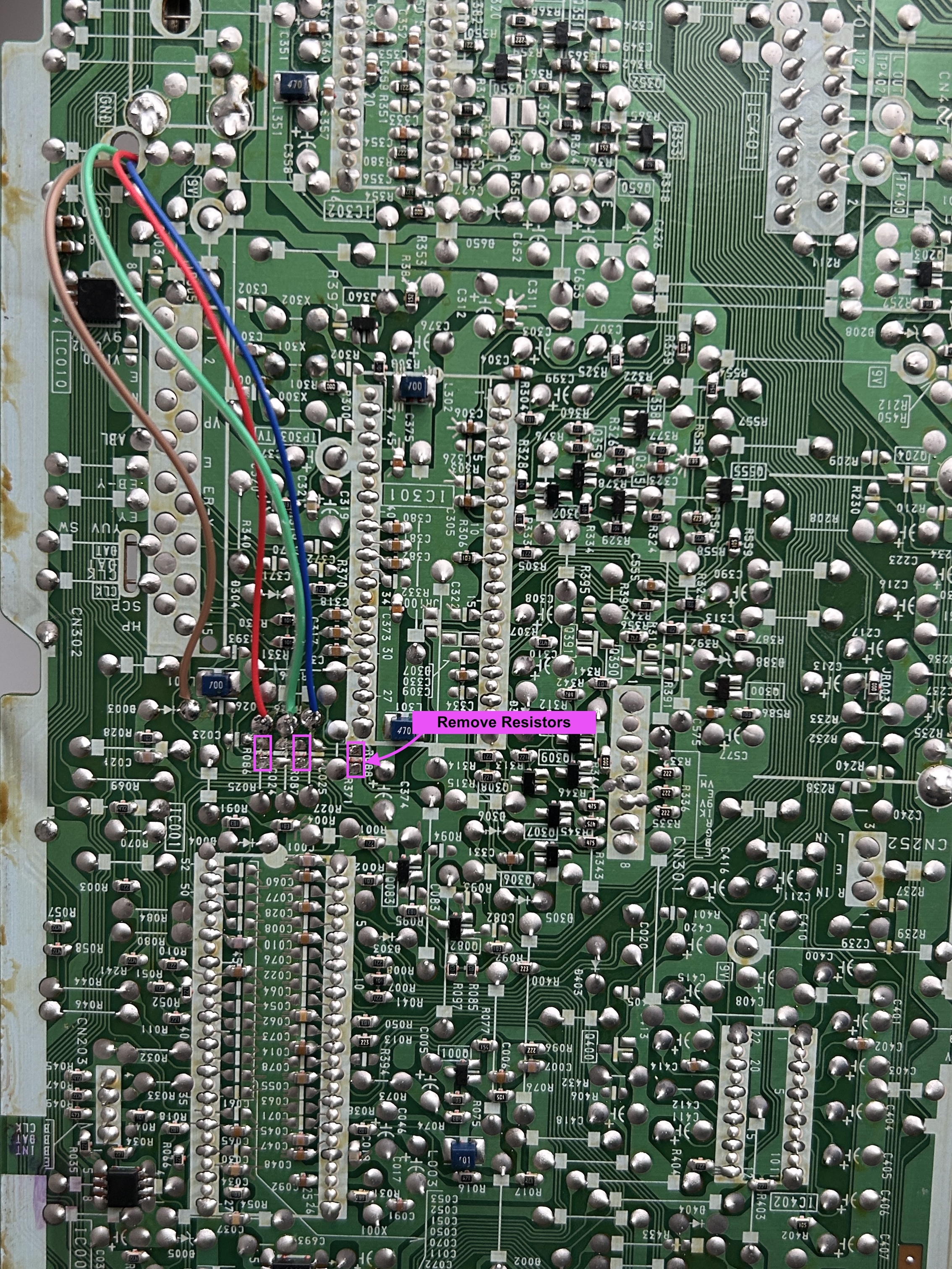
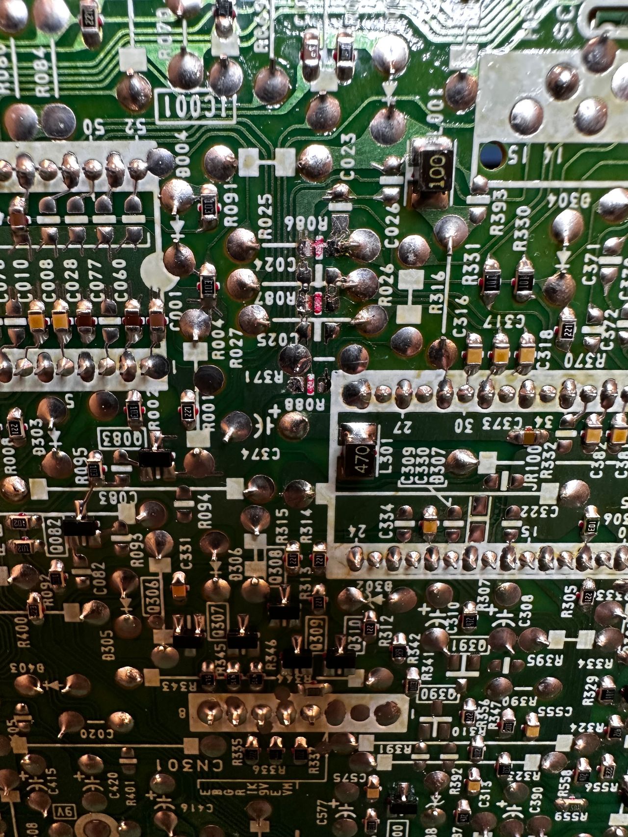
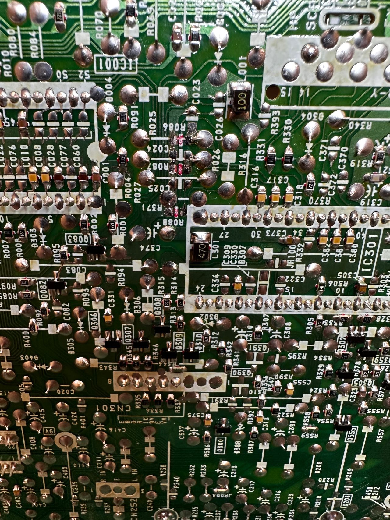
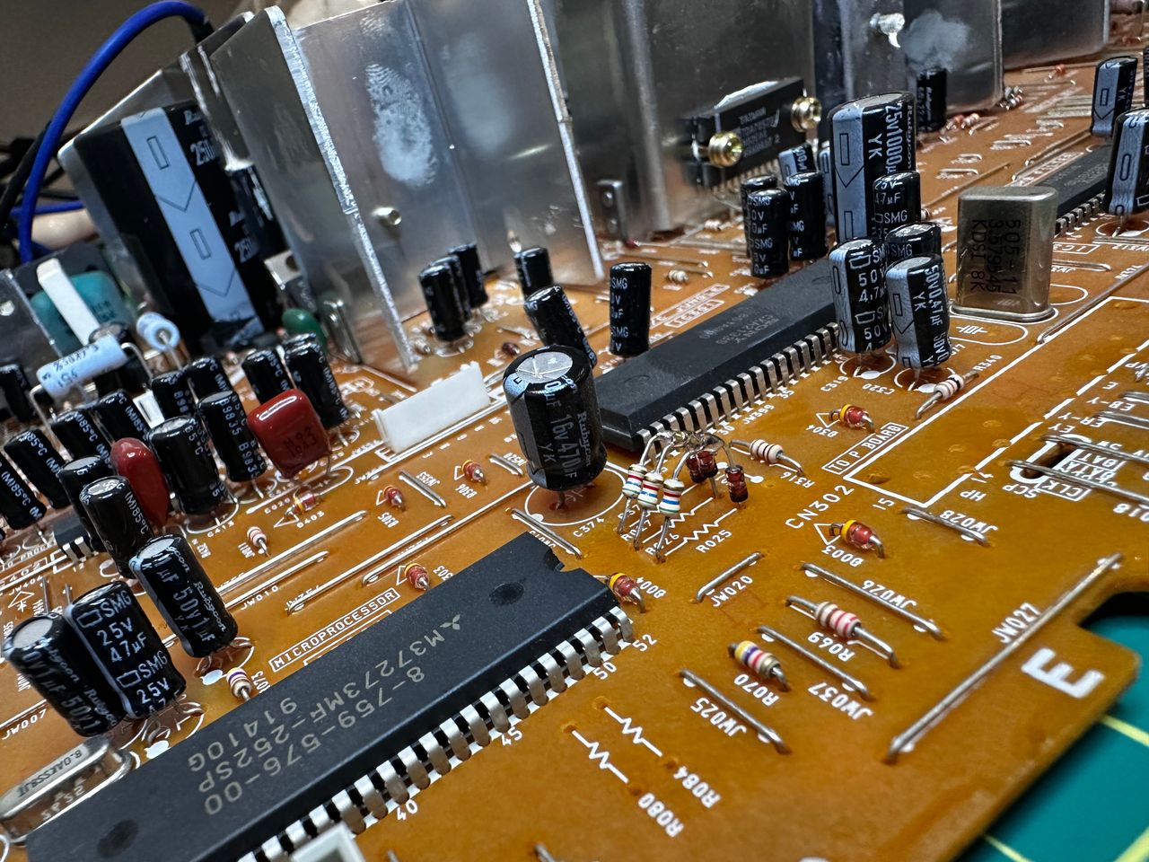
STEP 1: Remove RGB ground resistors
First we will remove the following components. So, nothing new here.
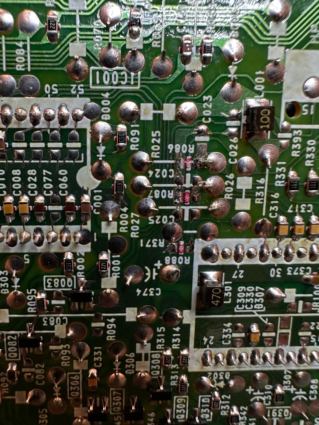
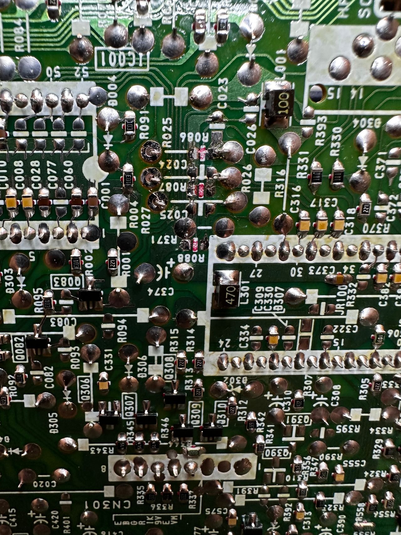
Remove the following components. RGB resistors to the ground. Please always measure and mark them, so that you know you are removing the correct partrs.
- R086 (680Ω) Red ground resistor
- R087 (680Ω) Green ground resistor
- R088 (680Ω) Blue ground resistor
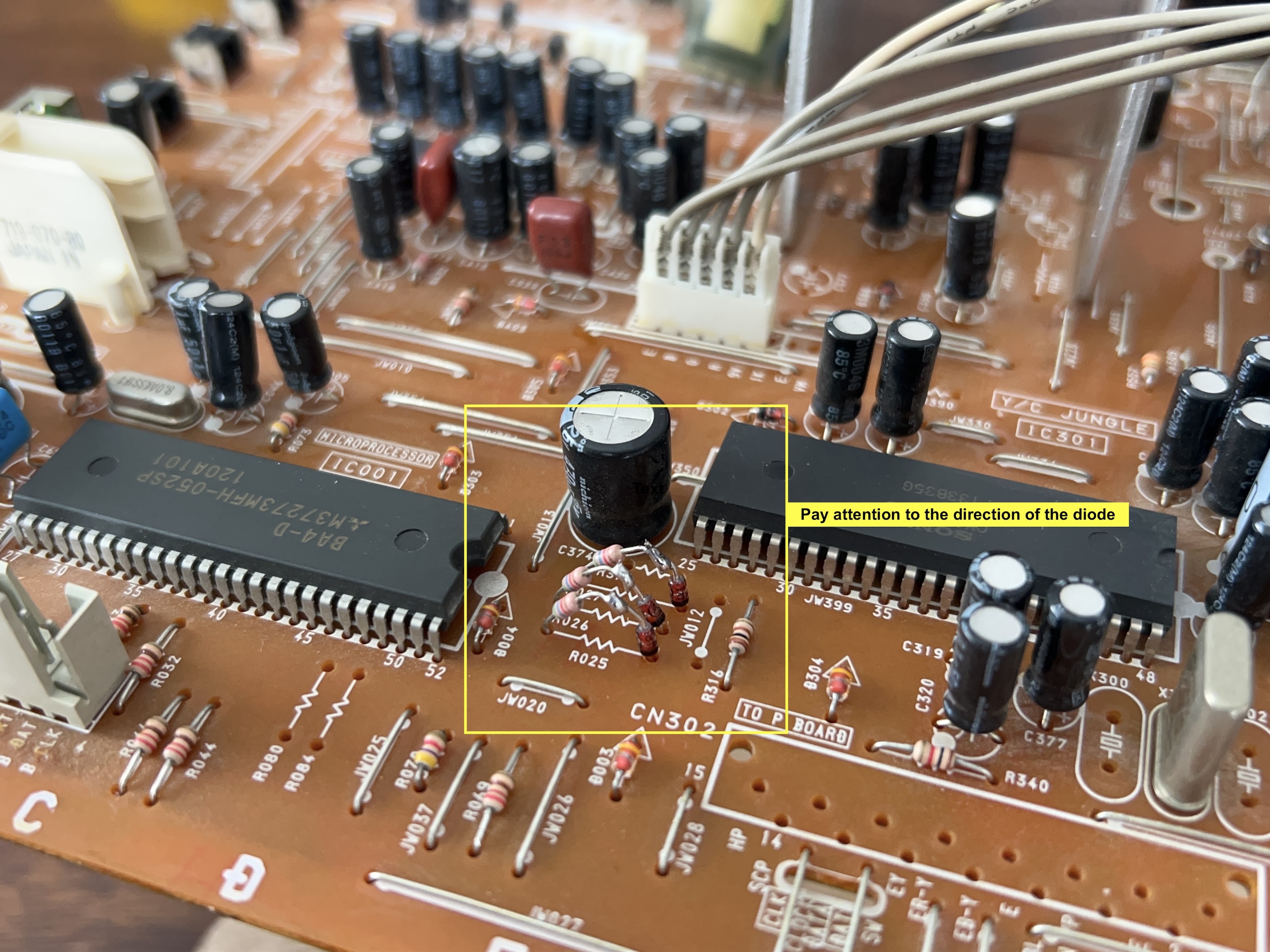
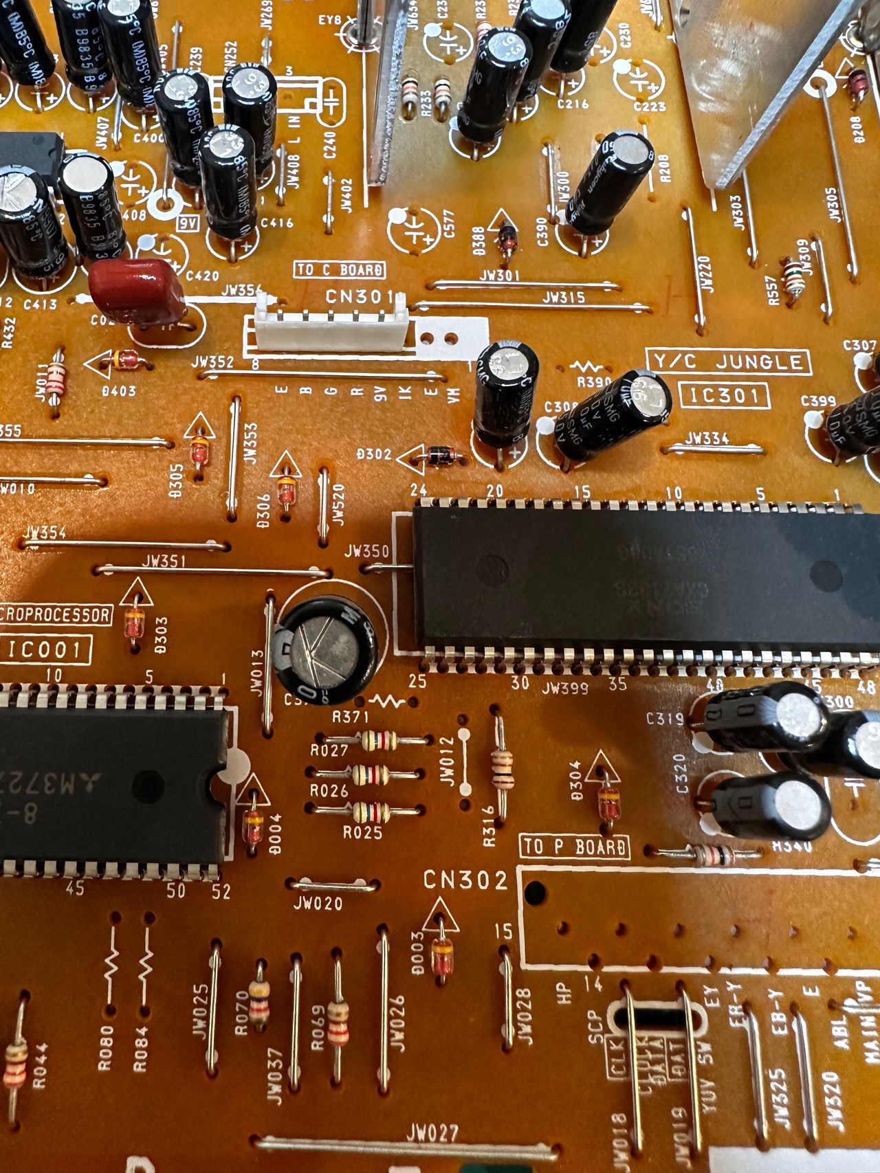
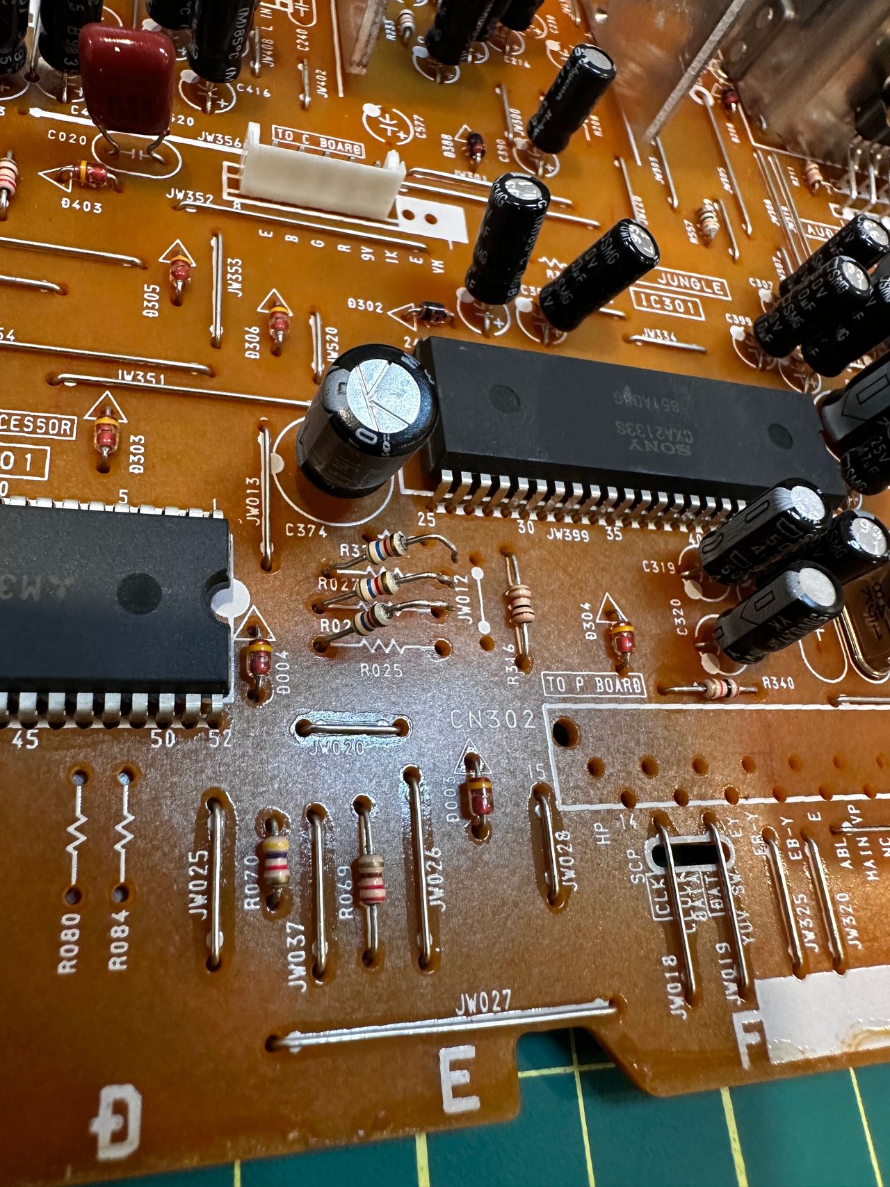
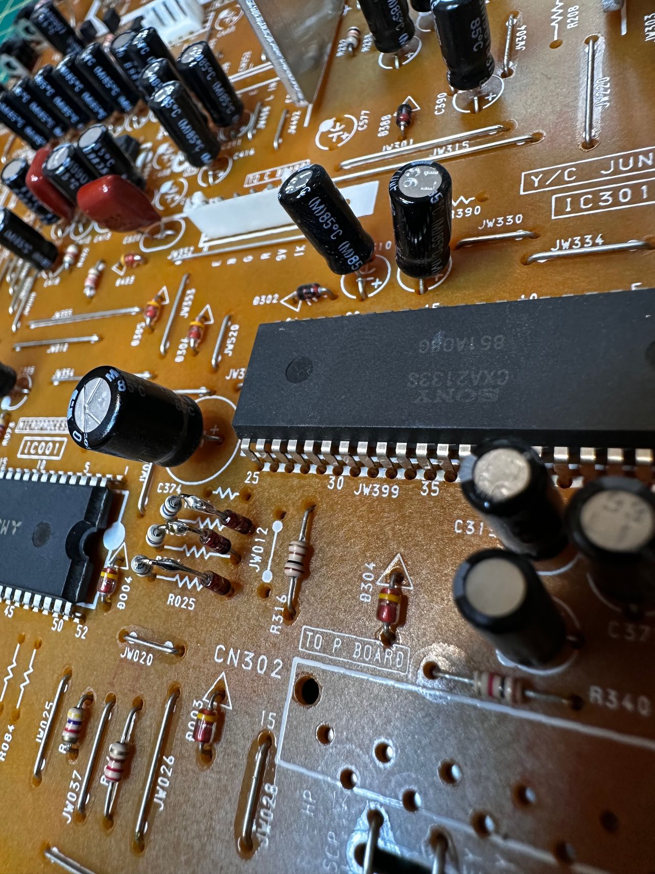
STEP 2: Add RGB inline diodes
To reduce interference, it is recommended to add these inline diodes. You will be lifting one side of the R025, R026, R027 and add diodes.
Pay attention to what side the diode is added and the direction of the diode stripe.
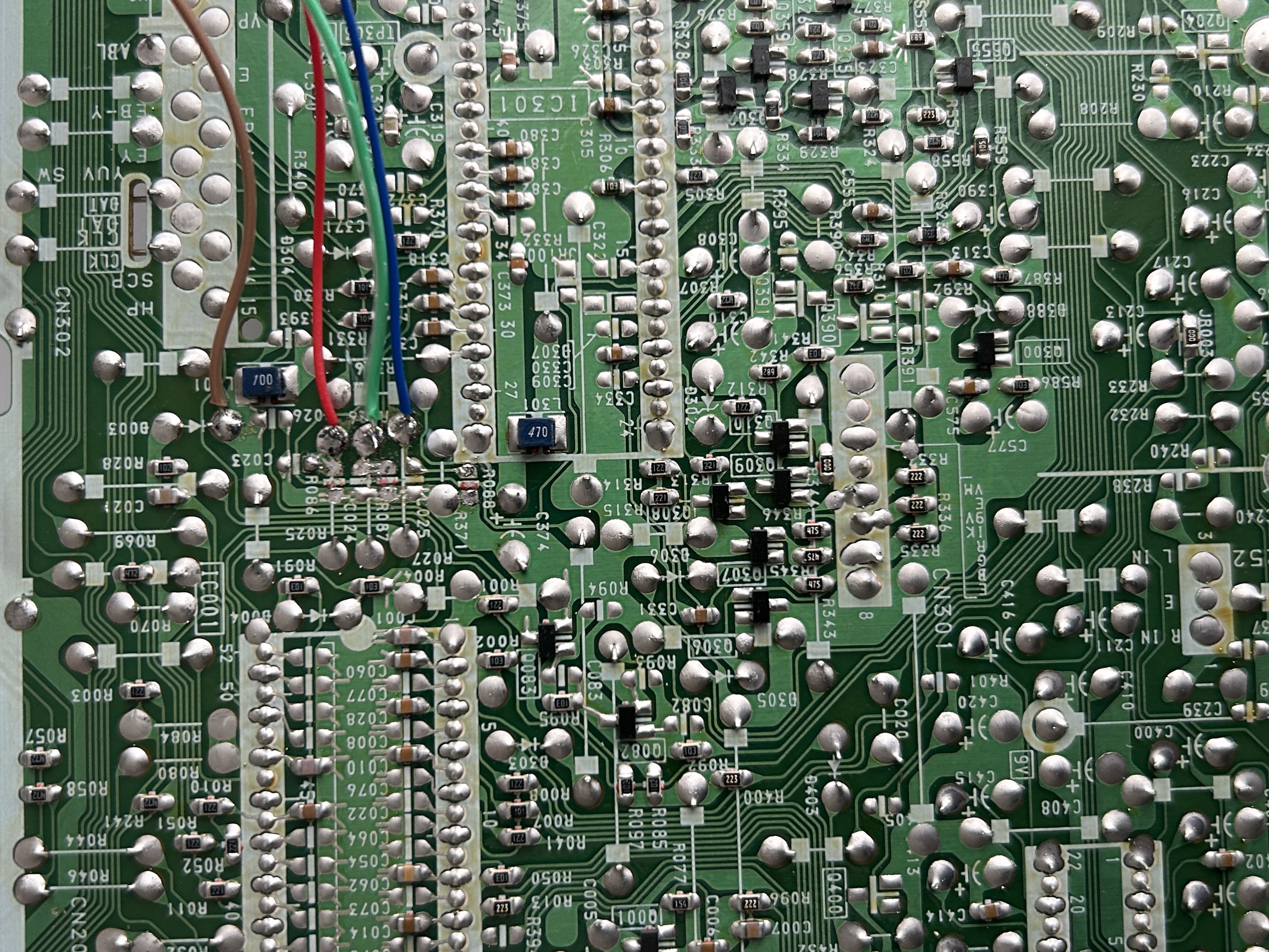
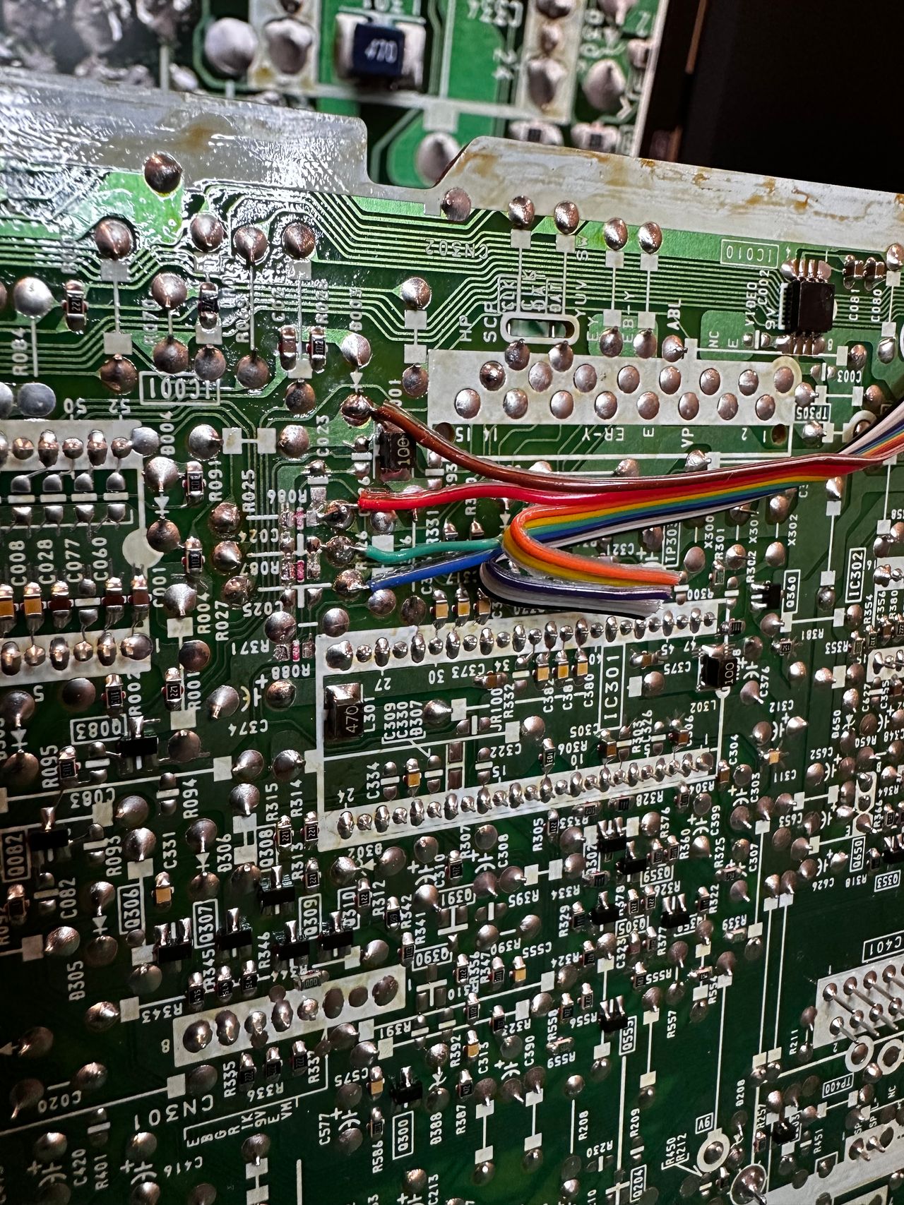
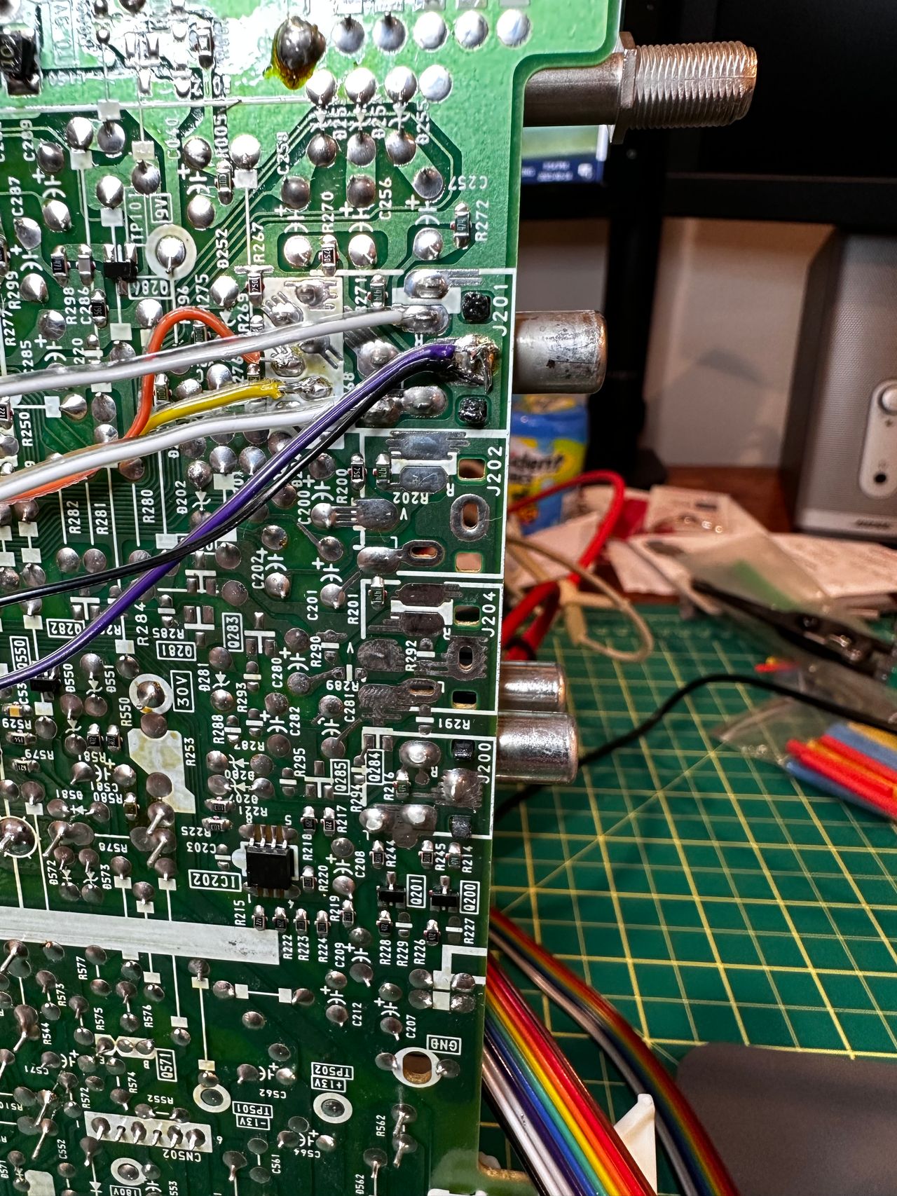
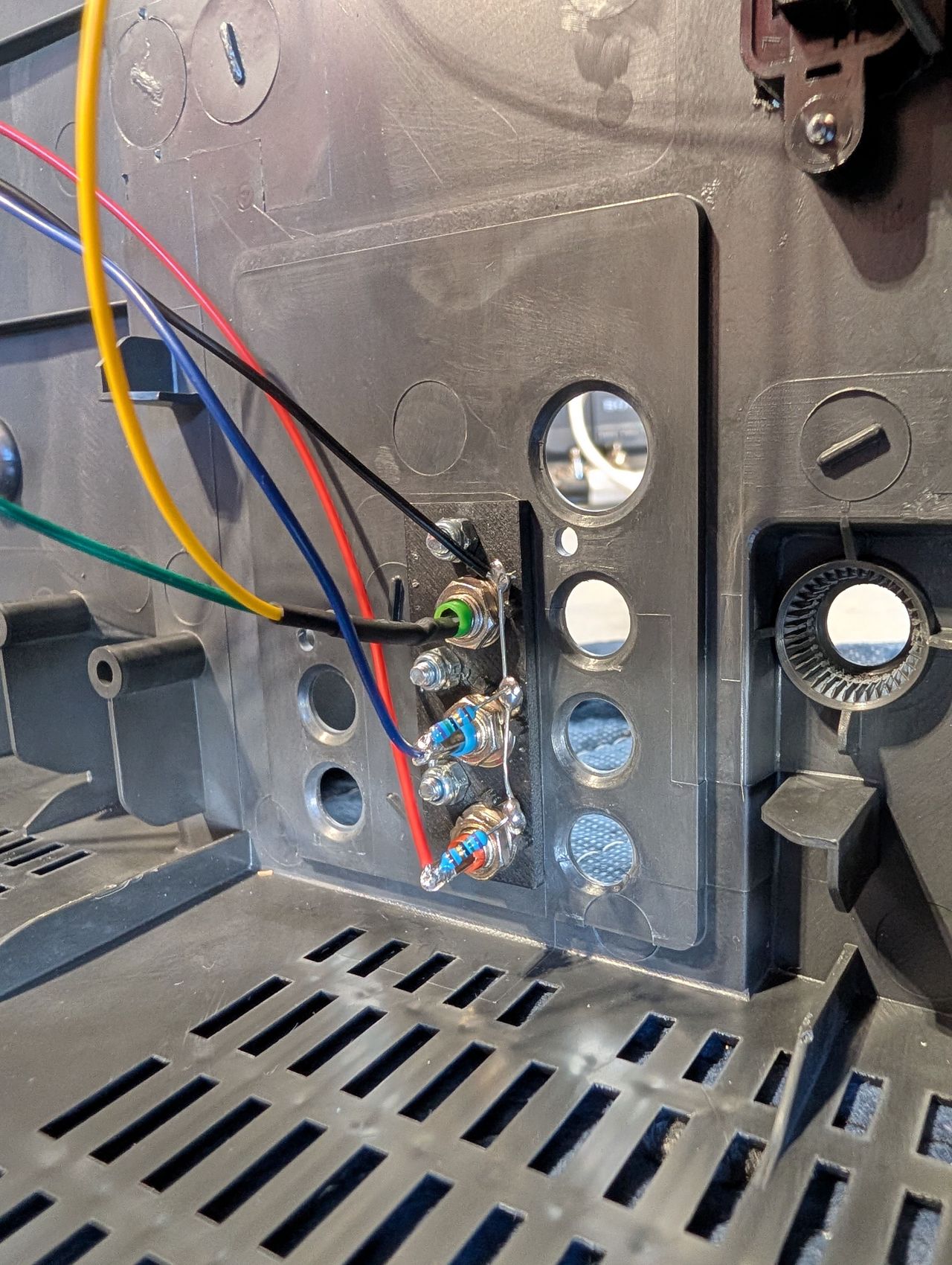
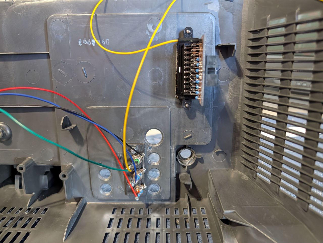
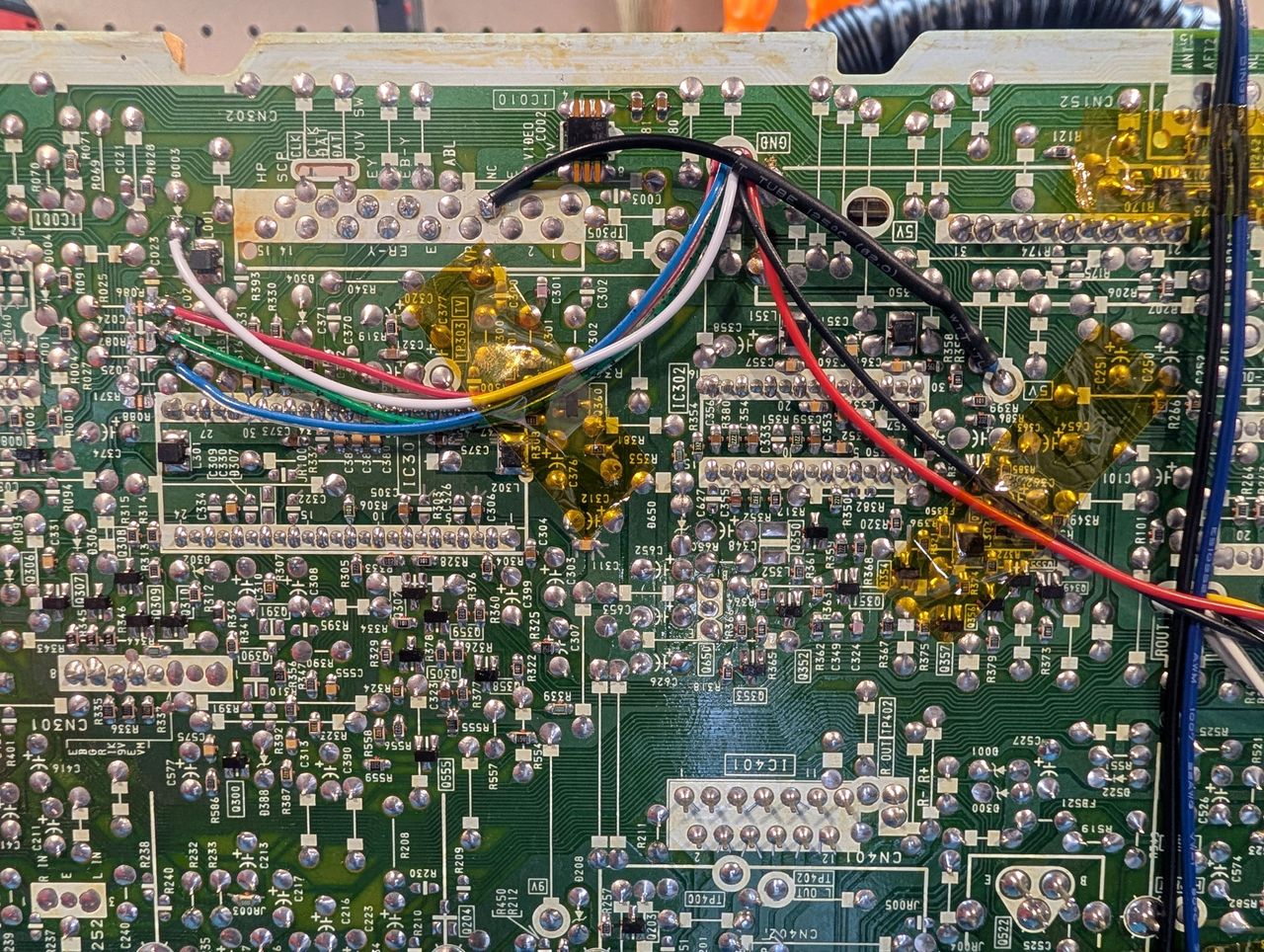
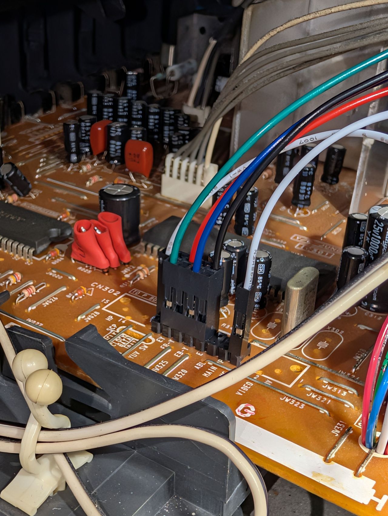
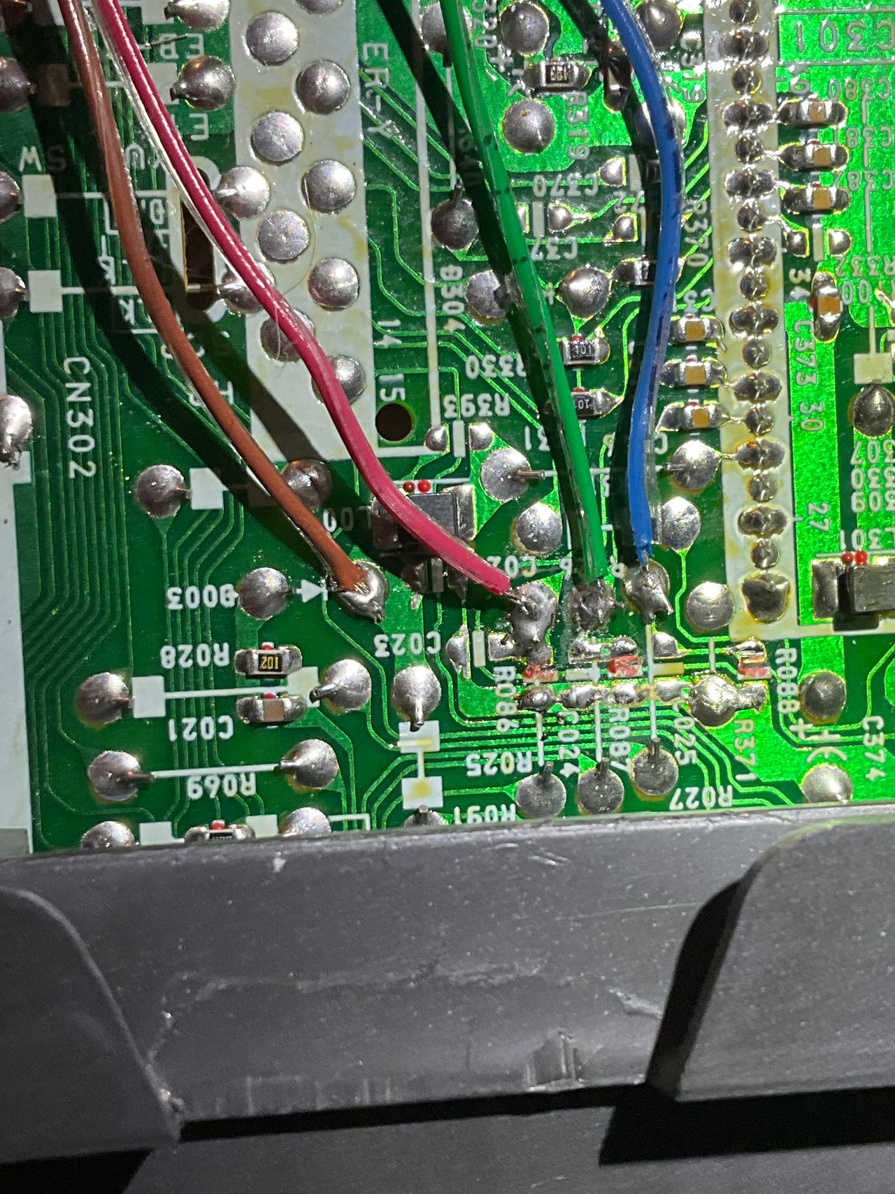
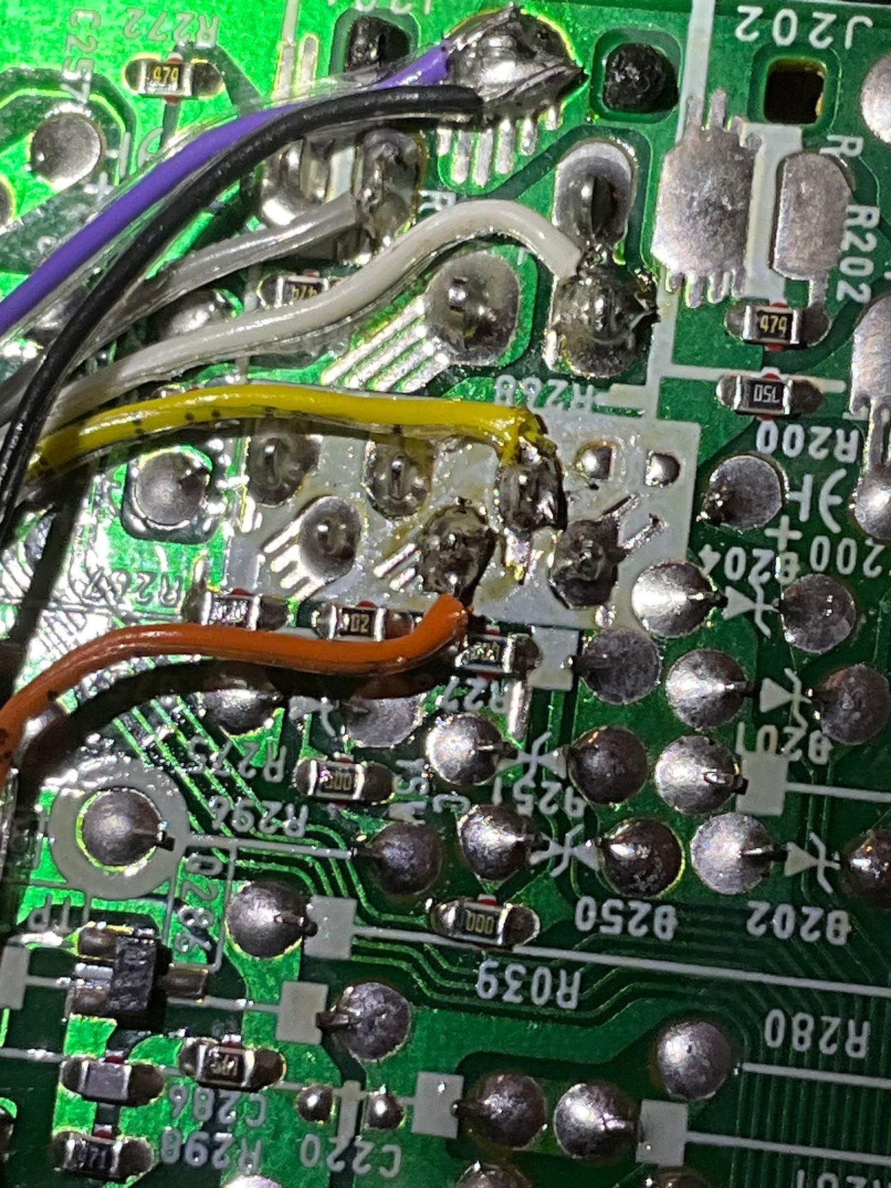
STEP 3: Attach R, G, B and blanking wires
Ensure that the R, G, B, and blanking wires are connected as shown in the picture.
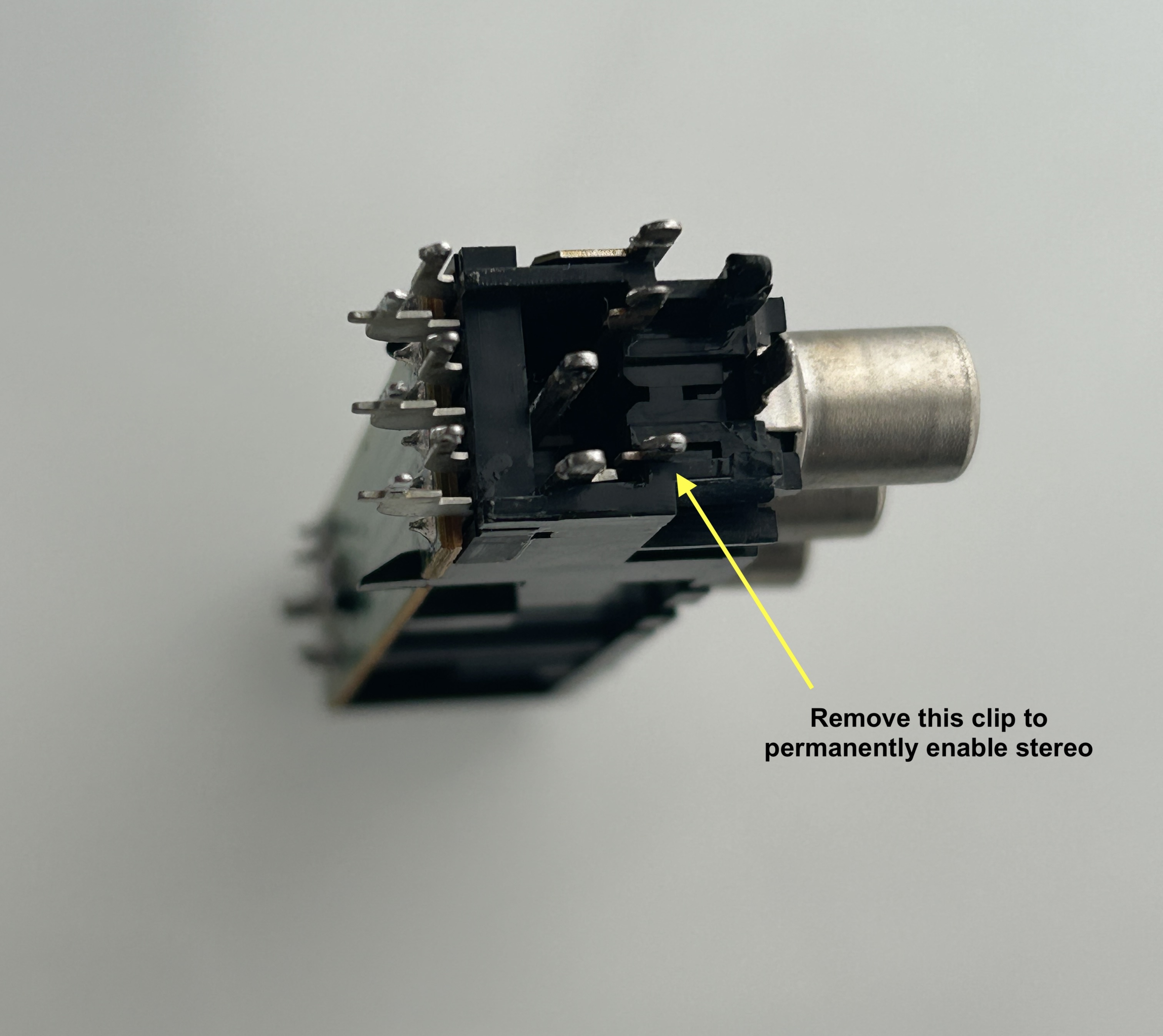
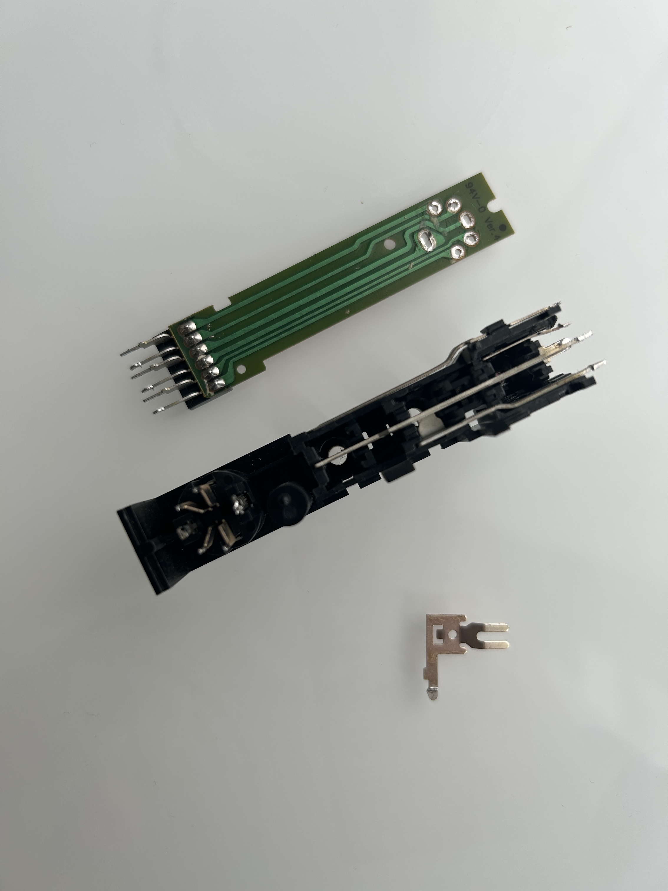
STEP 4: Permanently enable stereo
Permanently enabling stereo can be a bit tricky, especially if you're using Video 1 input sync for RGB. Here are your options:
- Option 1 (Recommended): Simply insert a plug into the red RCA port. This is the easiest and most effective method.
- Option 2 (Not Recommended): Cut the trace to force stereo. However, this isn't as simple as a single cut—you'll need to cut the trace from both sides and then resolder the right audio connection back into the circuit.
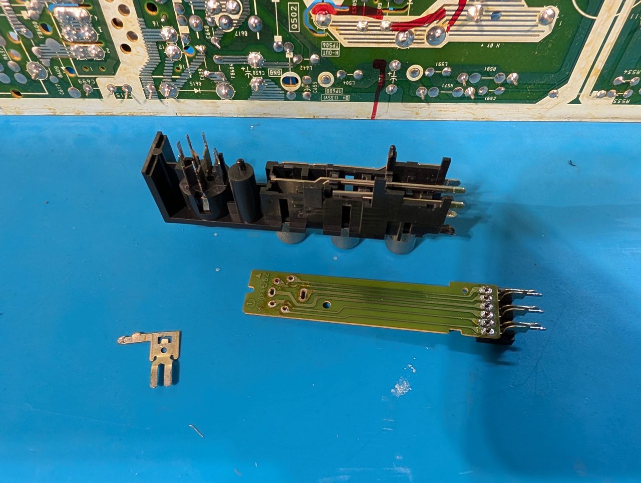
- Option 3 (High Effort, Cleanest Solution): If you have a desoldering tool, you can remove the physical clip that forces mono when nothing is plugged into the red RCA port. This is the most involved method but results in a clean and permanent solution.
Below, you'll find pictures demonstrating Option 3.
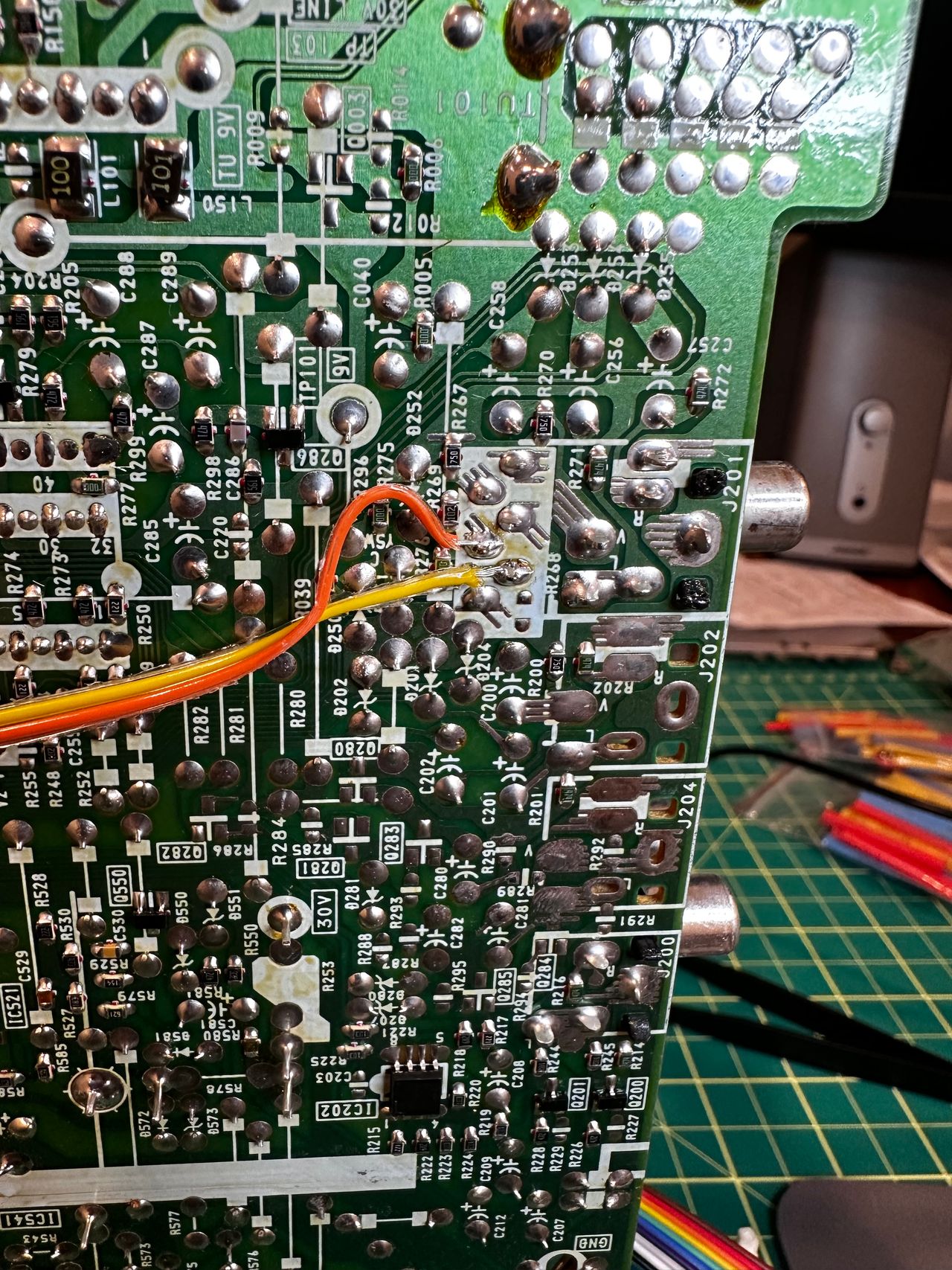
STEP 5: Connect sync and s-video detect
Finally, we have a purpose for the orange wire! In other mods, you may have seen it labeled as auxiliary or simply grounded as unused.
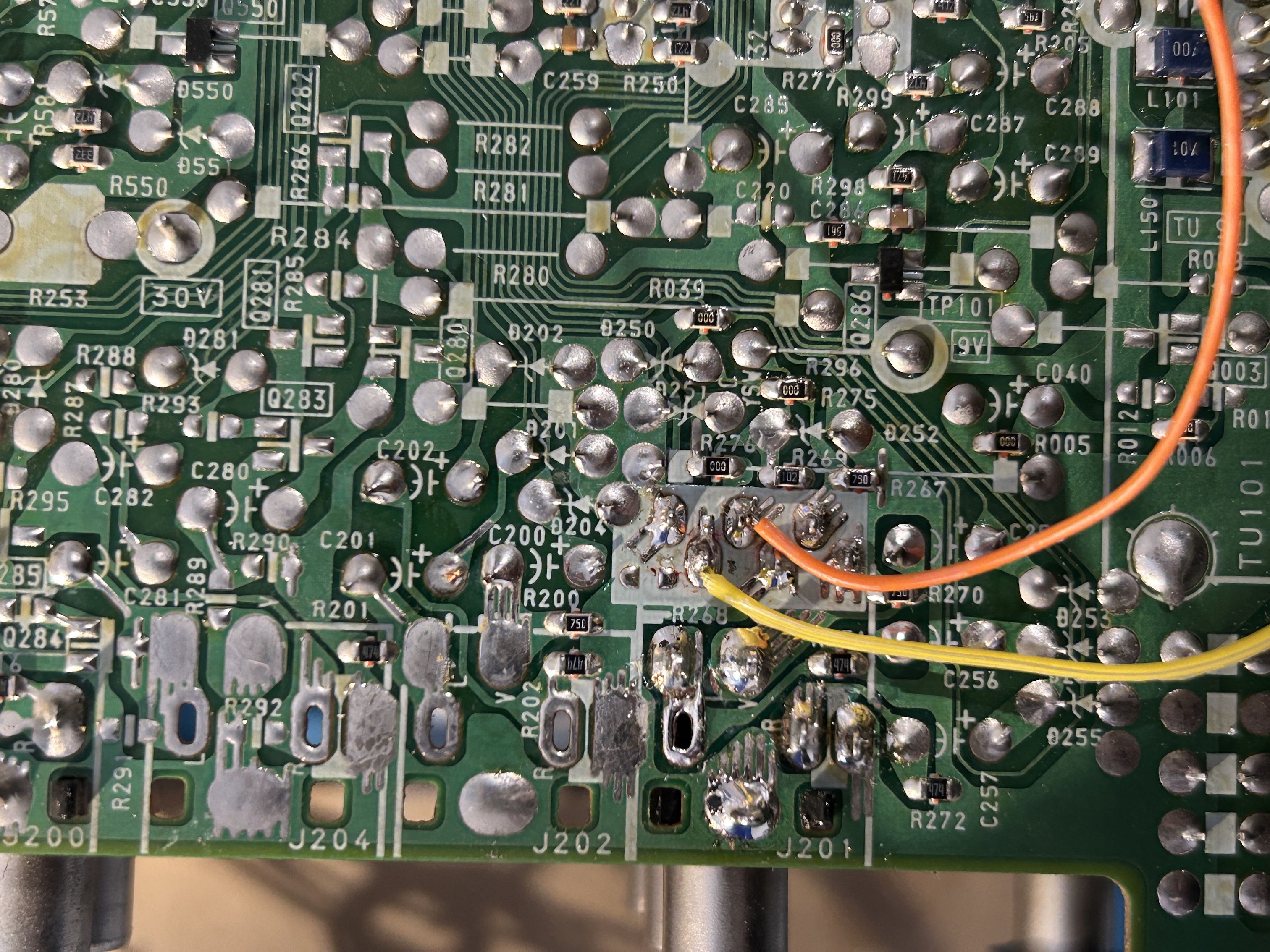
- Yellow wire: Used for sync.
- Orange wire: Functions as S-Video detect, automatically grounding when a blanking signal is detected from the SCART input.
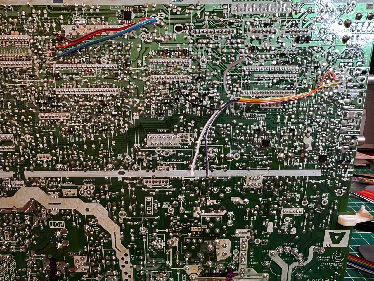
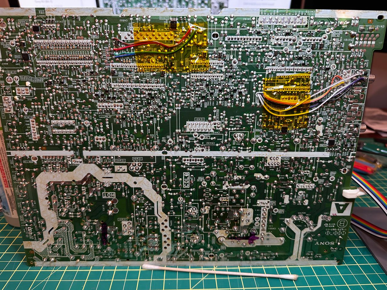
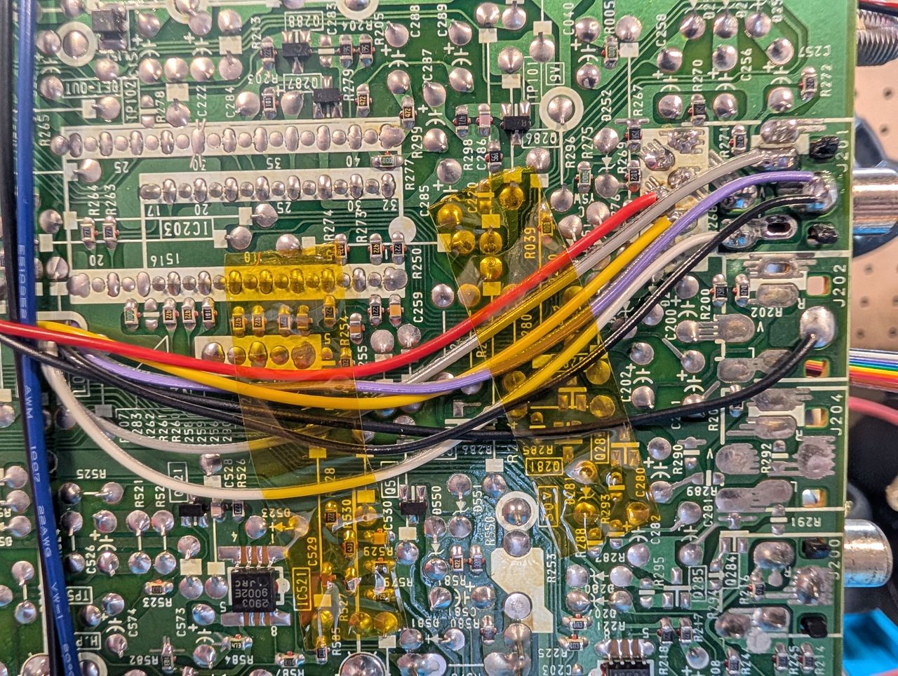
STEP 6: Audio and ground wires
Now wire the audio wires.
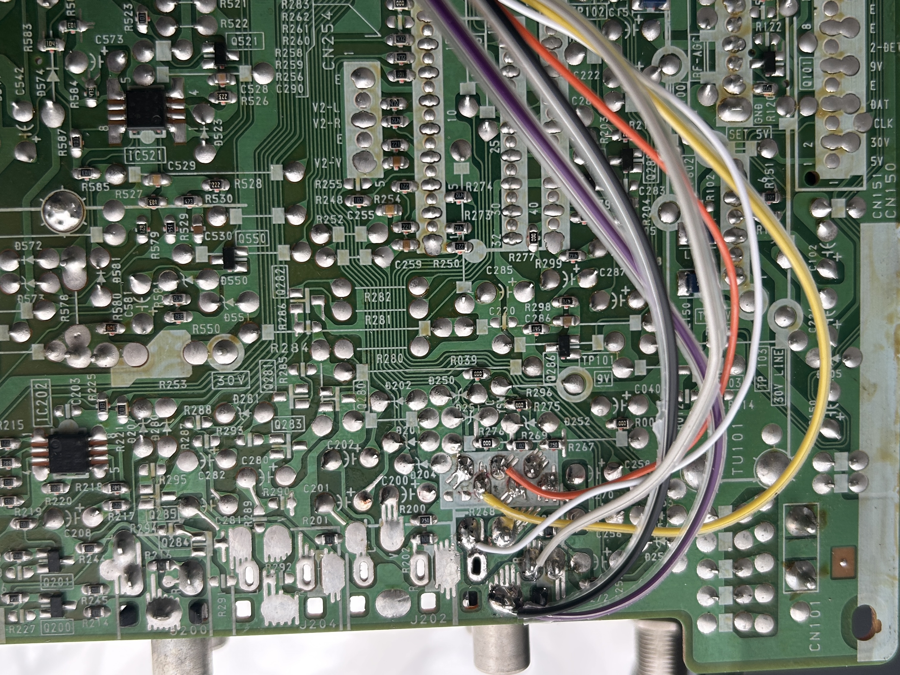
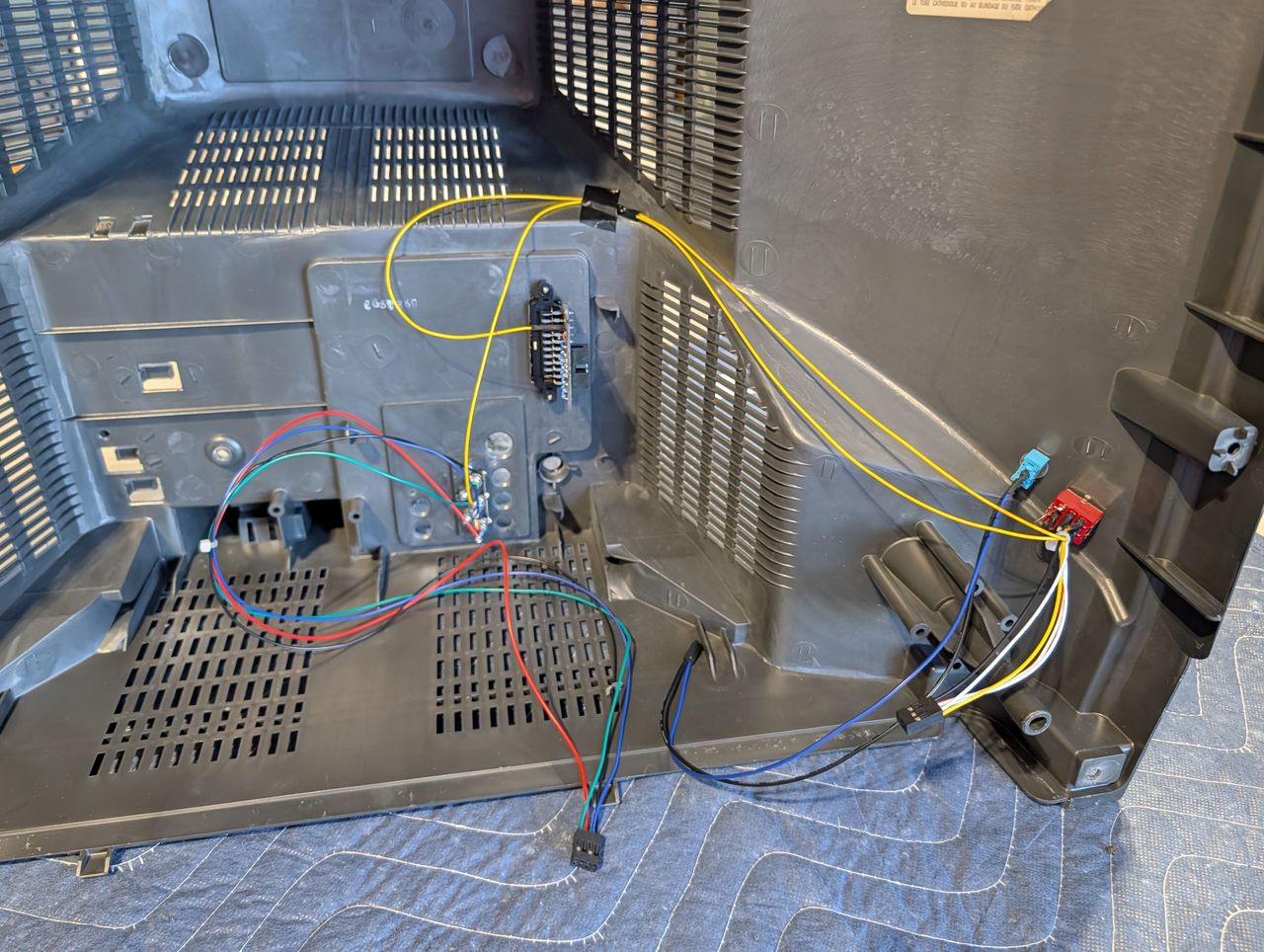
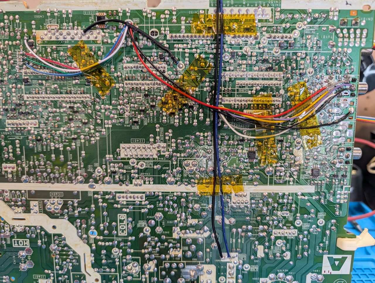
Final full mod picture.
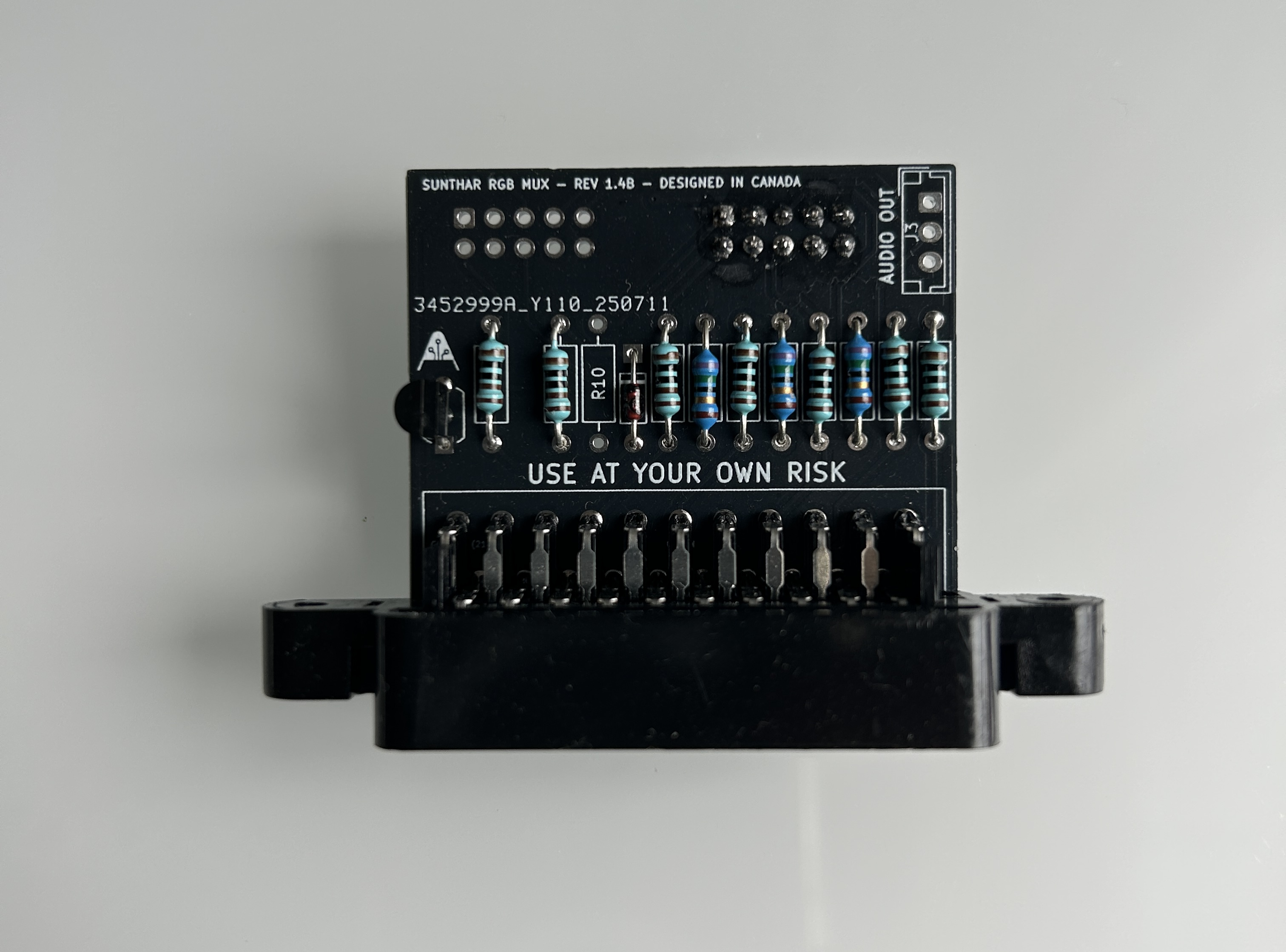
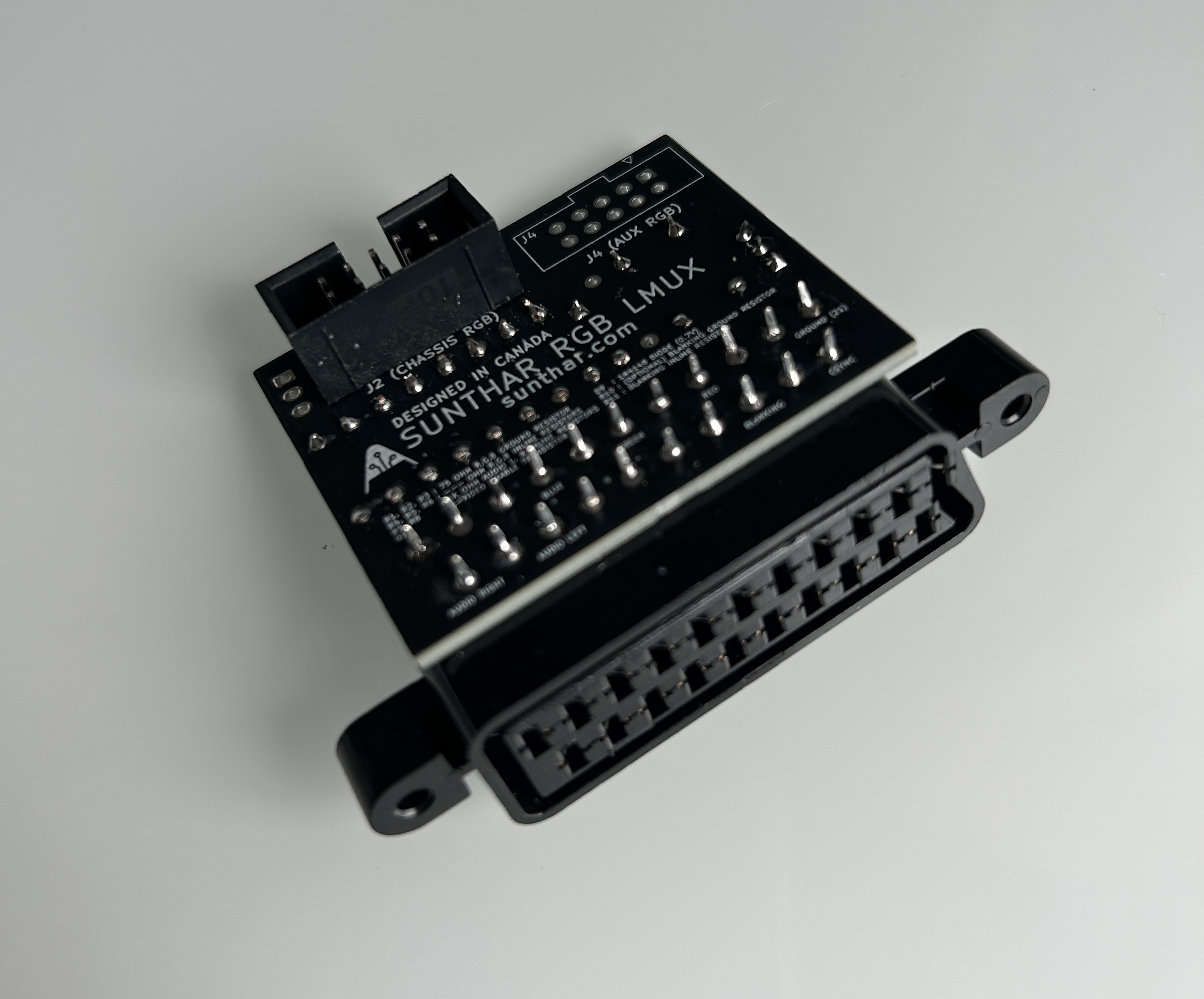
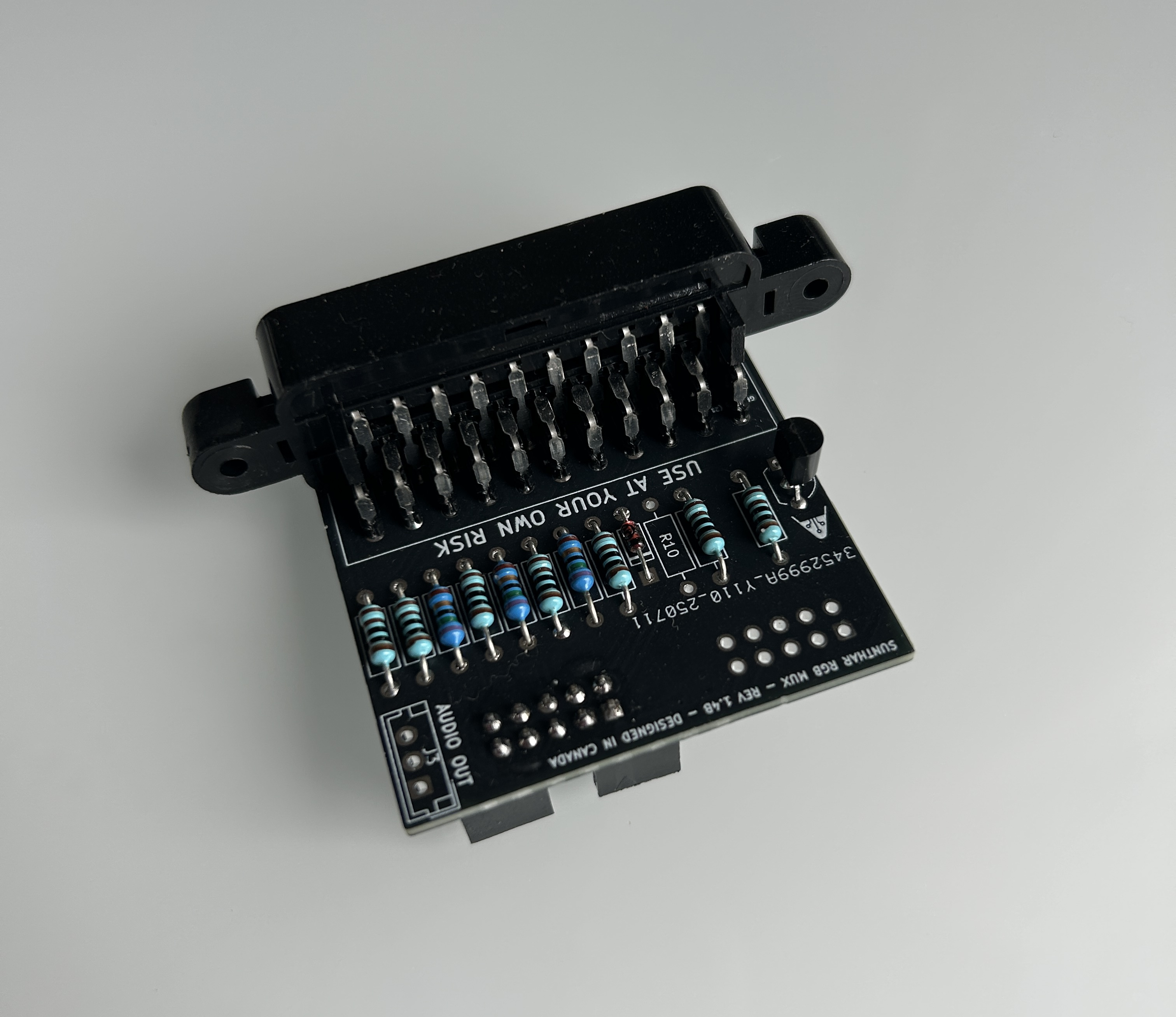
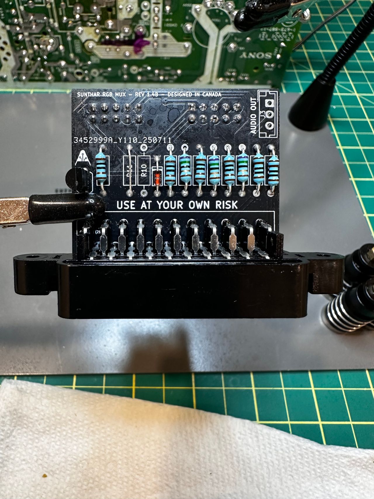
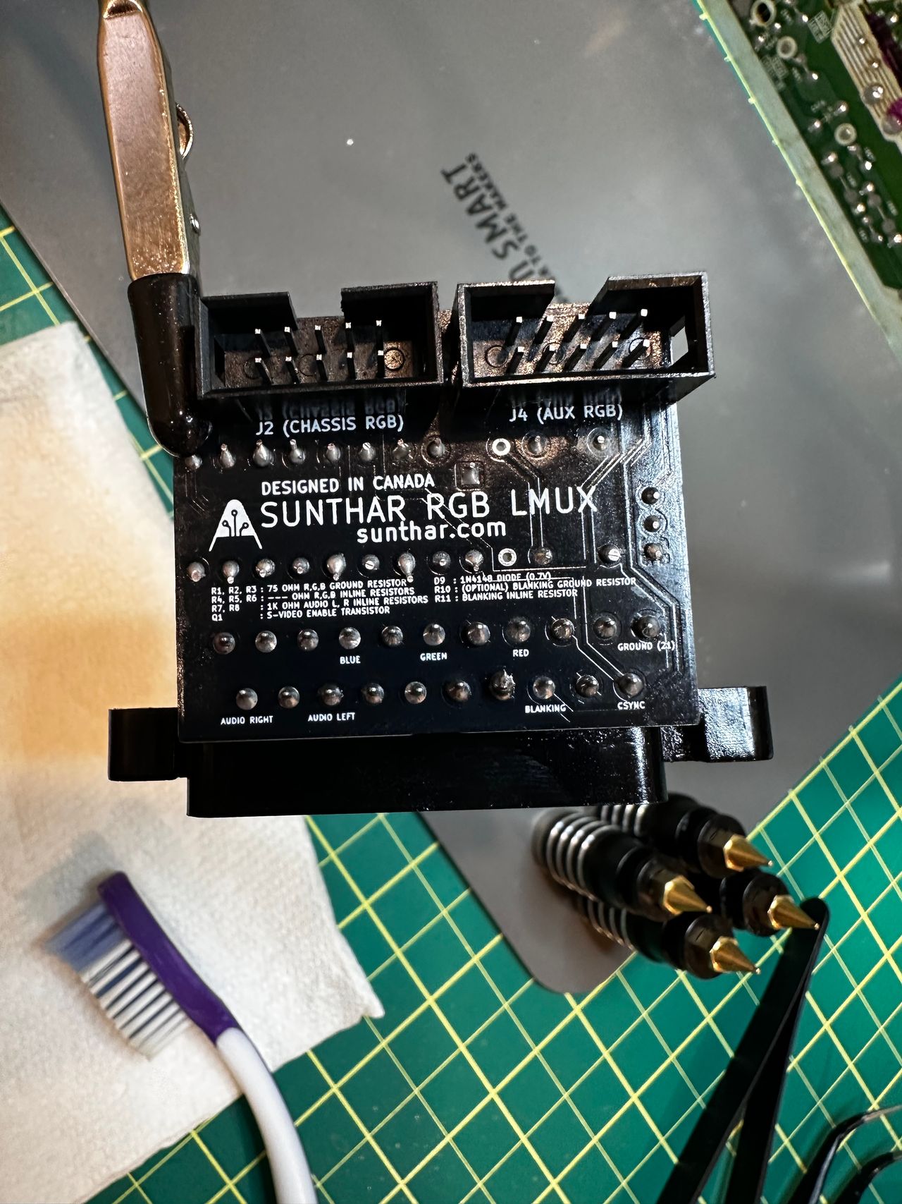
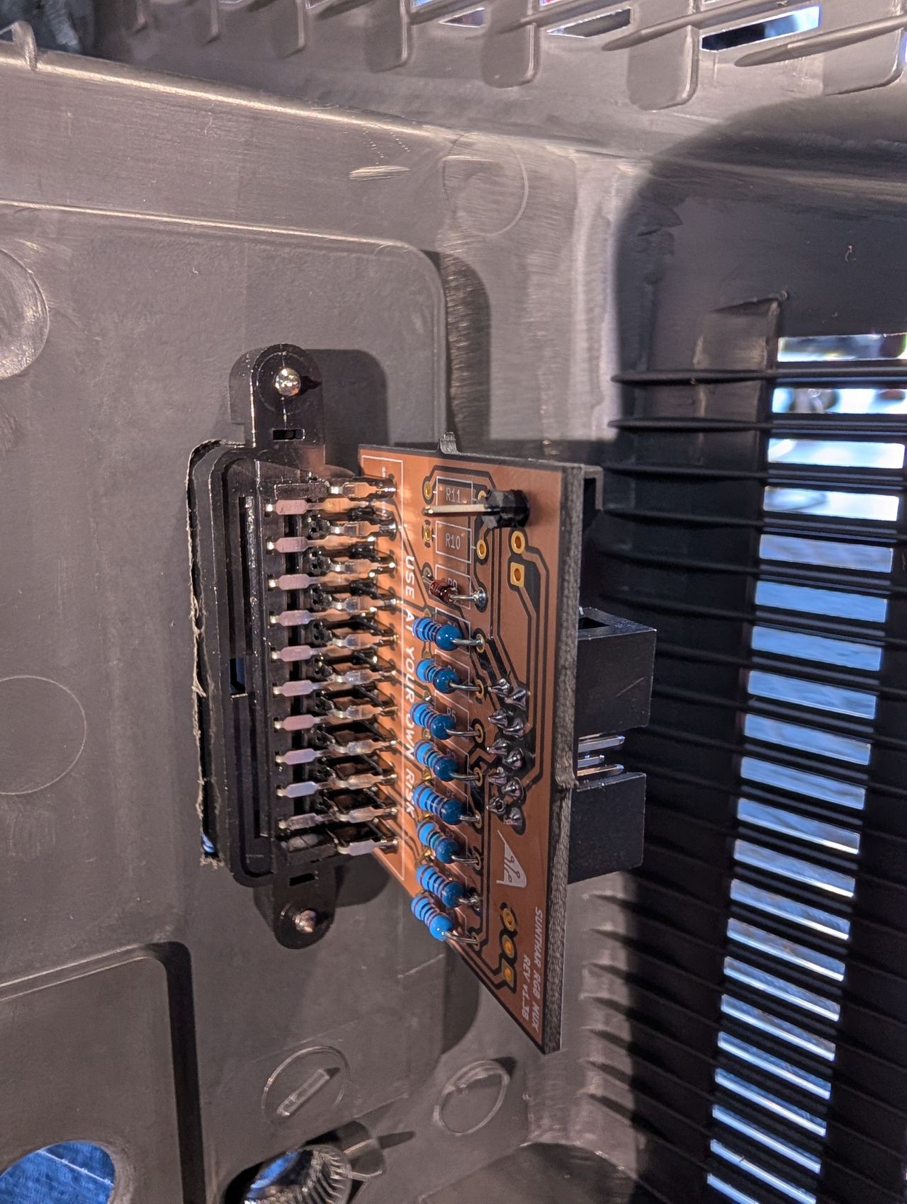
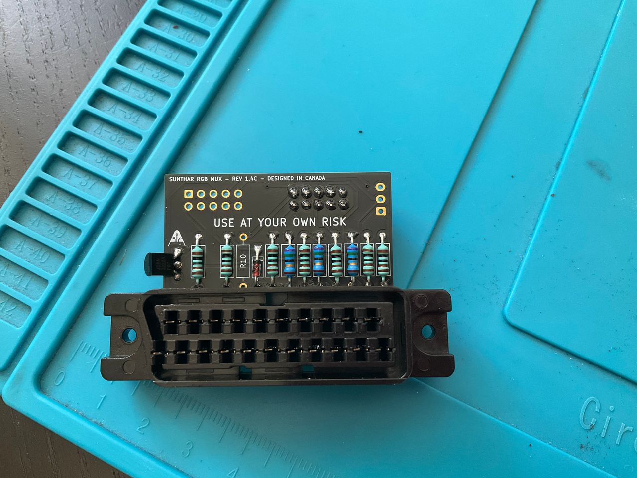
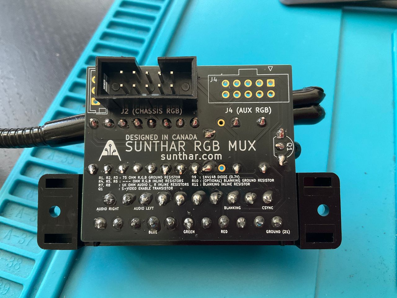
STEP 7: Introducing the MUX 1.4B board.
Latest v1.4B board packs some useful features:
- Automatic S-Video Detection – Uses a PN2222A transistor to handle S-Video detection, eliminating the need for a dummy S-Video plug, which was a hassle.
- Auxiliary RGB Port – Adds an additional RGB input, allowing for an extra SCART or 8-pin mini DIN connection.
The board is the same size as the 1.3B/1.3C models.
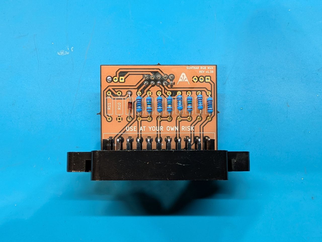
STEP 8: Build your MUX board
This mod uses the RGB mux board. This is optional, but will make your mod easier and stable. You can also create the circuit presented in the schematics above without the board. Please also checkout the mux calculator to play with your own values.
| On Sony CRT Chassis | KV-27S42 |
|---|---|
| CRT RGB inline resistor | 5.6kΩ |
| CRT RGB ground resistors removed | 680Ω |
| 0.1μF caps replaced | No |
| Add diodes on chassis RGB lines? | Yes |
| Add blanking diode on chassis | No |
| RGB mux board | KV-27S42 |
|---|---|
| Mux board RGB termination (R1, R2, R3) | 75Ω |
| Mux board RGB inline resistors (R4, R5, R6) | 1kΩ |
| Mux board Audio LR (R7, R8) | 1kΩ |
| Mux board blanking diode (R9) | 1N4148 |
| Mux board blanking ground resistor (R10) | open |
| Mux board blanking resistor (R11) | 1kΩ |
| Mux board transistor base resistor (R12) | 1kΩ |
| Mux board transistor (Q1) | PN2222A |
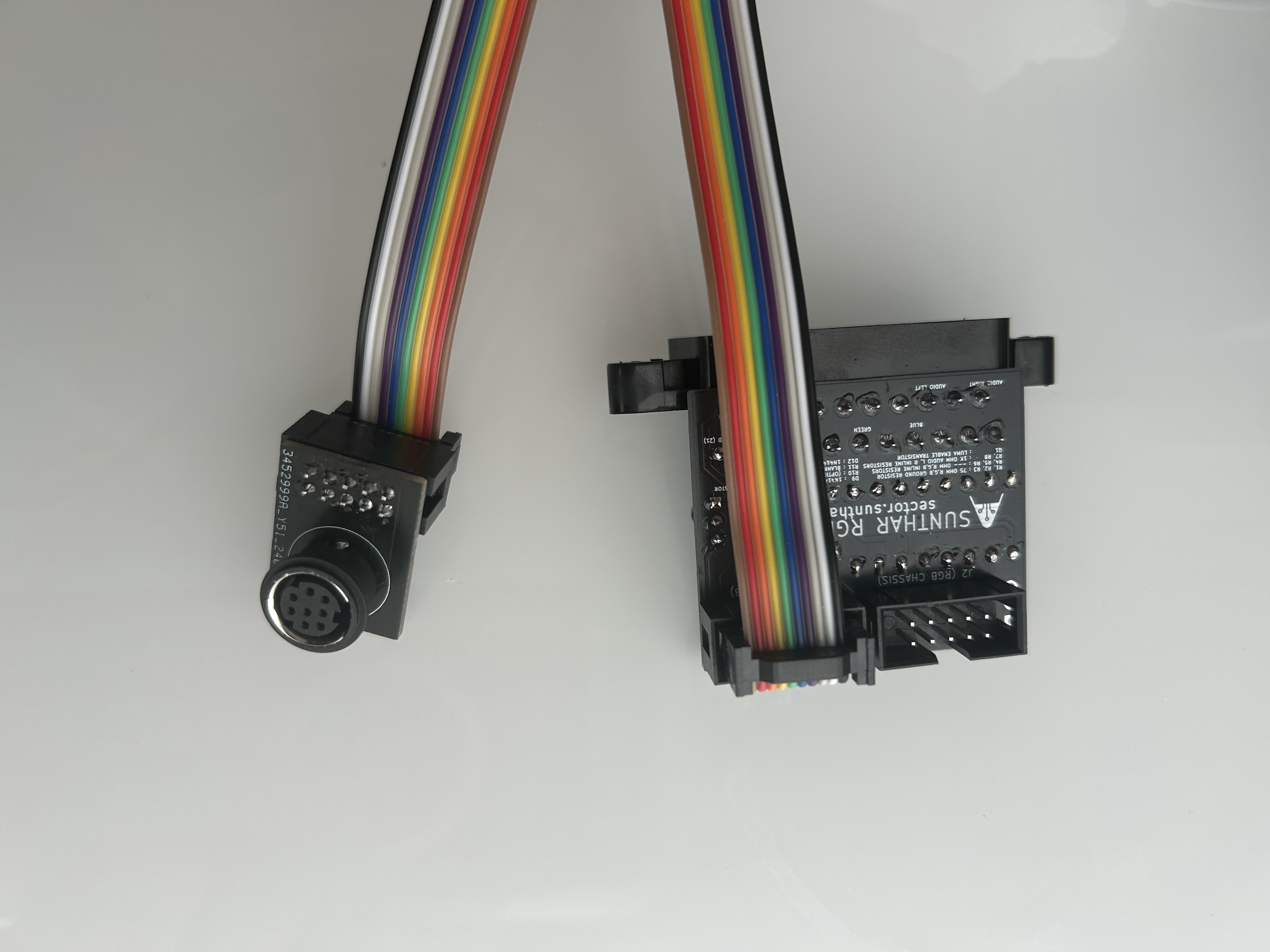
Compatible mux boards:
You can connect a second XRGB input using the auxiliary input through a 10-pin IDC connector on this board.
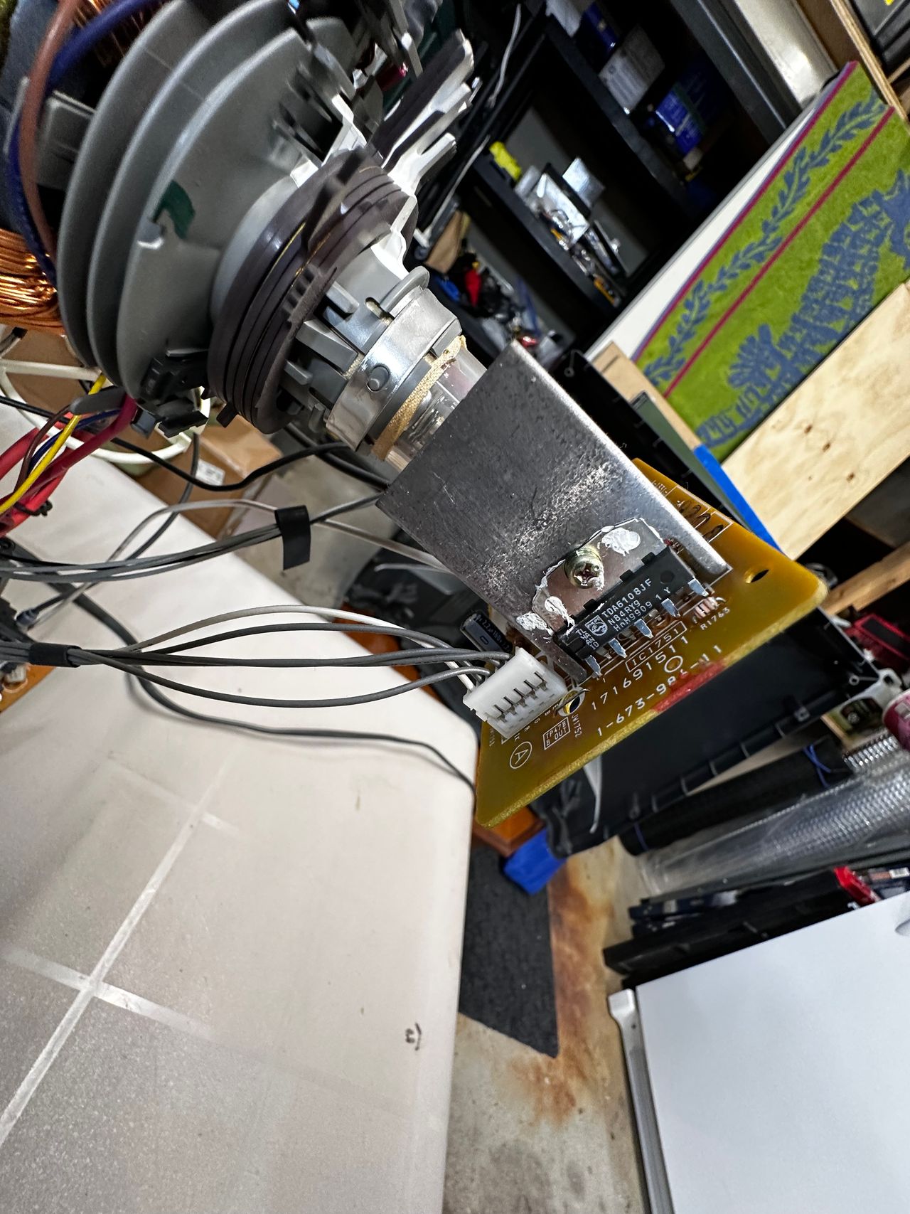
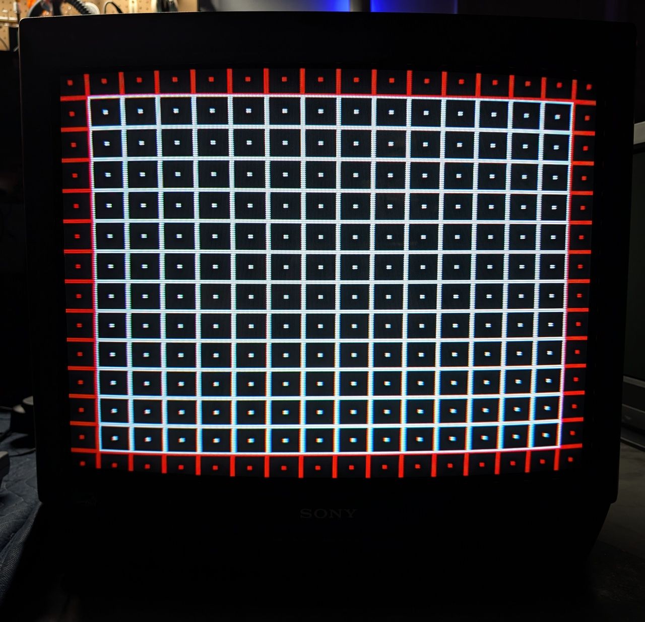
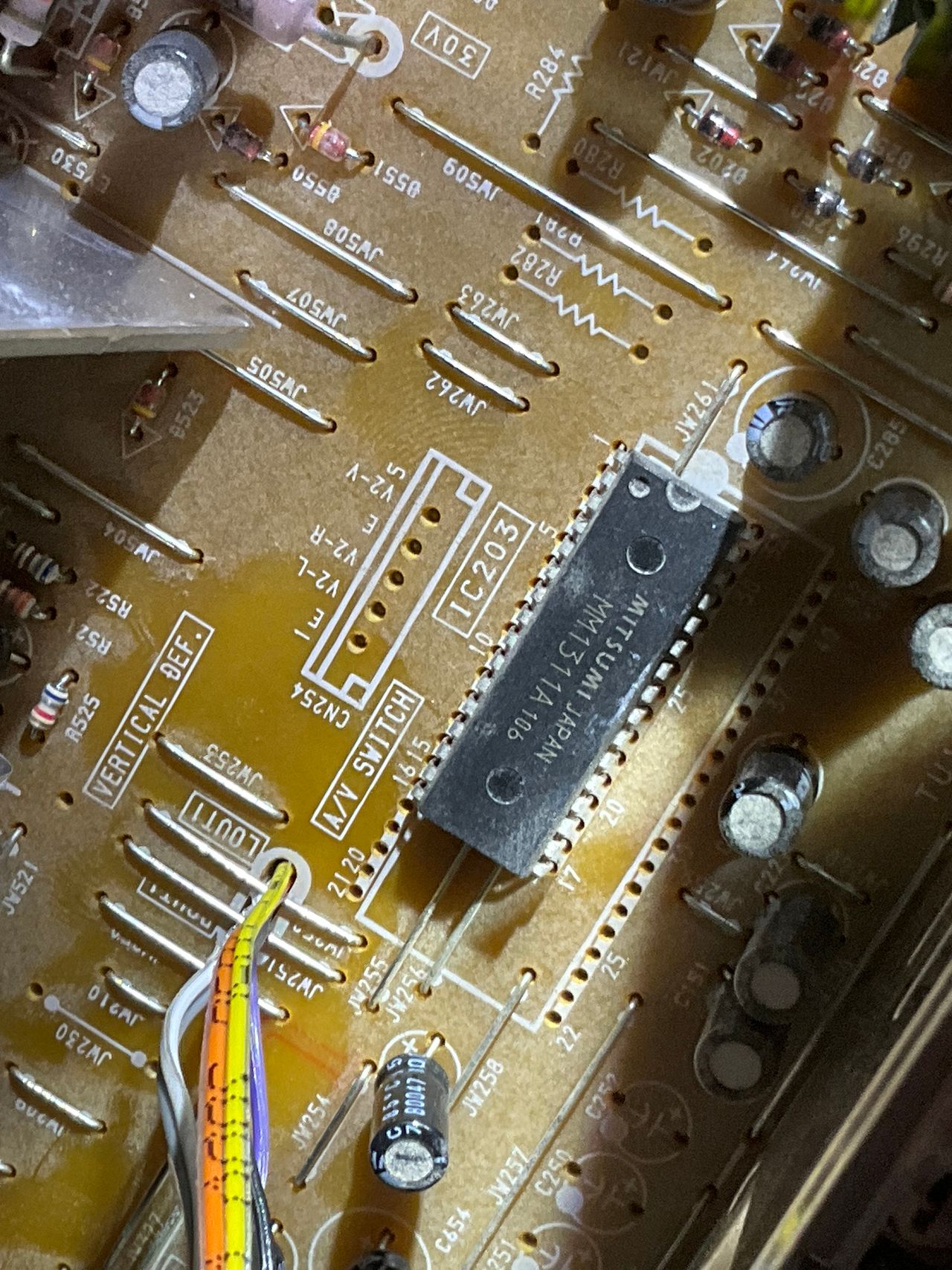
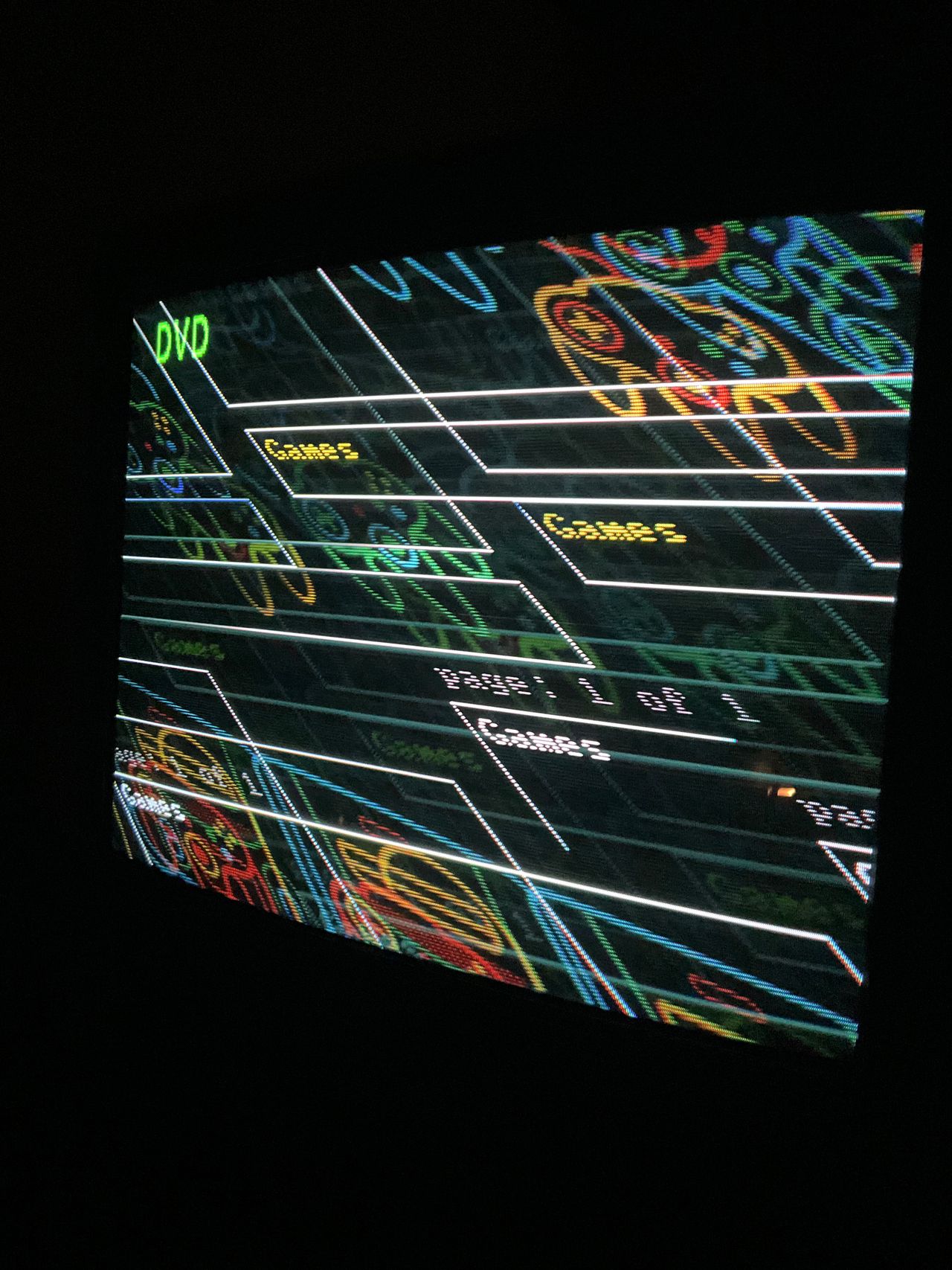
Sync issues
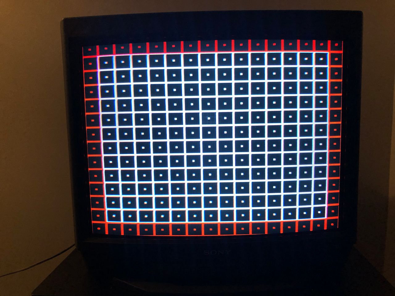
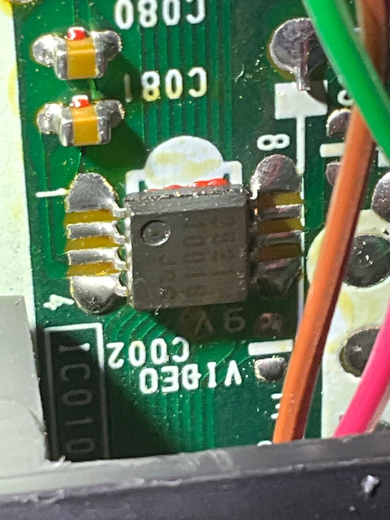
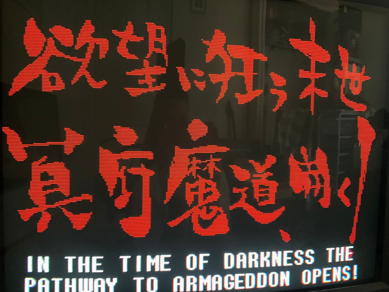
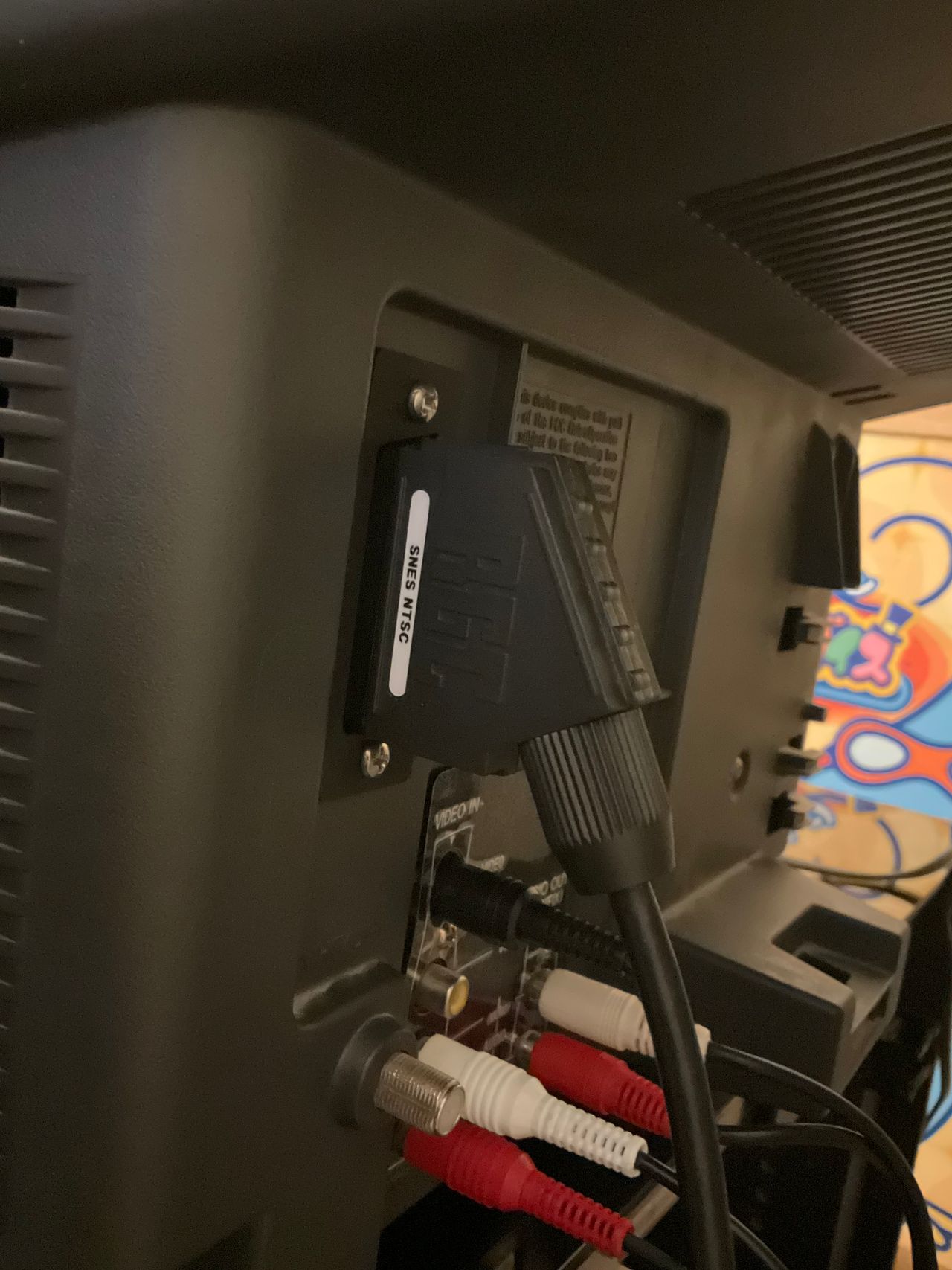
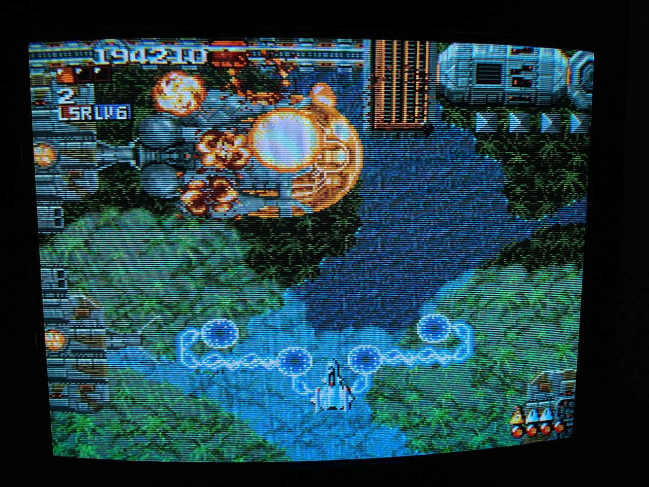
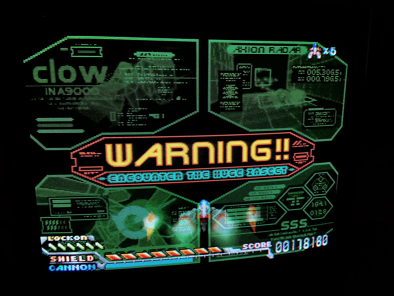
Some Sony KV-27S42 CRT televisions may exhibit sync issues with certain consoles, including the Raspberry Pi, Nintendo 64, and Super Nintendo. This issue is typically found on later KV-27S42 revisions that use a specific sync-separation IC.
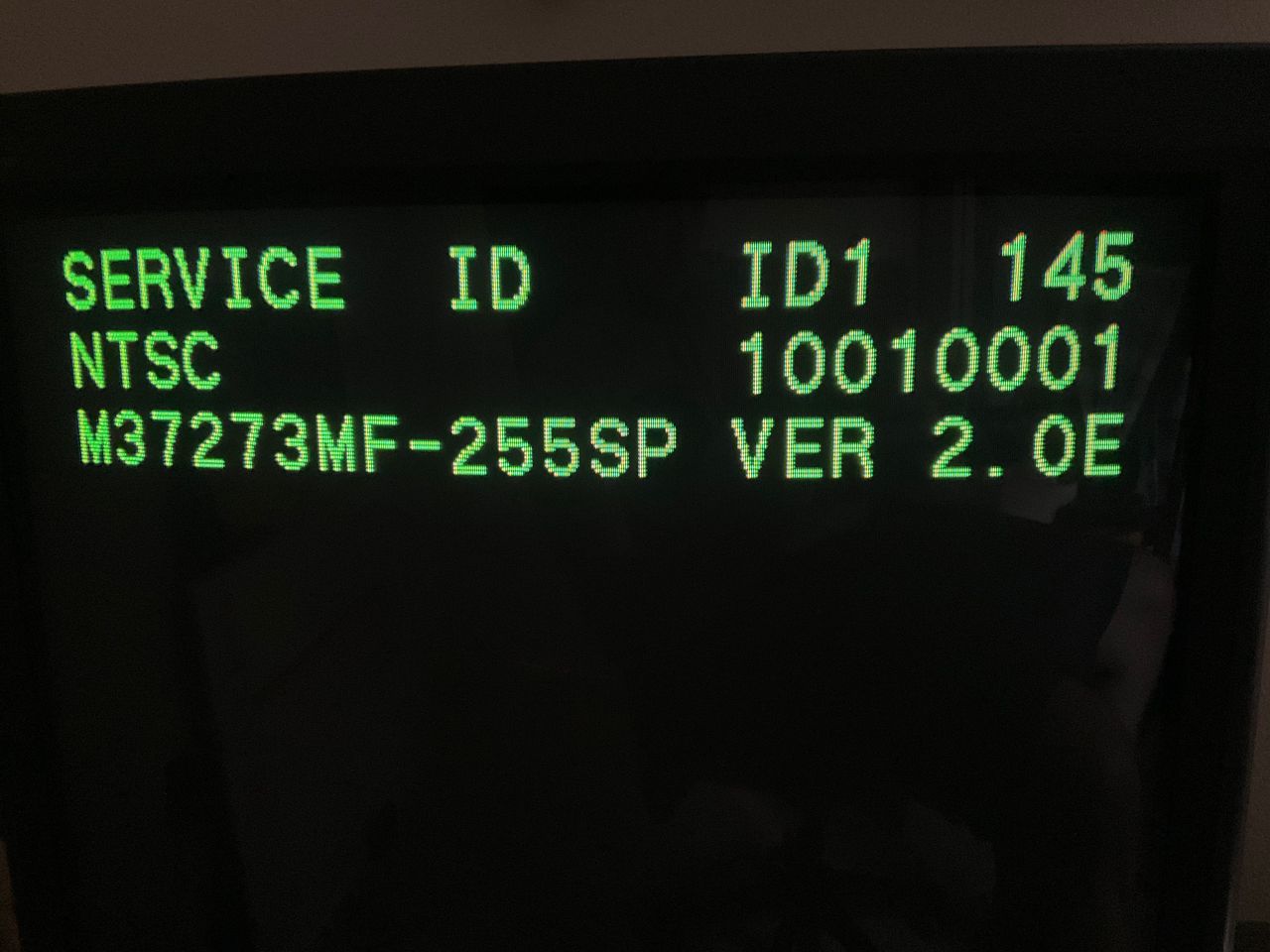
A workaround is to disable the sync-separation IC by changing the ID-1 value in the service menu from 145 to 23.
Credit goes to Kaz Packman for discovering this solution.
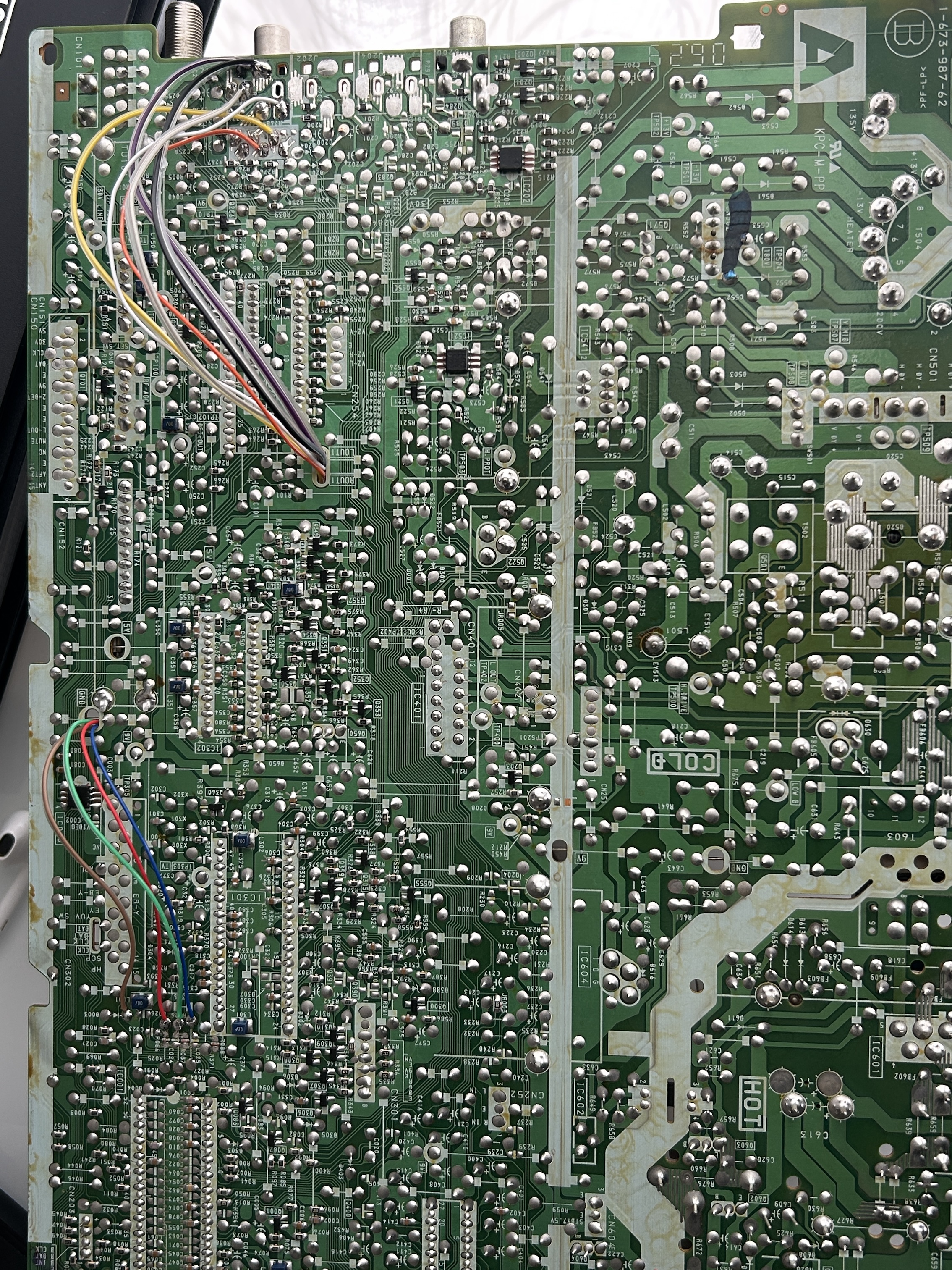
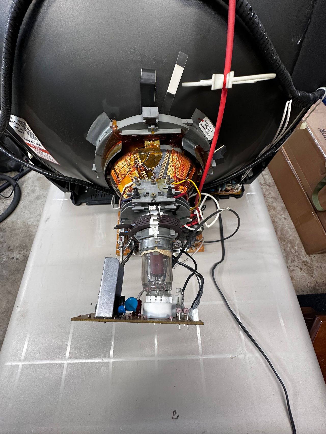
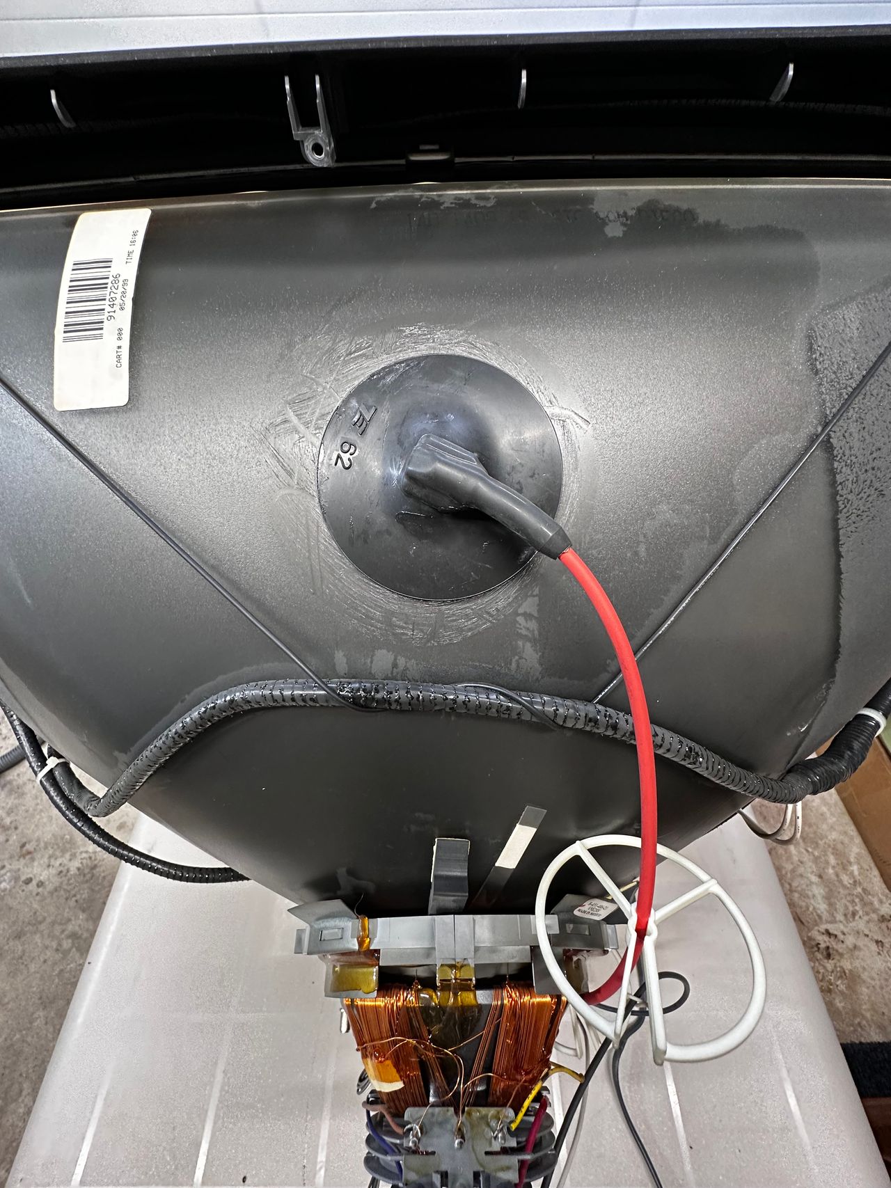
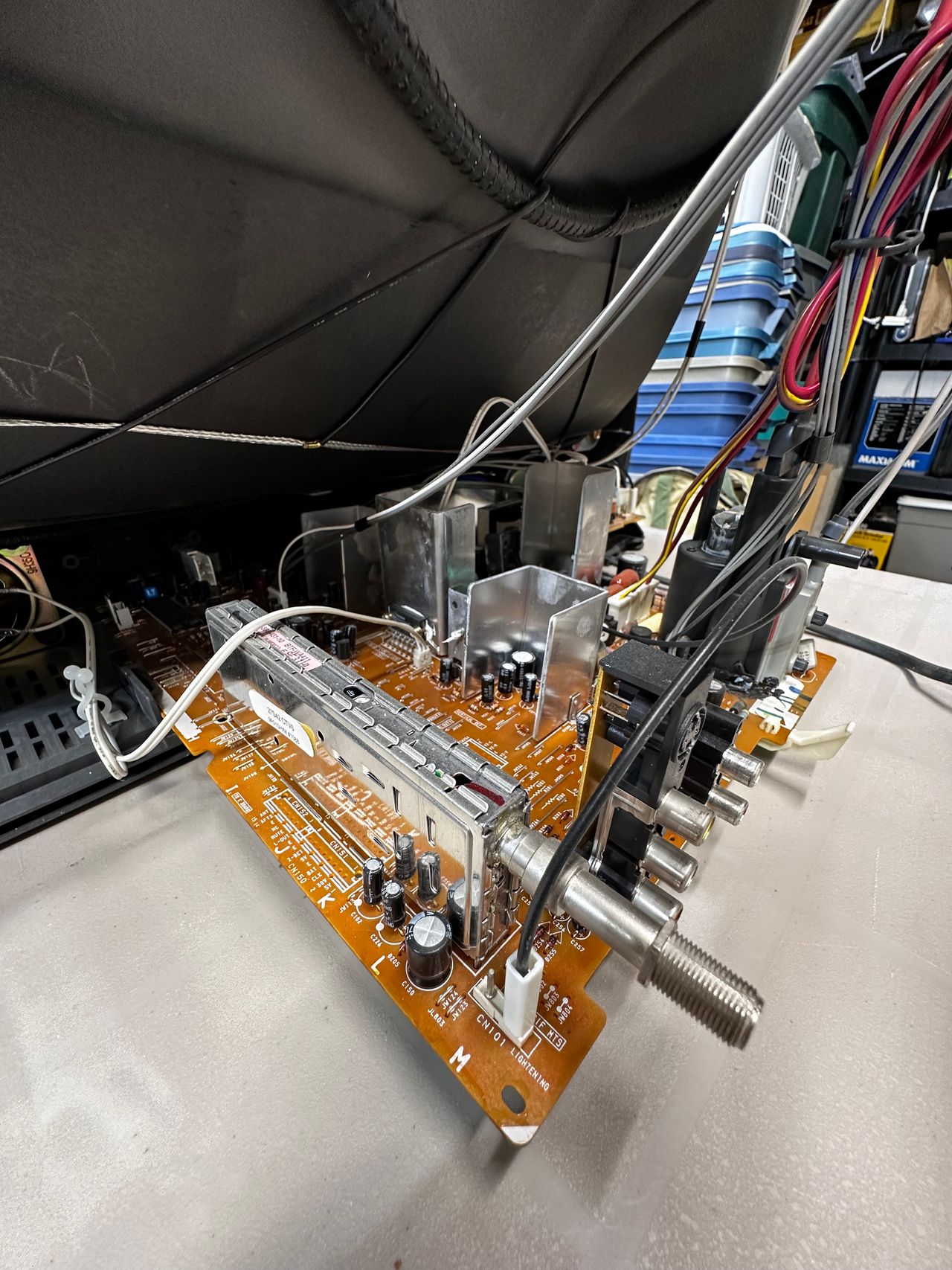
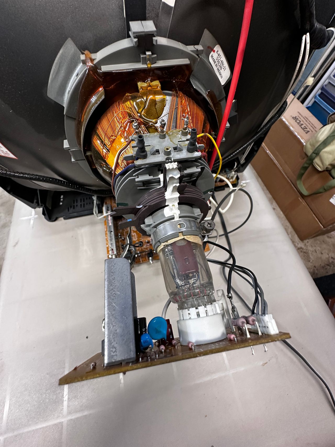
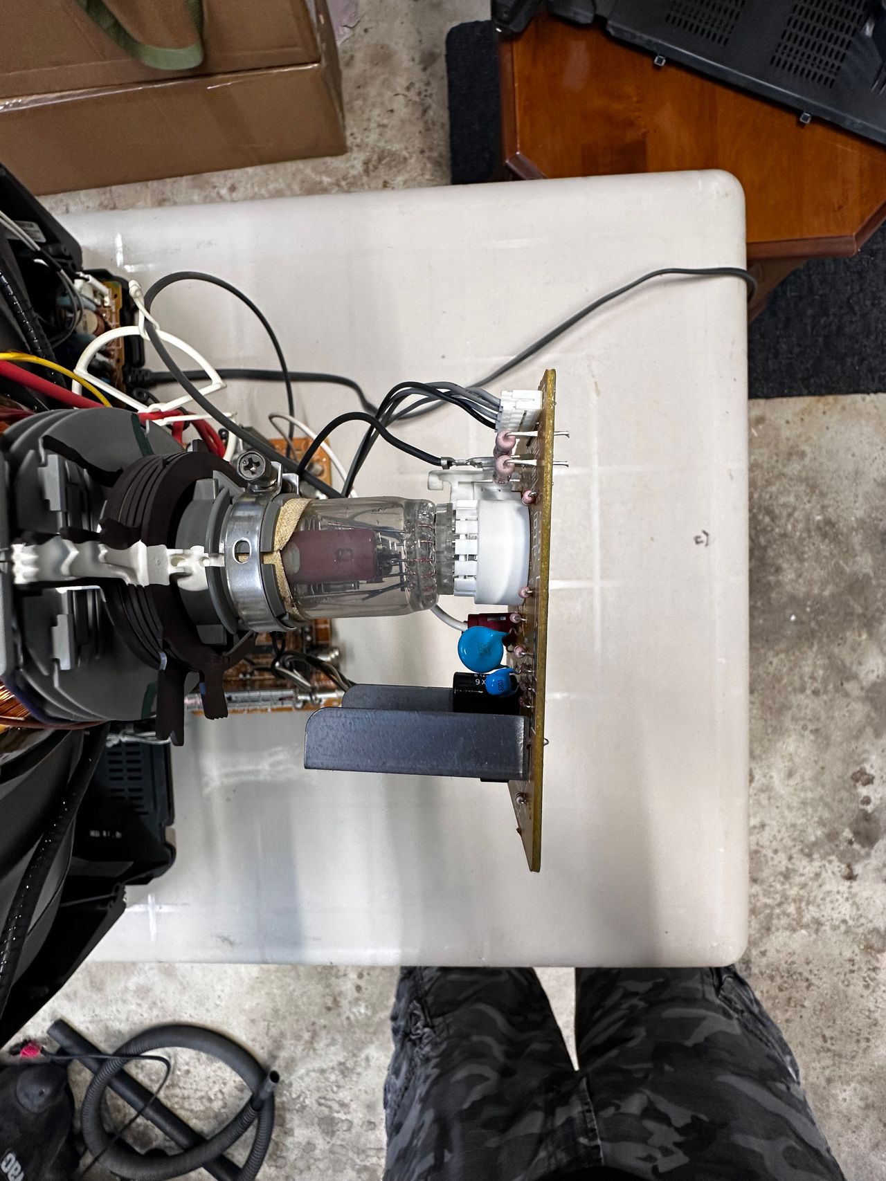
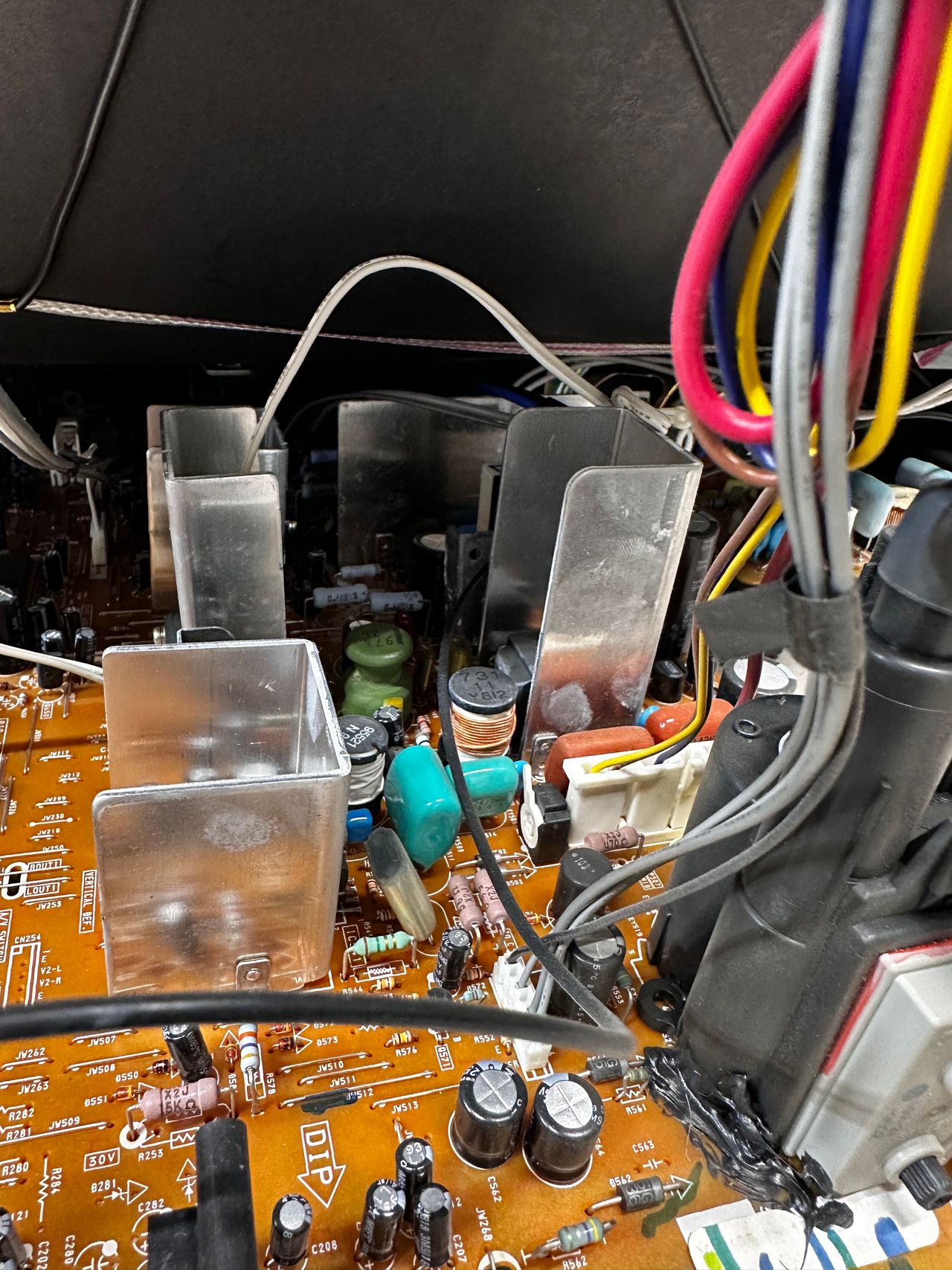
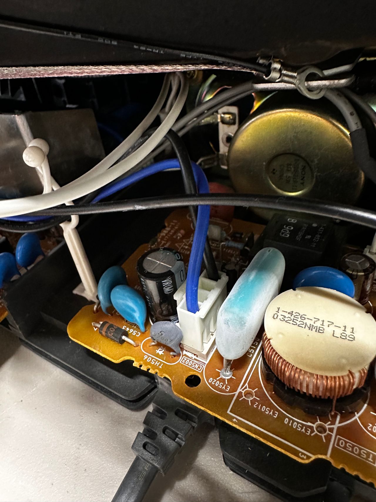
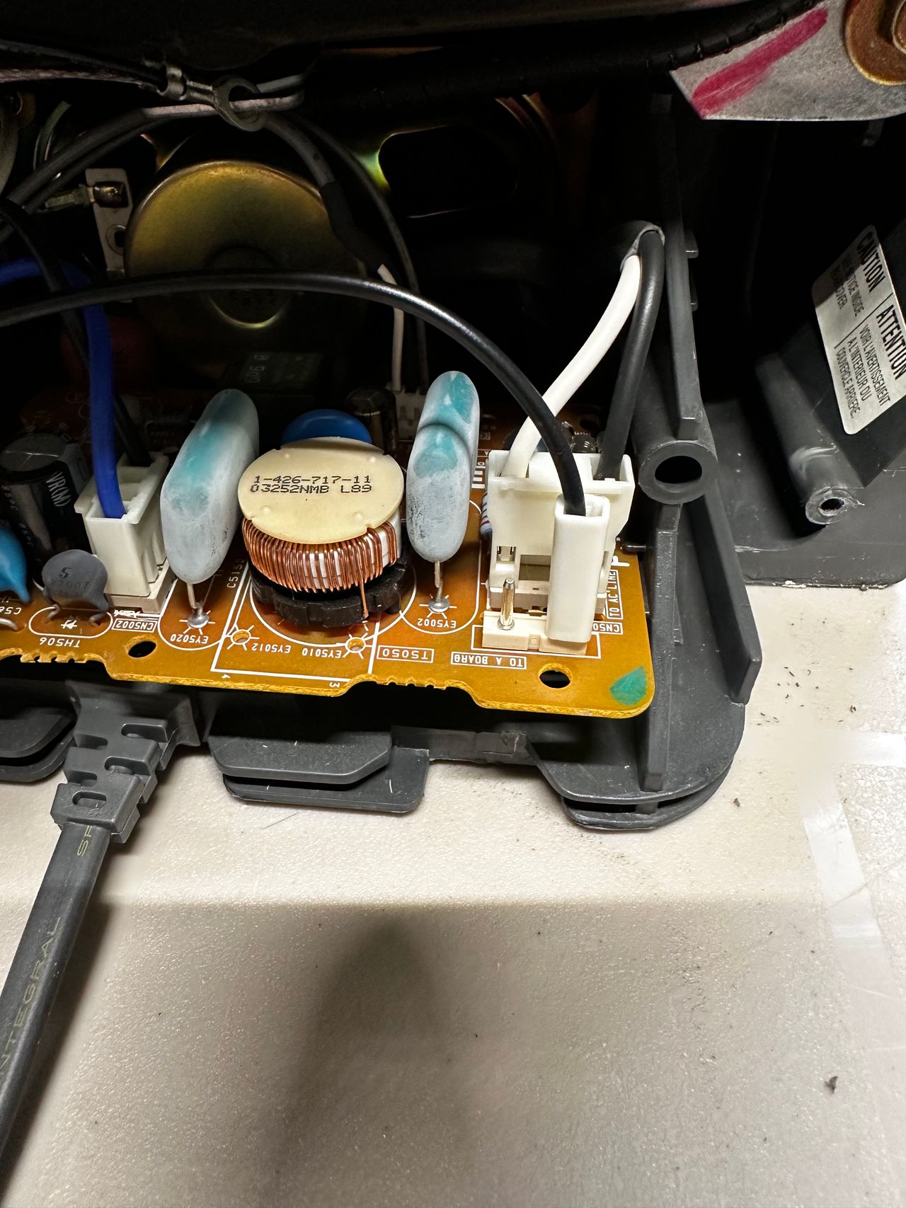
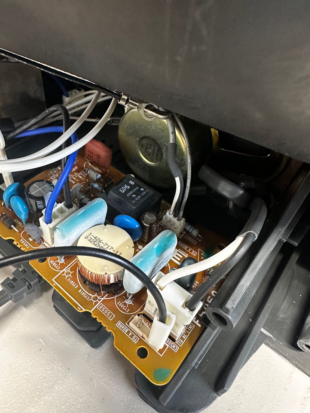
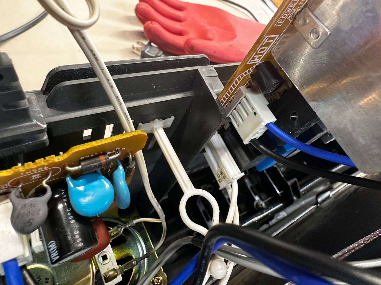
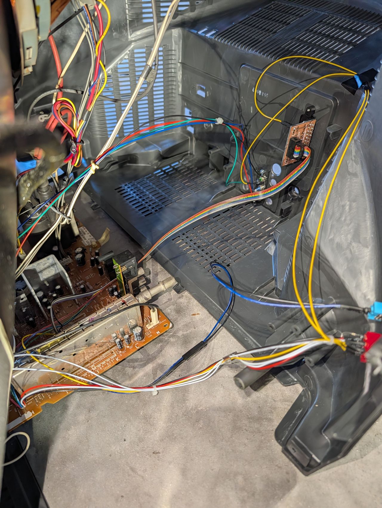
Additional Pictures
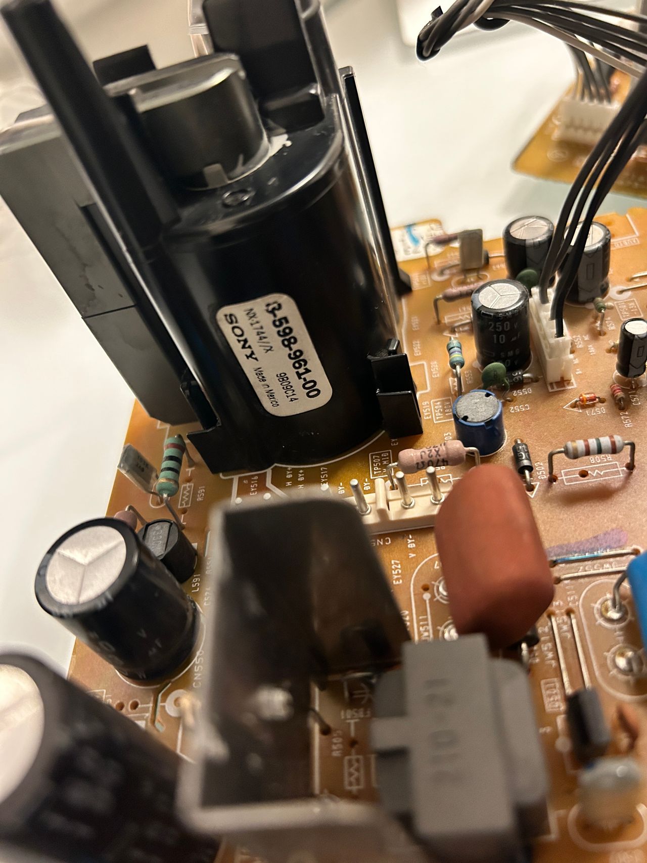
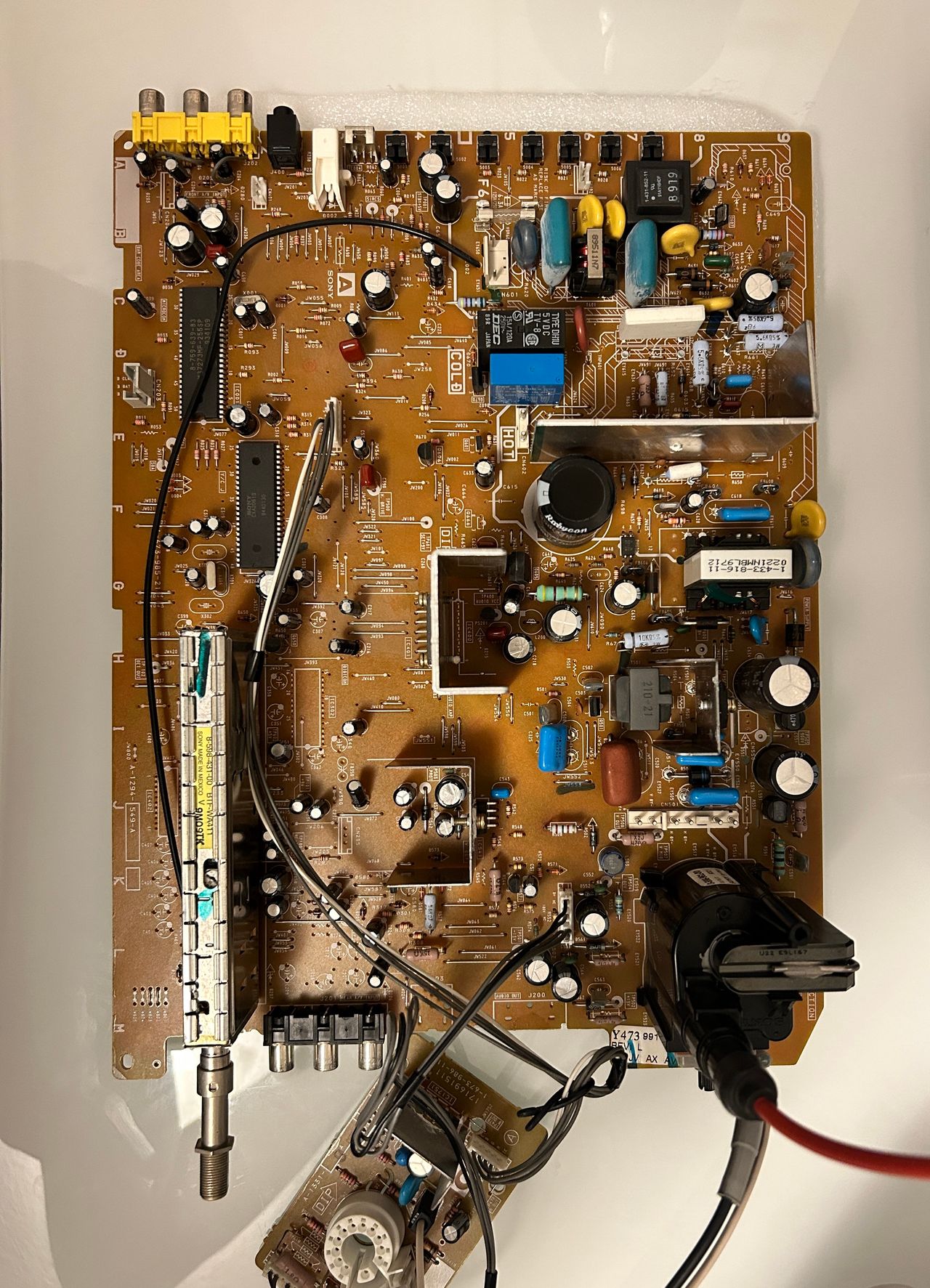
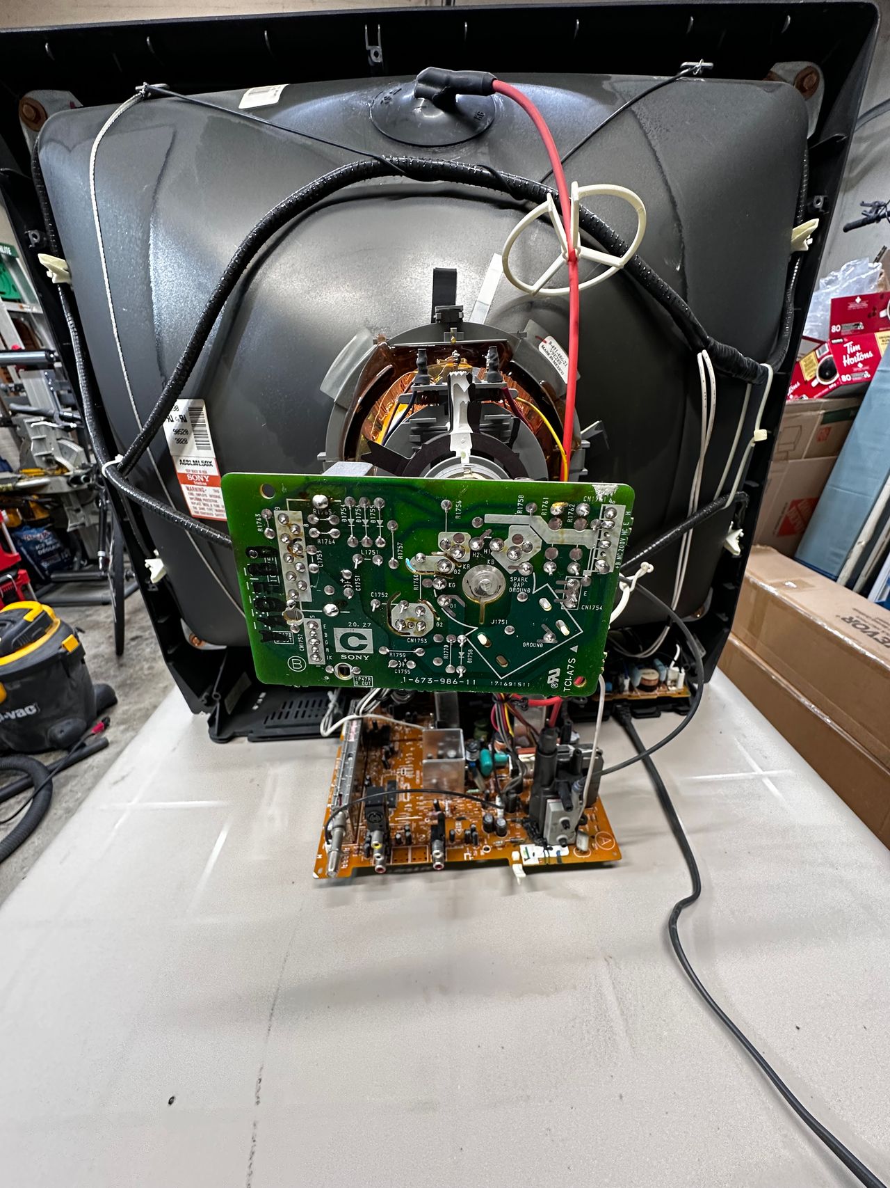
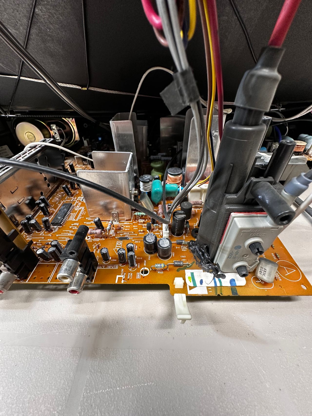
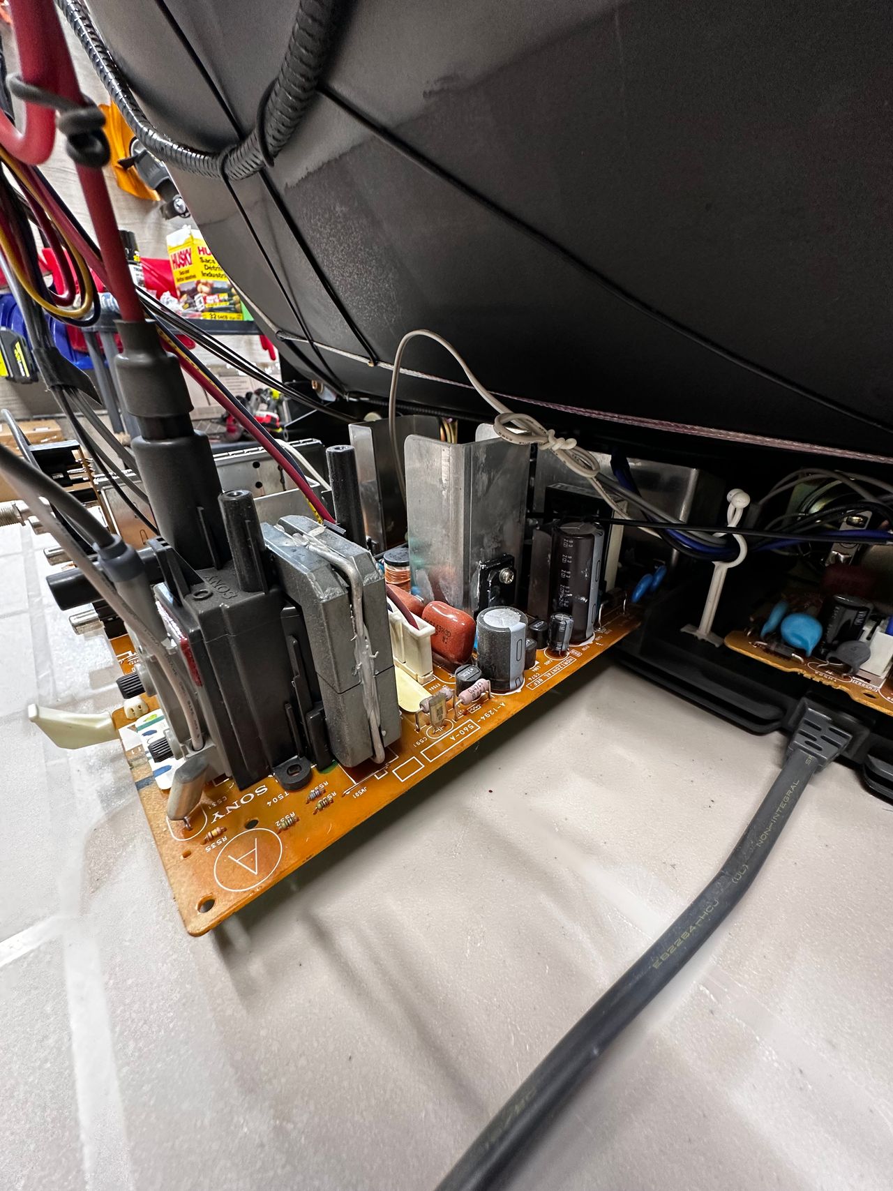
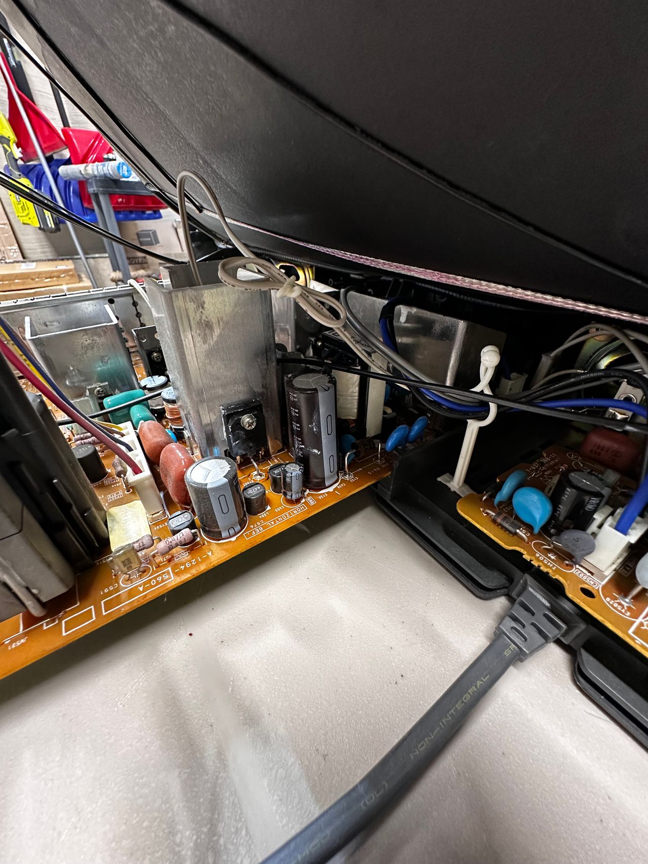
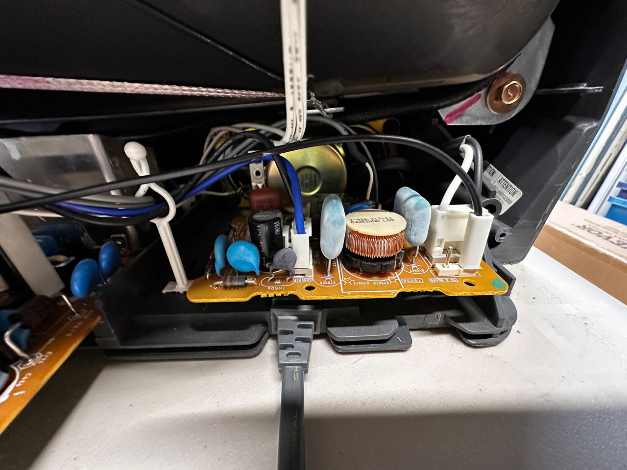
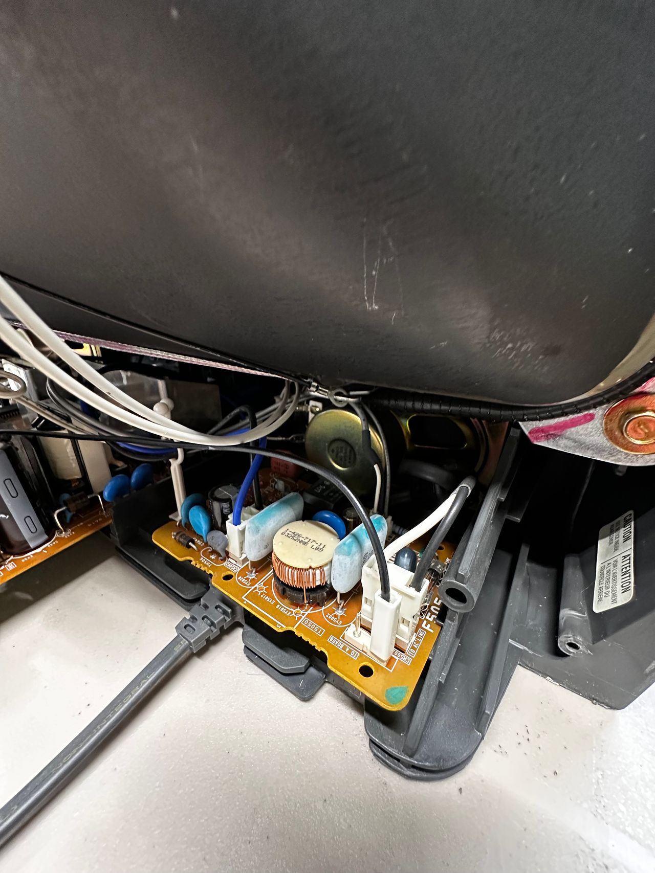
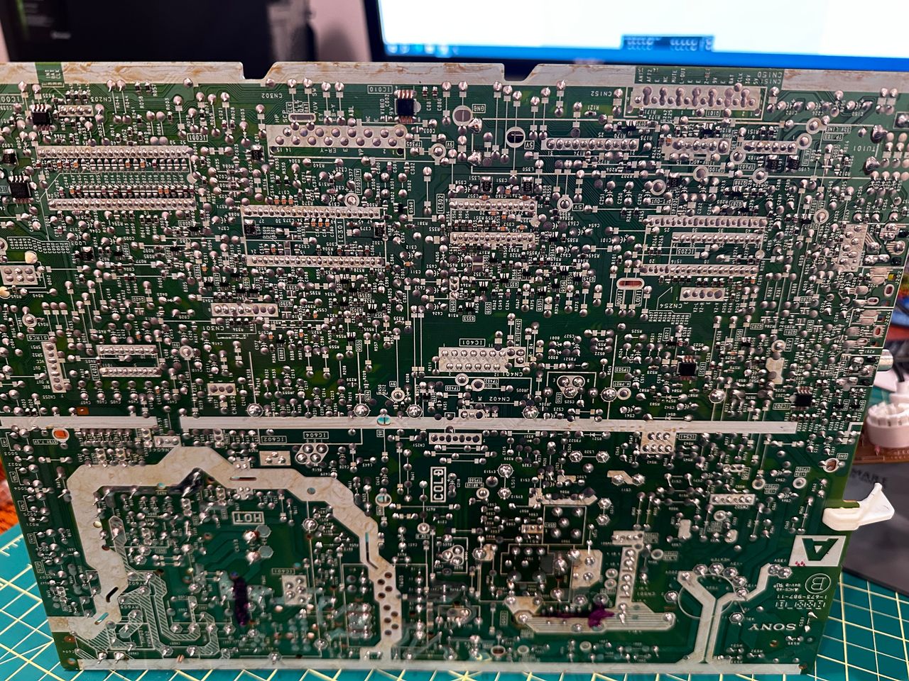
I had my boards loose during testing. Be extremely careful to avoid applying pressure on the chassis or accidentally touching the power board. 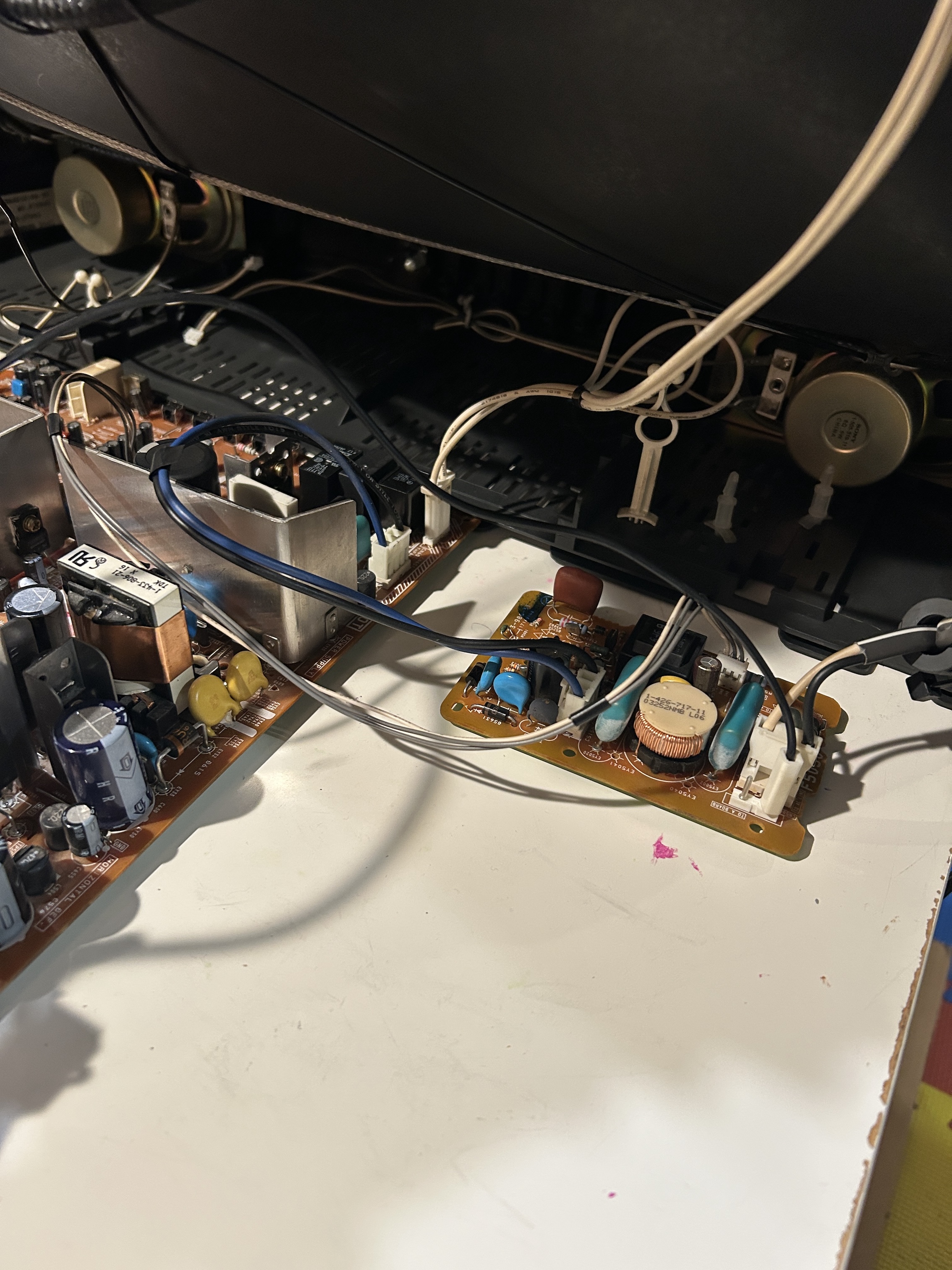
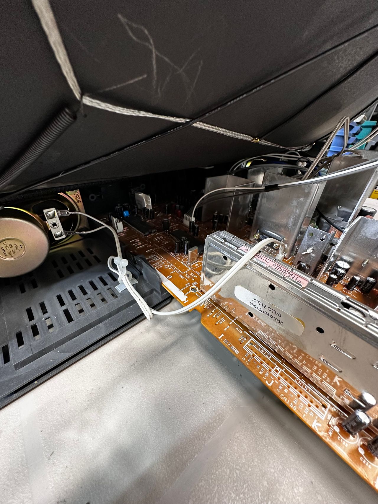
Pictures
Mod Photos
Sony KV-27S42 RGB Mod. LMUX BOARD.

Photos by Nostalgia FX Workshop
Photos by ALttN
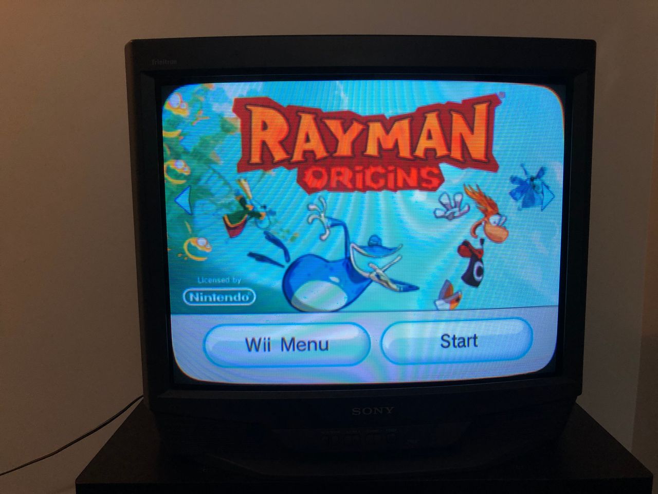
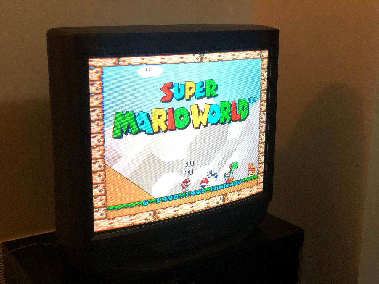
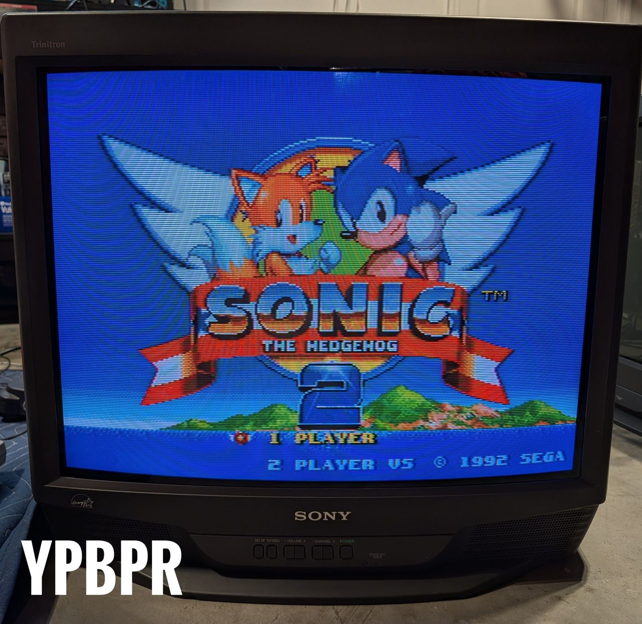
This Sony KV-27S42 CRT experienced sync issues with N64 and SNES. This was a later model KV-27S42, that used a specific IC for sync separation. This was disabled by changing the ID-1 value. Thanks to Kaz Packman for finding this solution.
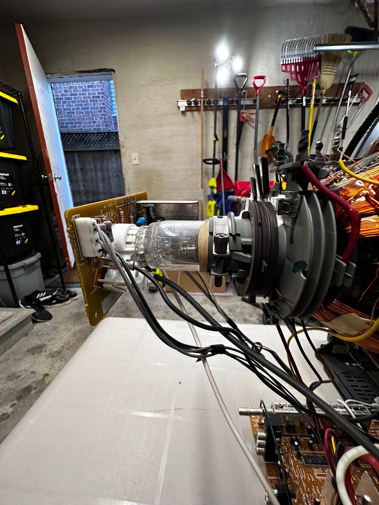
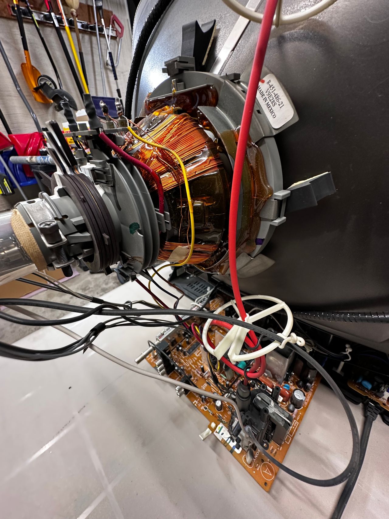
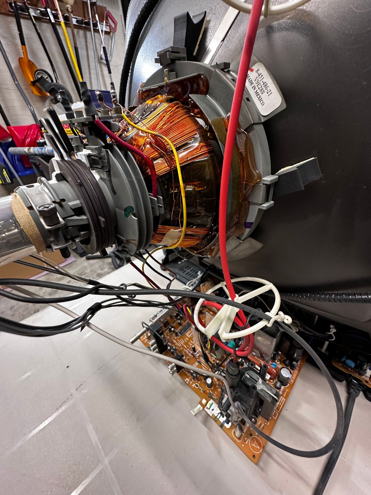
Reference Photos