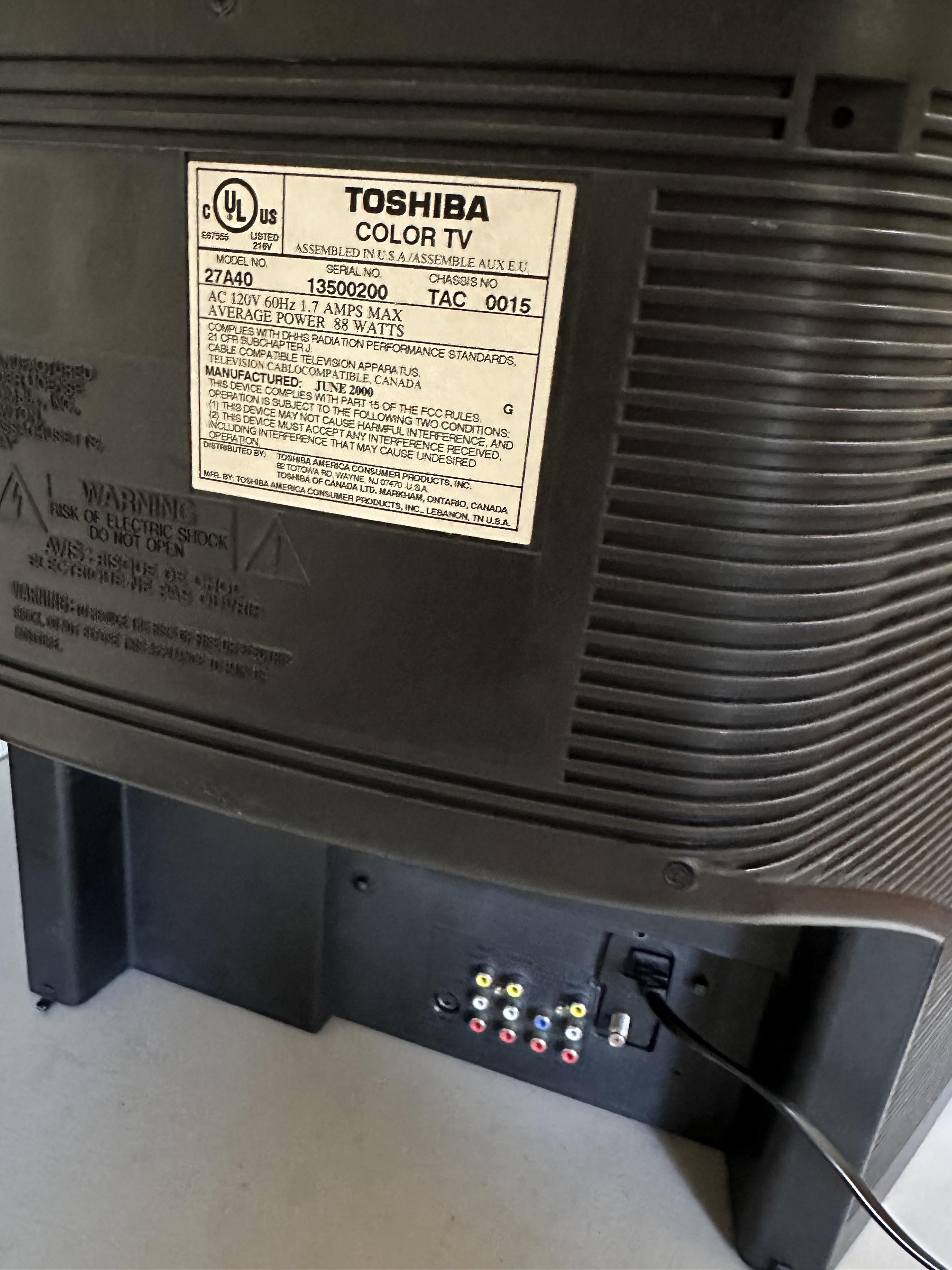
Toshiba 27A40
Toshiba 27A40 CRT RGB mod
This set uses the Chroma similar to Toshiba 27A34, however the location of jumpers and resistors are all different.

CRT safety
Caution
You can die doing this! So read carefully! CRT TV is not a toy. Do not open a CRT TV. If you don't have any prior knowledge about handling high voltage devices, this guide is not for you. CRT TV contains high enough voltage (20,000+ V) and current to be deadly, even when it is turned off.
Plan of attack
Theory
Sometimes it is nice to know the theory behind the mod. I have put this on a separate page. This shows how the various resistor values are calculated.
Specs
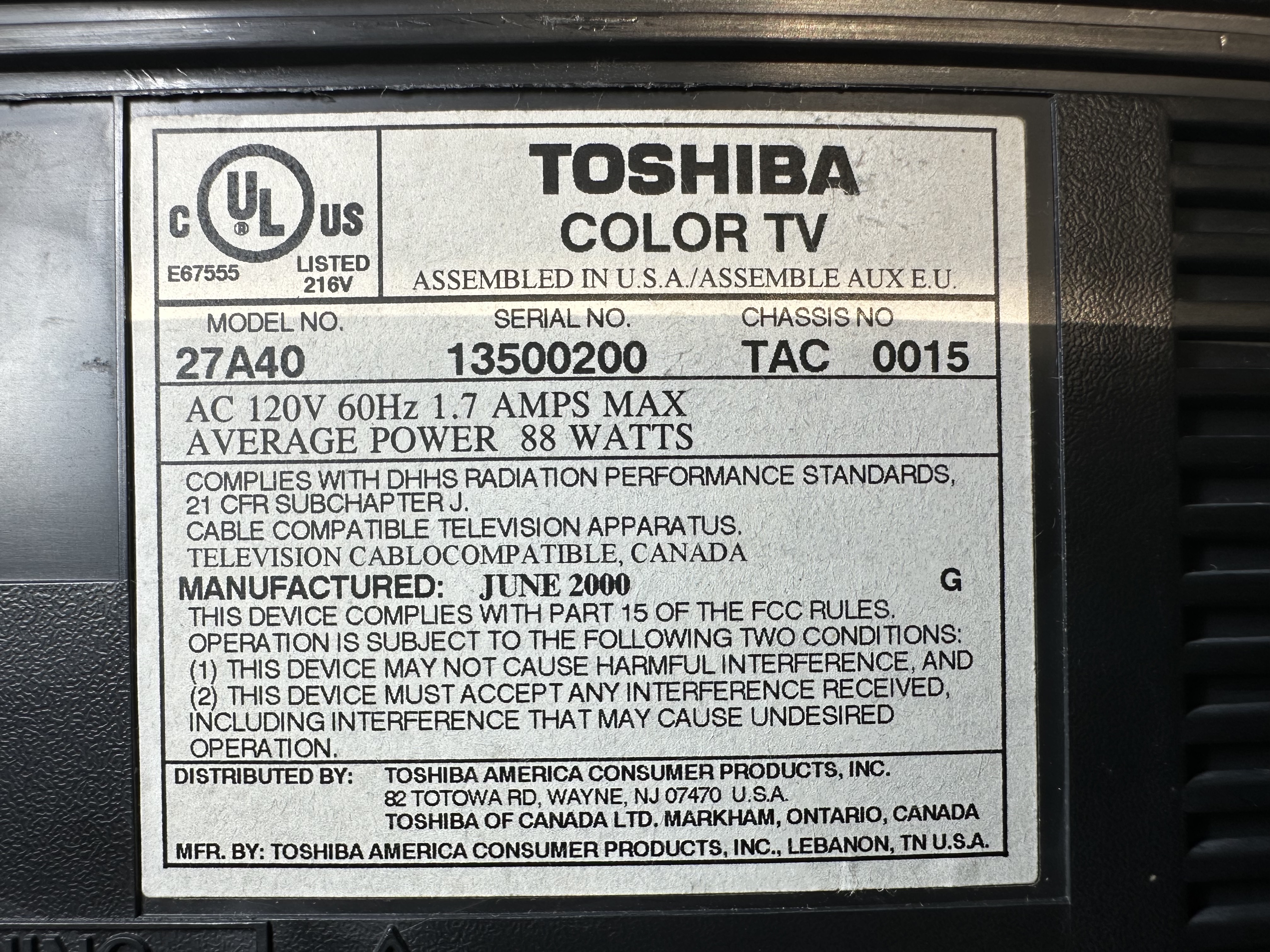
- Manufactured: Thailand, June 2000
- Power Consumption: 88W, 120V, 60Hz (NTSC)
- Chassis: TAC 0015
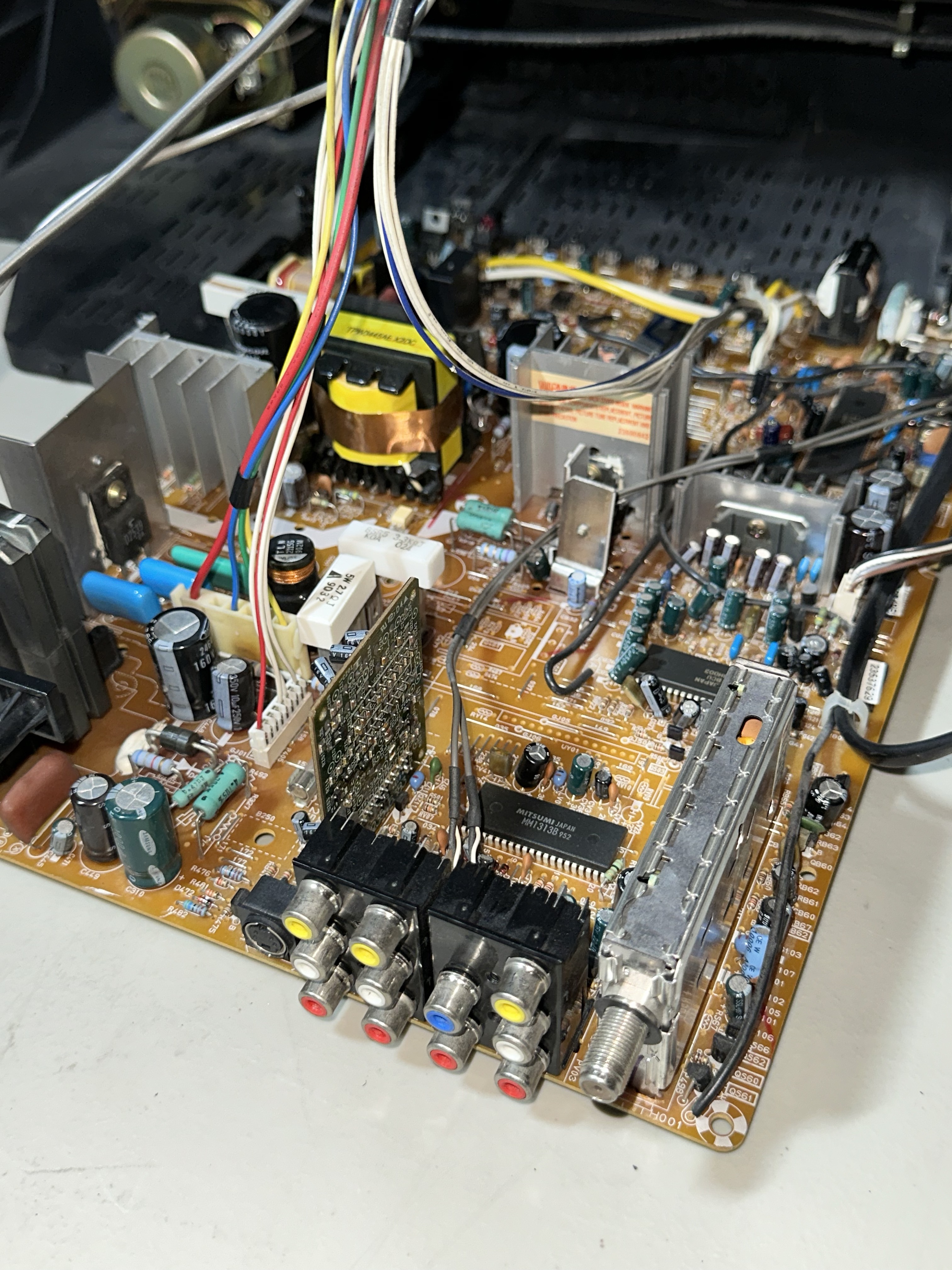
- Chroma: TA1310AN (Q501) (same chroma as the 27A34 model)
- OSD: TMPA8700CPN-1A05 (QA01)
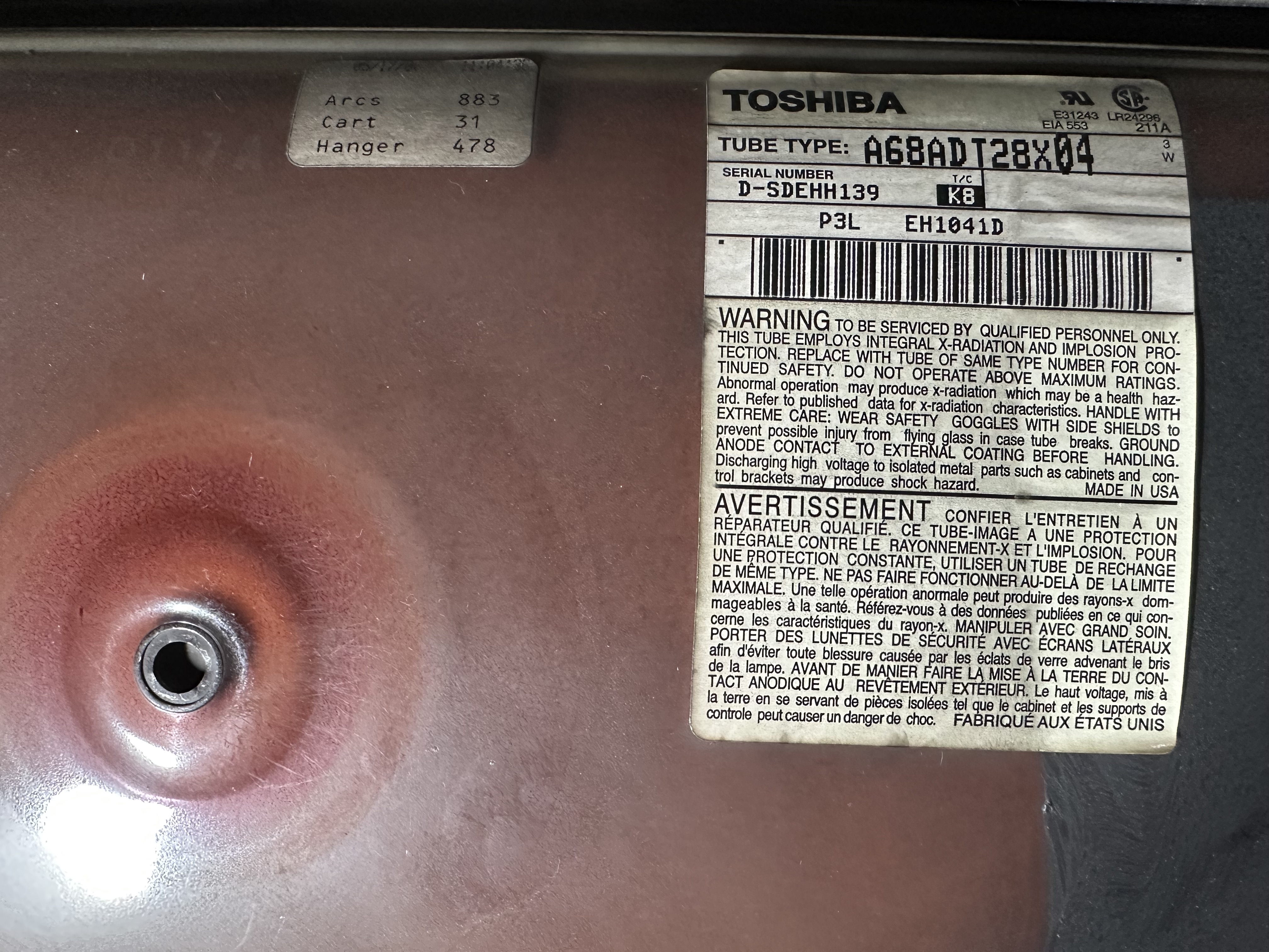
- Tube: Toshiba A68ADT28X04 Tube
Service manuals & Datasheets
Chassis
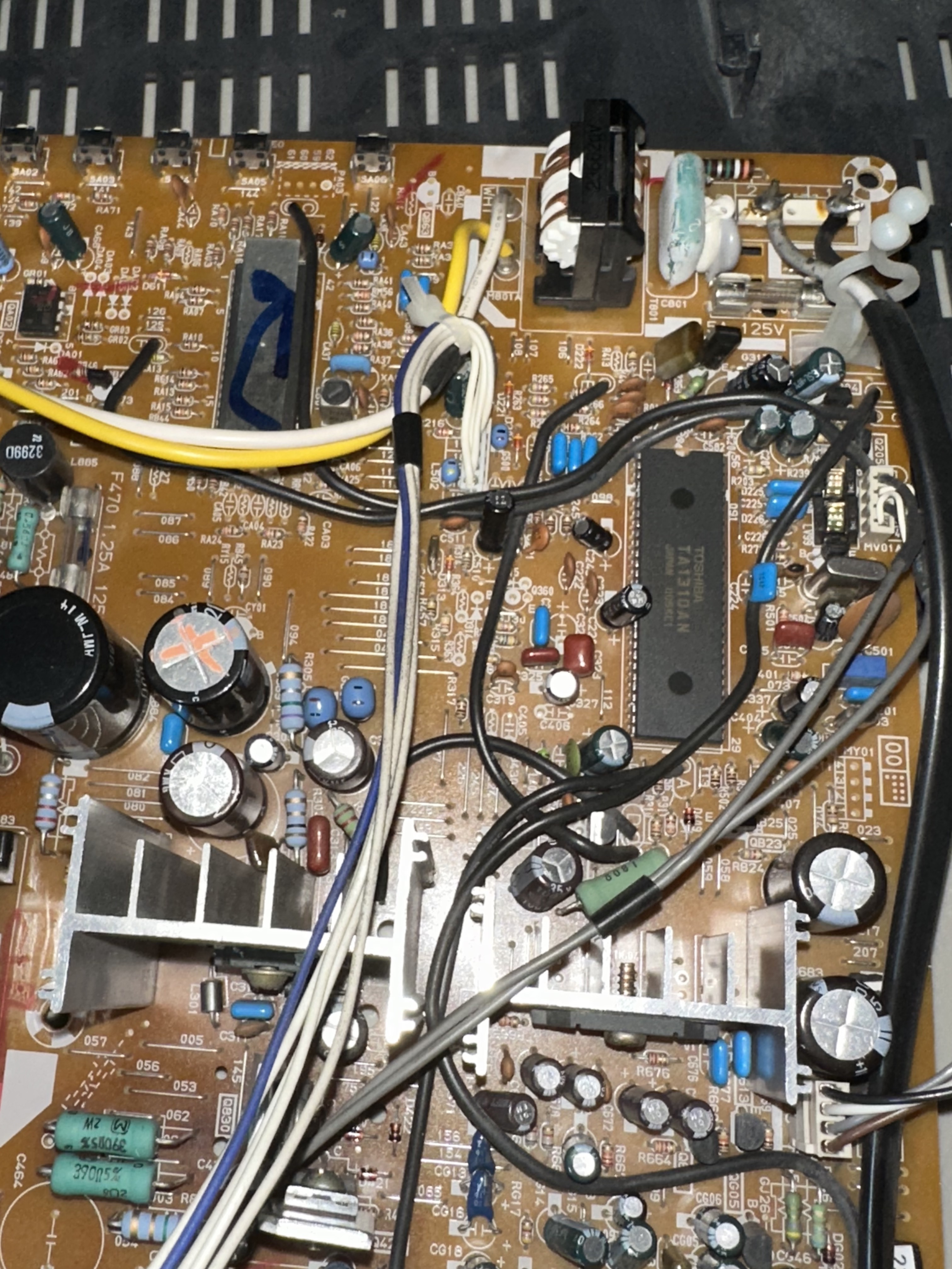
Mux Diagram
Get hold of the schematics/service manuals for your TV. Understand where the RGB and Fast Blanking signals go from OSD to the Jungle (Chroma) chip.
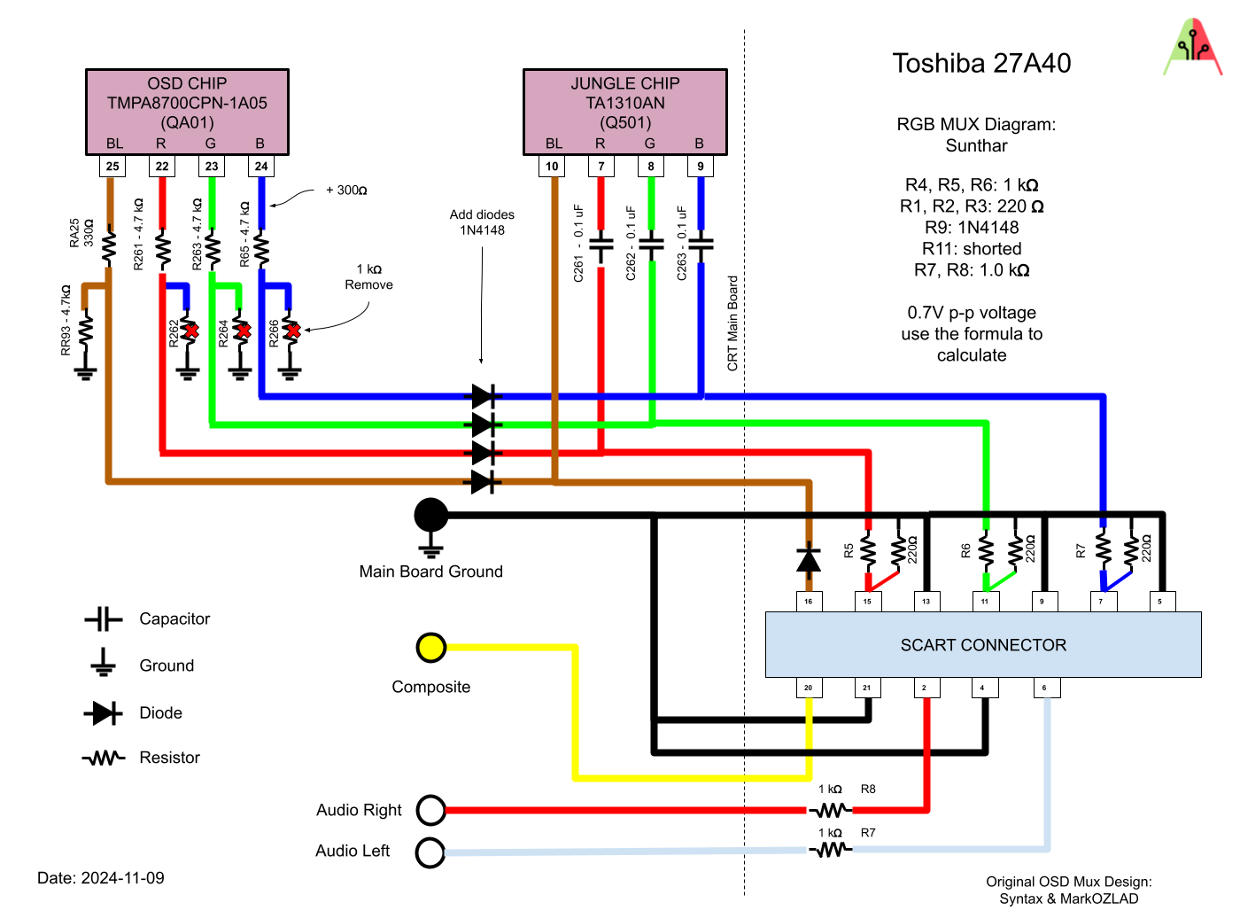
STEP 1: Remove the grounding resistors and capacitors
We are going to remove the three 1kΩ RGB ground resistors.
Remove
- R262 (1kΩ)
- R264 (1kΩ)
- R266 (1kΩ)
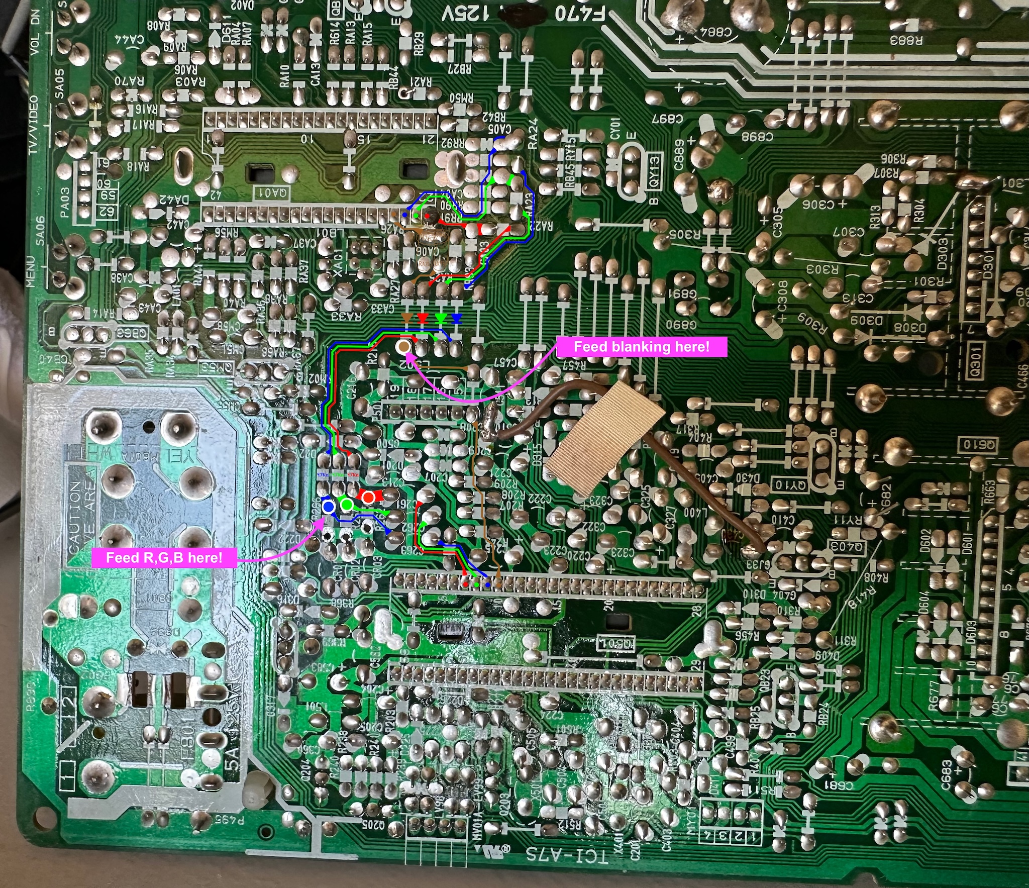
STEP 2: Connect RGB and blanking wires
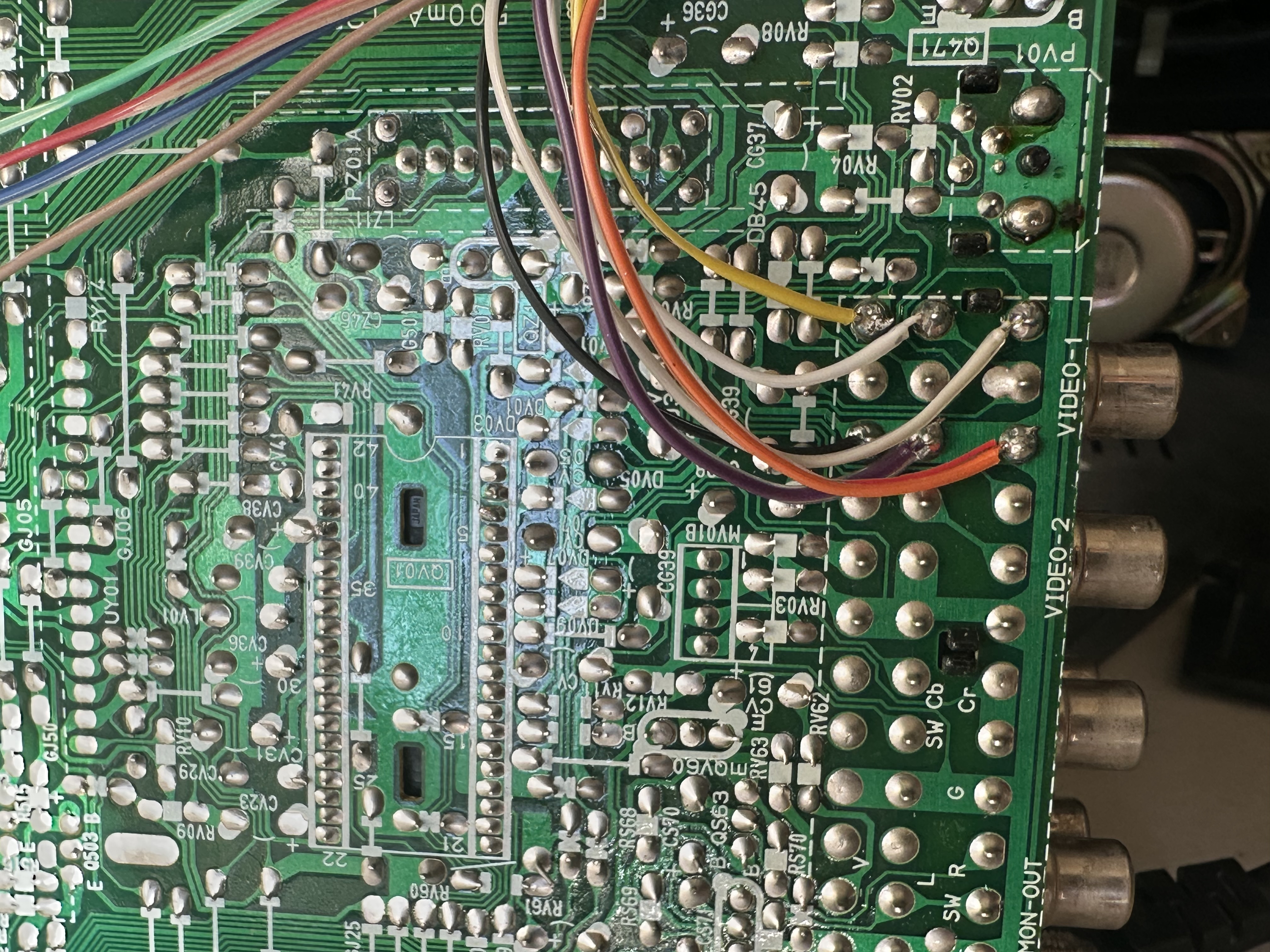
STEP 3: Connect sync, ground, and audio
STEP 4: Build your mux circuit
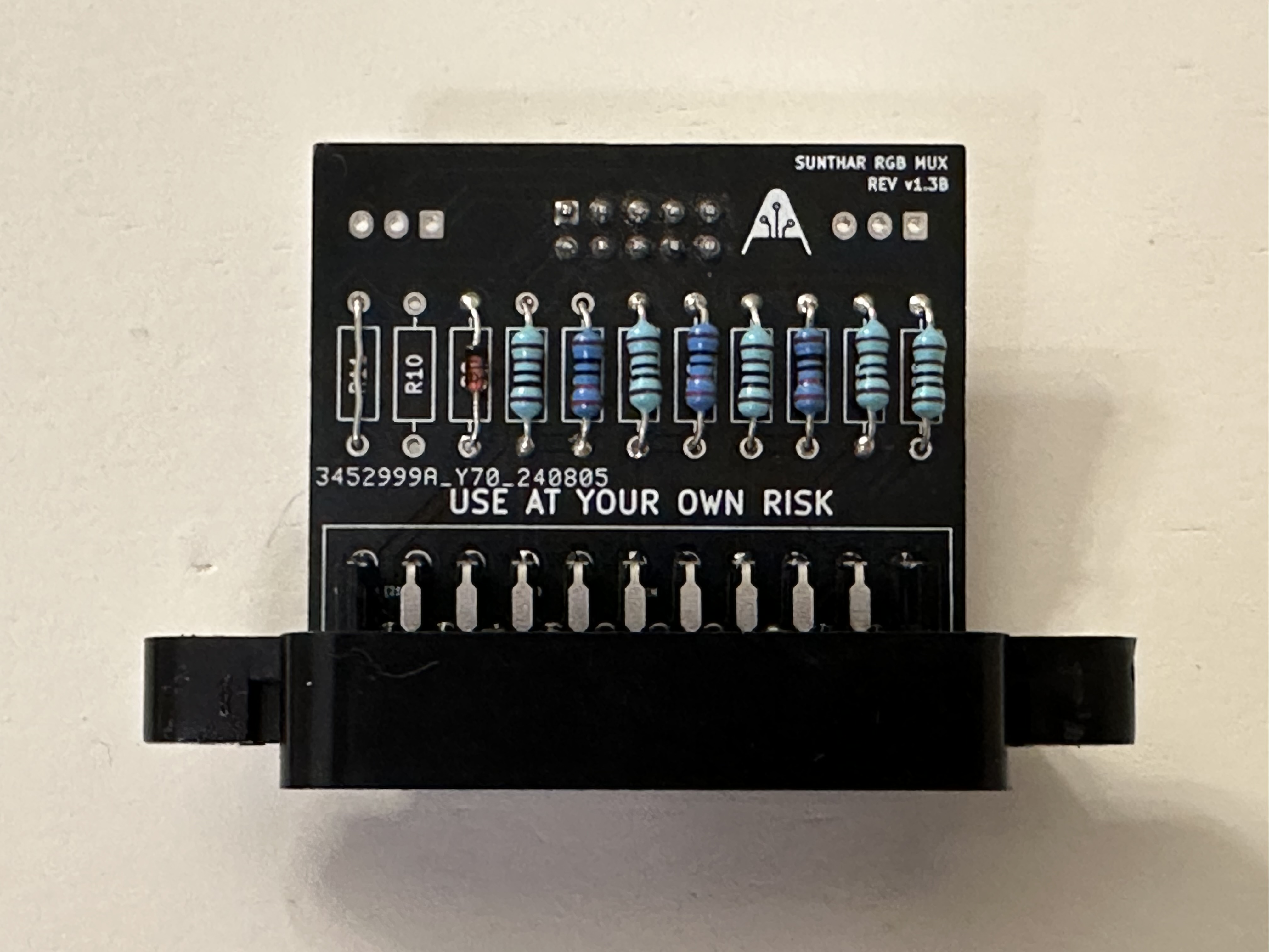
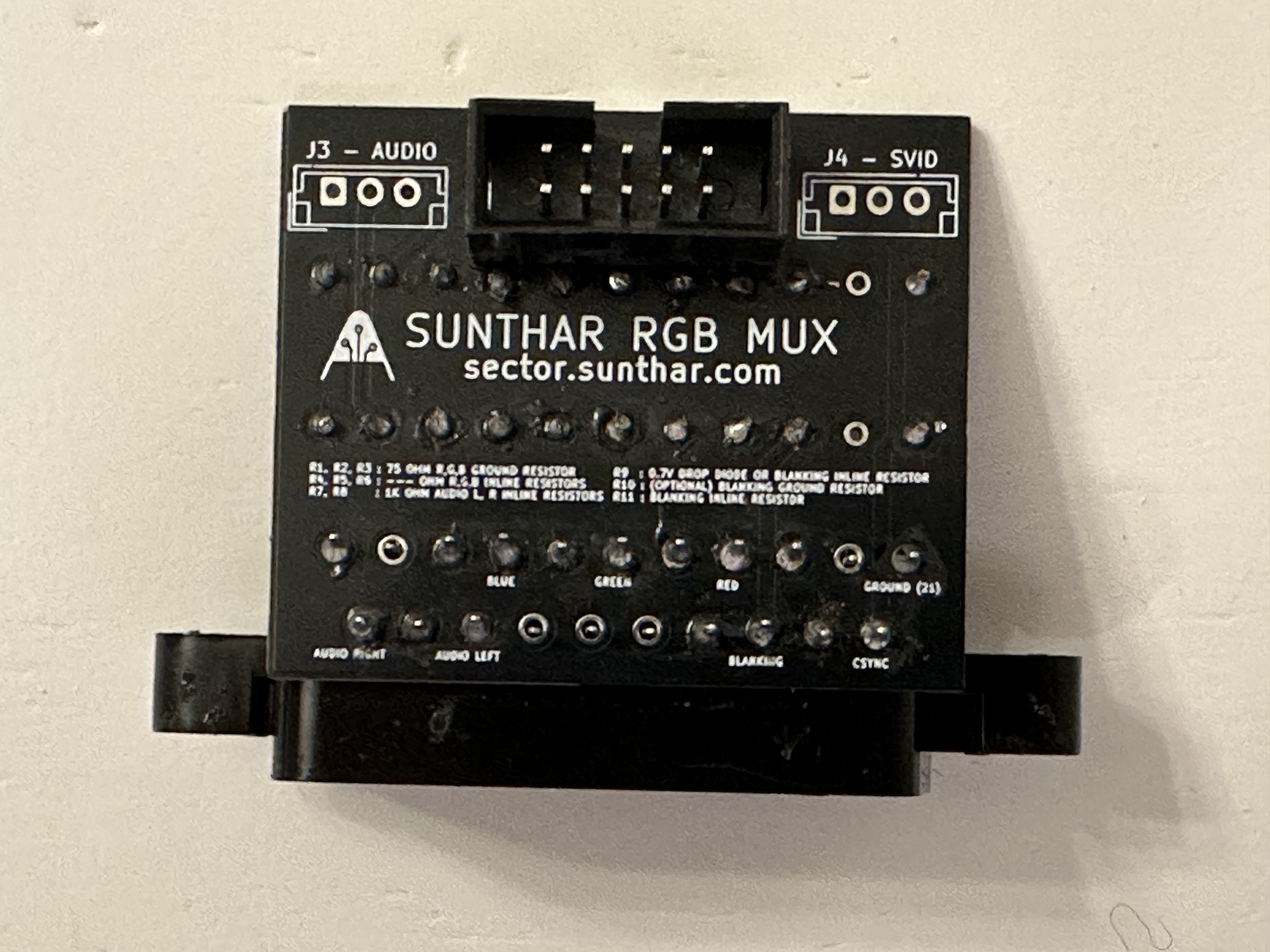
Below mod uses the RGB mux board. This is optional, but will make your mod easier and stable. You can also create the circuit presented in the schematics above without the board. Please also checkout the precalculated resistor values.
| Changes on the mux board | Toshiba 27A34 | Toshiba 27A40 |
|---|---|---|
| CRT RGB inline resistor (on chassis) | 3.9kΩ | 4.7kΩ |
| Removed resistor value (on chassis) | 820Ω | 1kΩ |
| Add blanking diode on chassis? | No | No |
| Add RGB diodes on chassis? | Yes | ? |
| RGB termination (R1, R2, R3) | 75Ω | 220Ω |
| RGB inline resistors (R4, R5, R6) | 750Ω | 1kΩ |
| Audio LR (R7, R8) | 1kΩ/shorted | 1kΩ/shorted |
| Diode (R9) | 1N4148 | 1N4148 |
| Blanking Ground Resistor (R10) | open | open |
| Blanking Resistor (R11) | shorted | shorted |
Warning
I'm often asked why a black and white image appears after an RGB mod. This issue occurs due to insufficient blanking voltage, which prevents the RGB chroma input from being enabled. What you're seeing in this case is the sync signal being sent to the luma input. To fix this, short R11 and leave the diode on R9. See the mux configuration above. Never exceed 5V with blanking - you will fry the chroma IC.
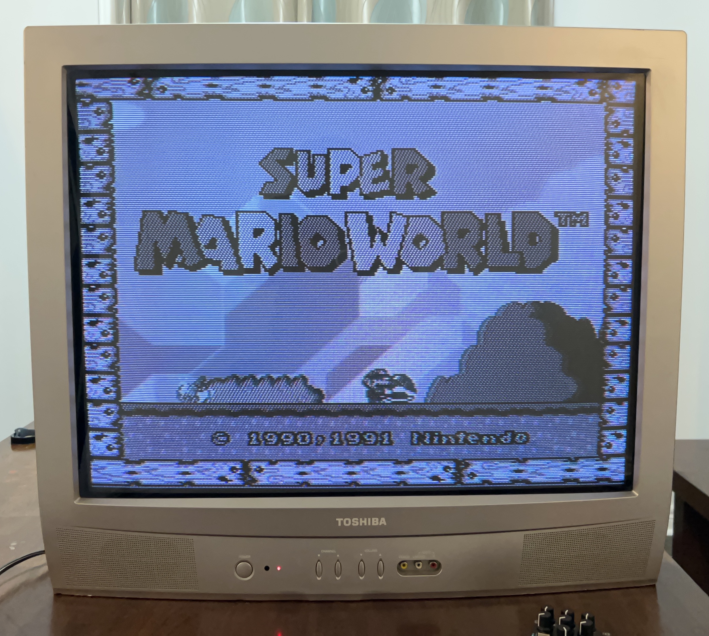
In the above image R9 had the diode and R11 had 1 kΩ resistor. I was able to test this with the RGB tuner.
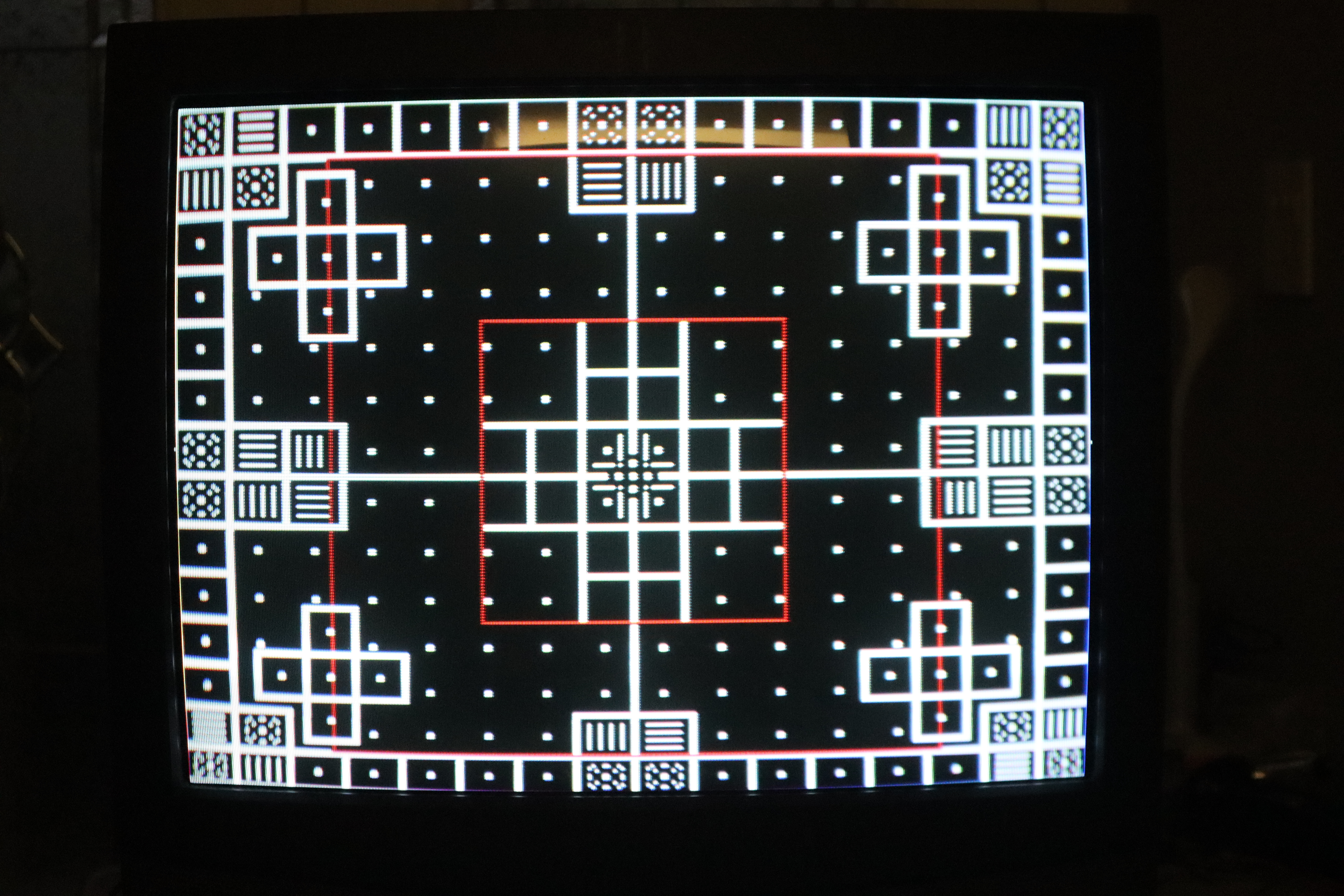
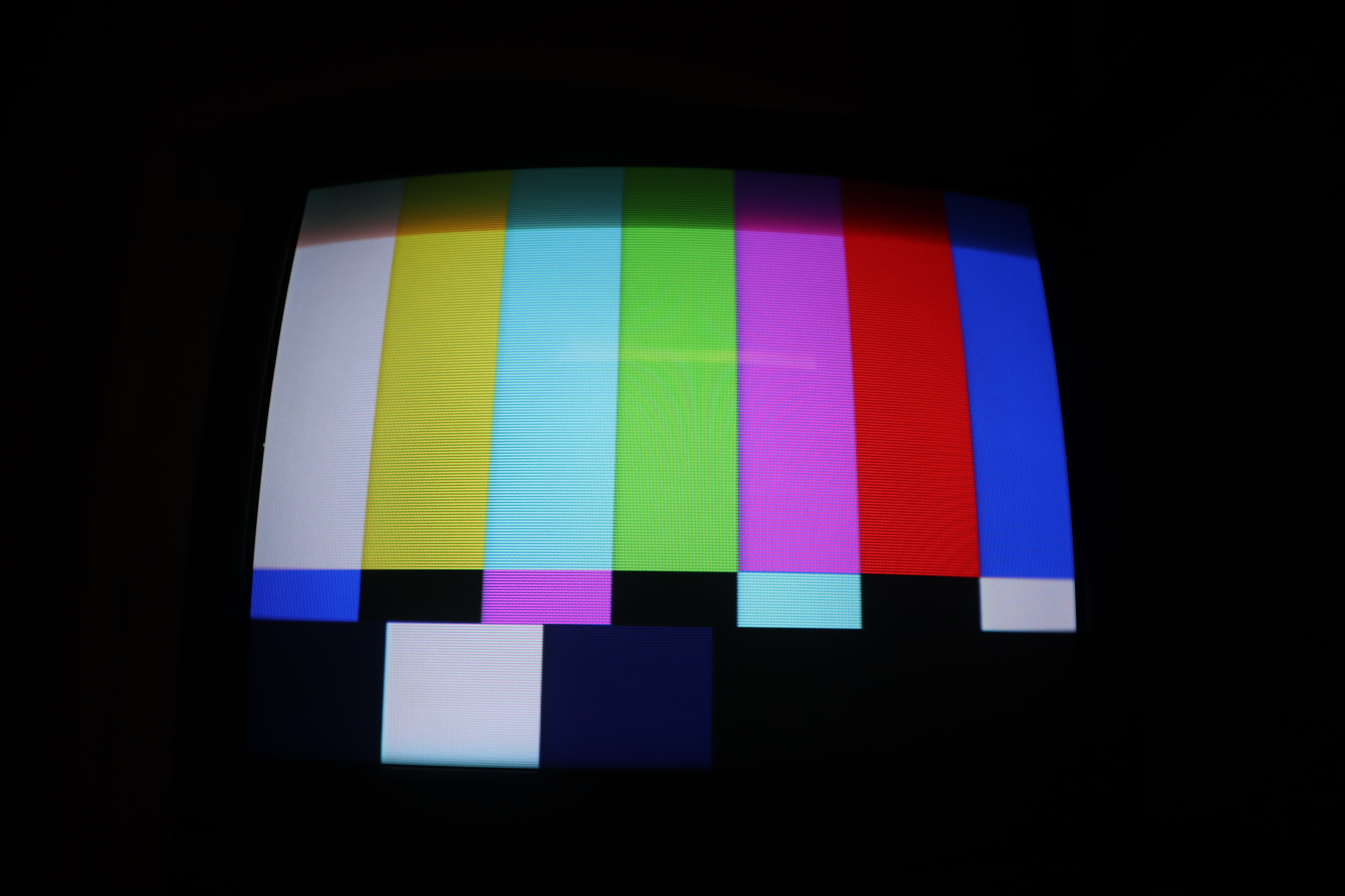
Pictures
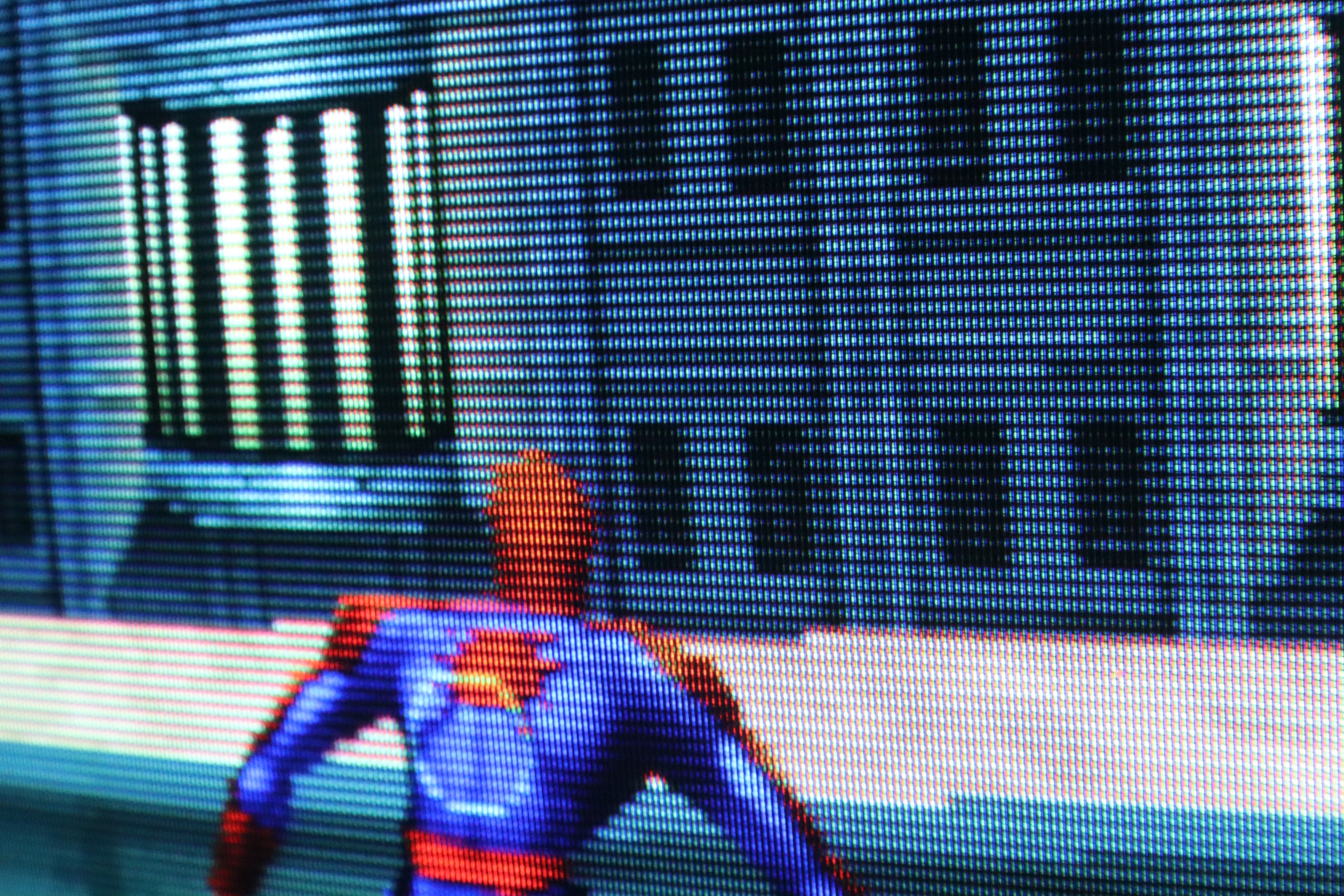
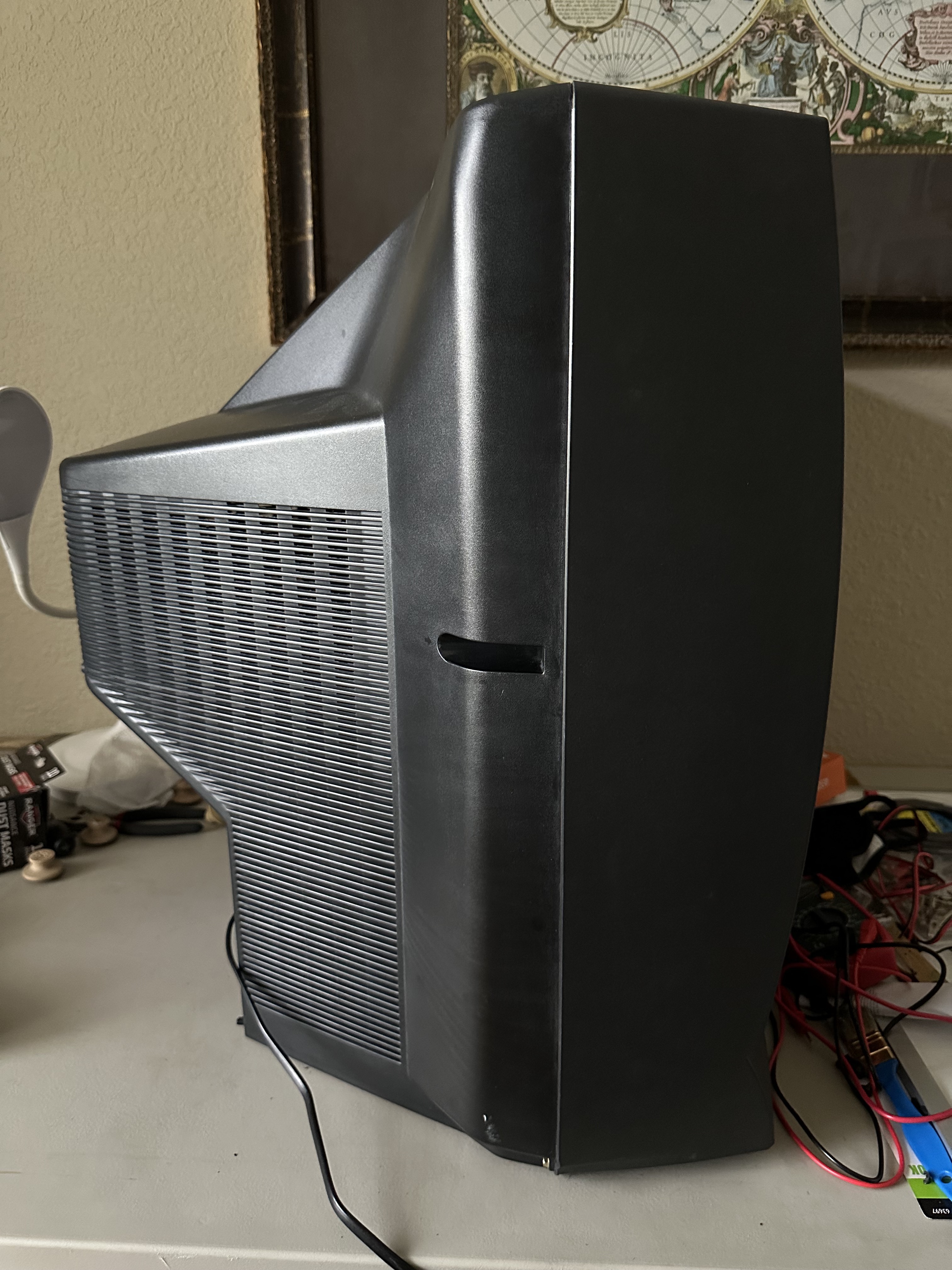
Set
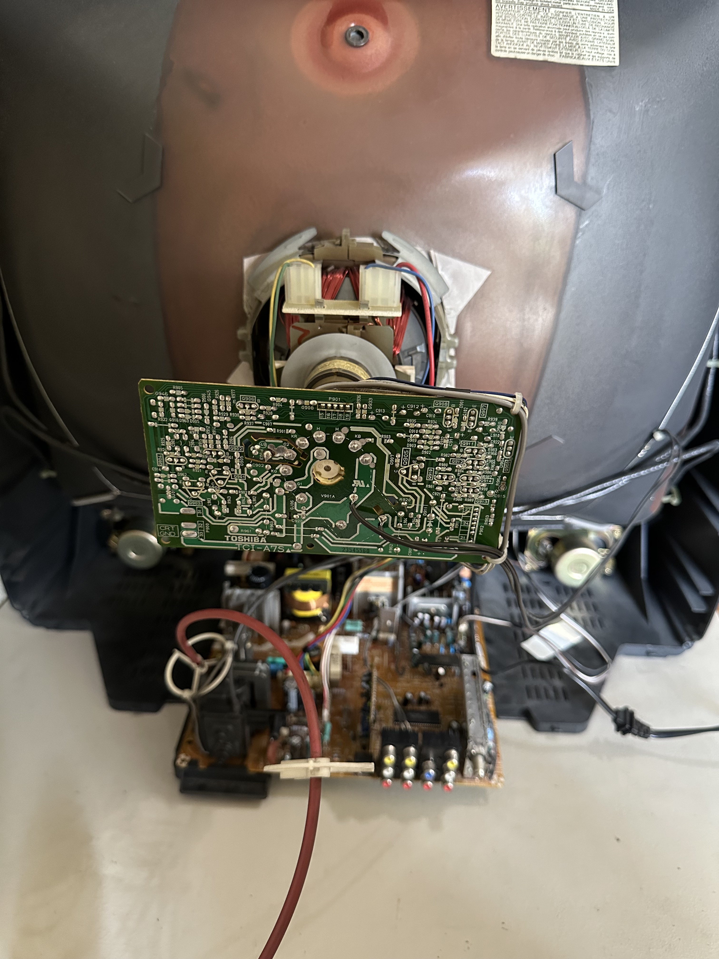
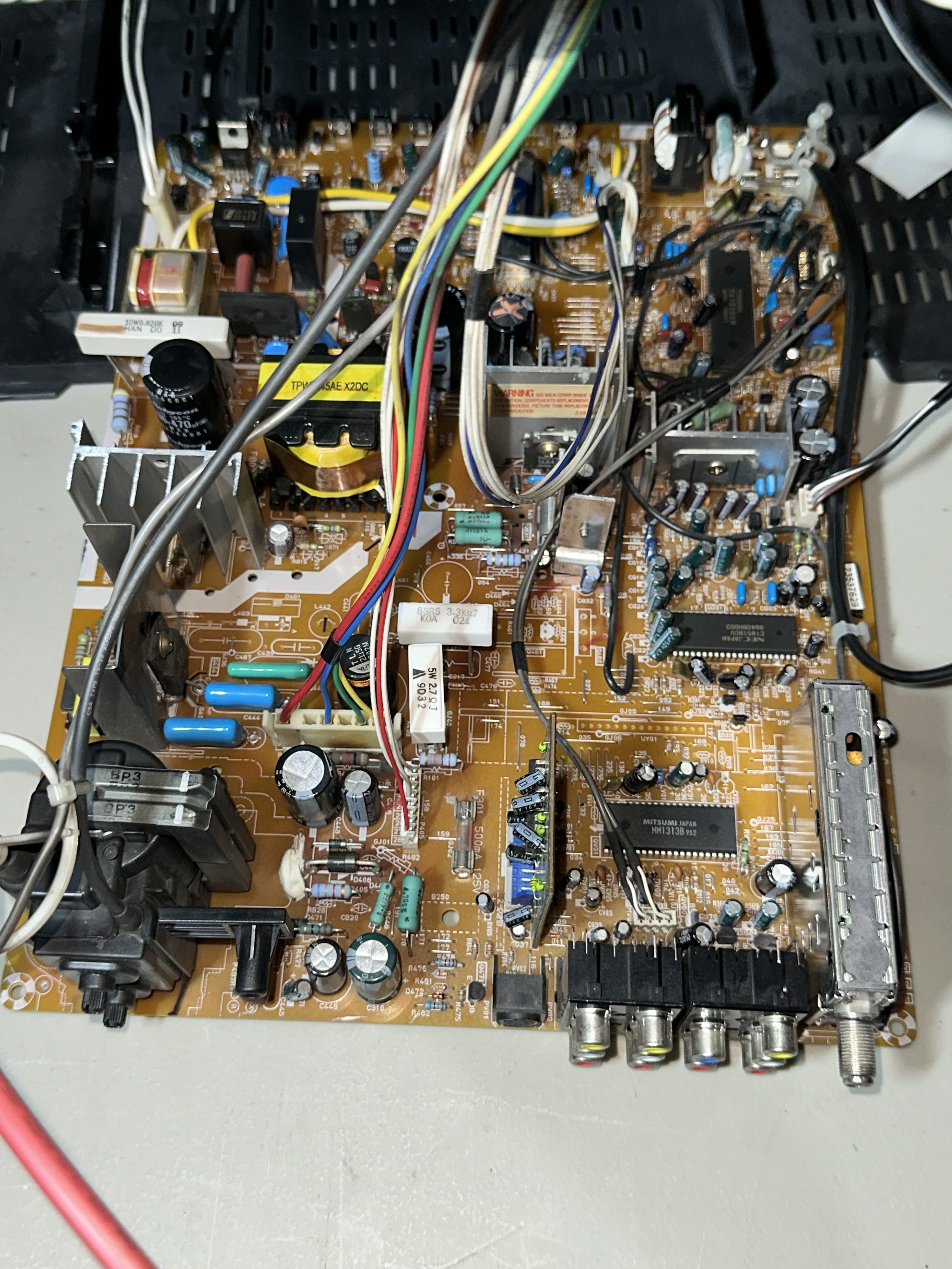
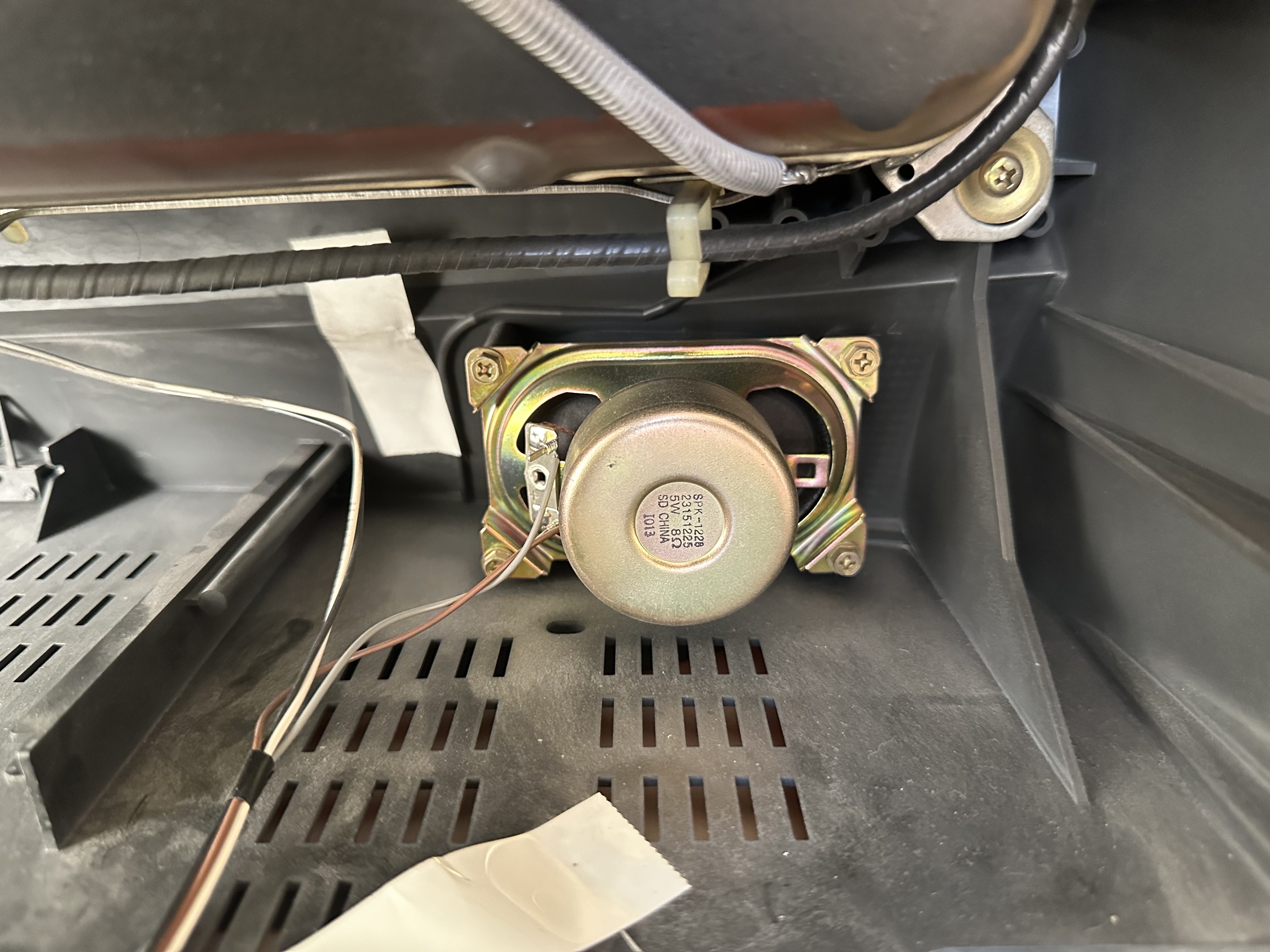
Back open 