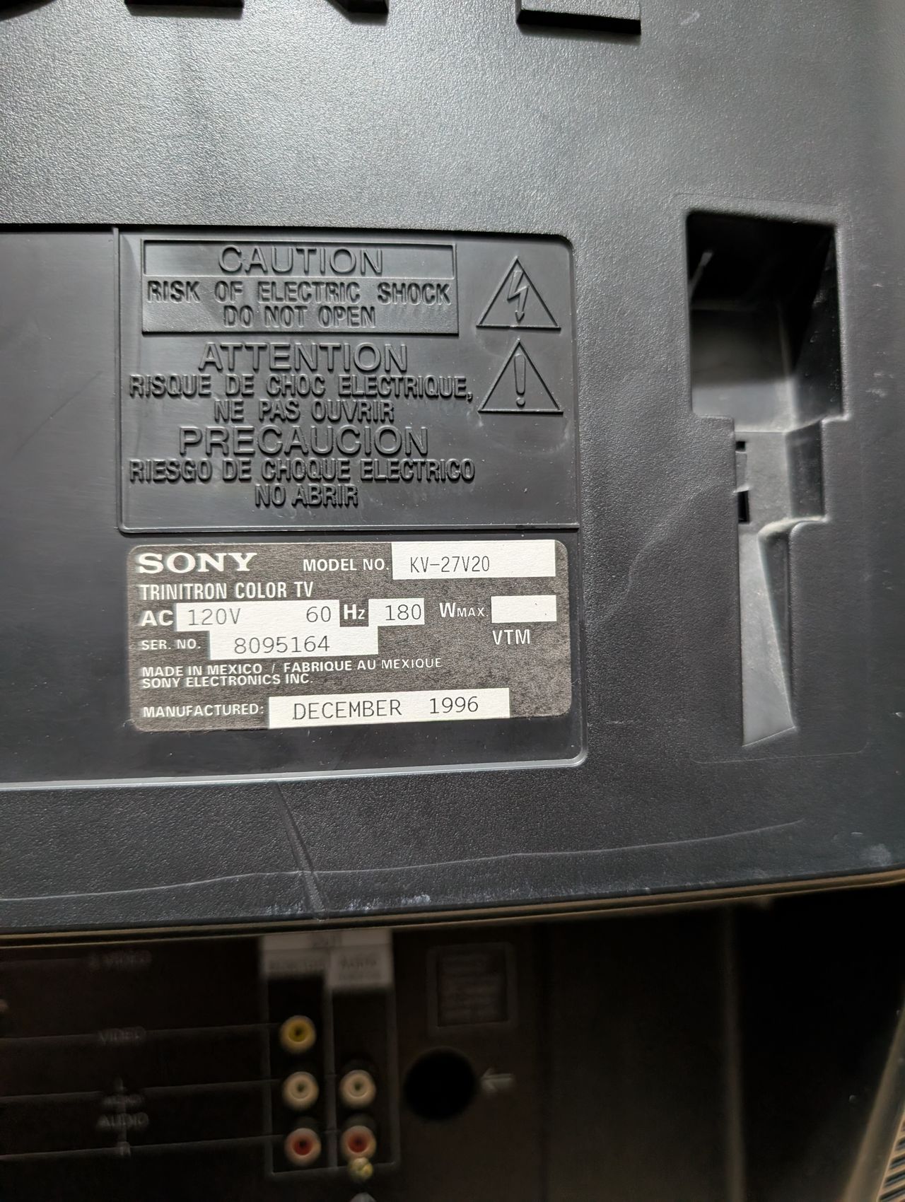
Sony (AA-2) KV-27V20
Sony (AA-2) KV-27V20 CRT RGB mod
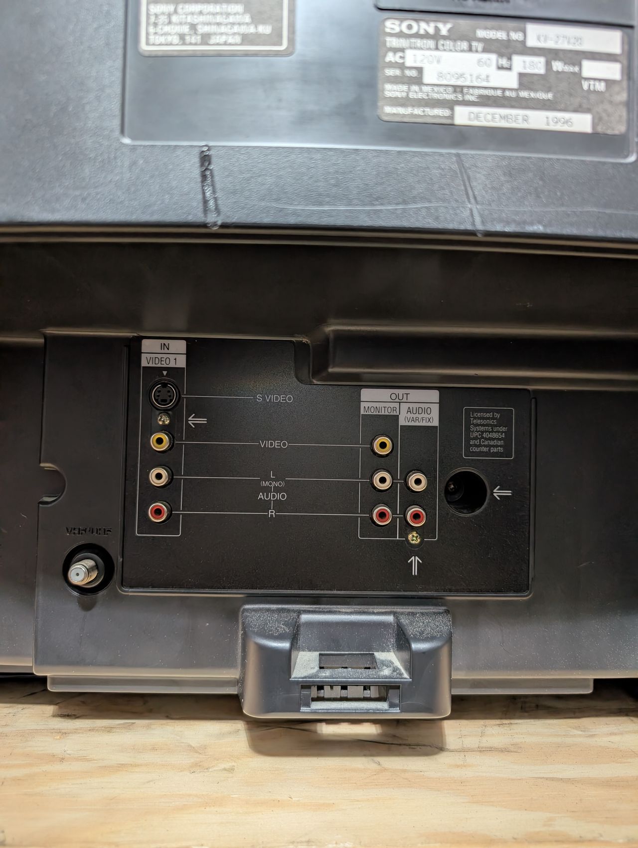
The Sony Trinitron KV-27V20 is a 27-inch CRT TV featuring a Hi Black Trinitron picture tube, built-in 5W stereo speakers with SRS sound, and an automatic light sensor for brightness adjustment. It offers front and rear composite A/V inputs, a rear S-Video input, and both composite and stereo audio outputs. Video inputs accept 1V peak-to-peak signals, and audio inputs have 4.7 kΩ impedance with 500 mV sensitivity. Antenna connections include 75-ohm UHF/VHF terminals. Power consumption is 160 W (on) and 9 W (standby). The set measures about 27" × 23" × 20" and weighs 94 lbs.
Sound on this set really stands out. This set is RGB and component moddable.
View full CRT details and more mod examples →
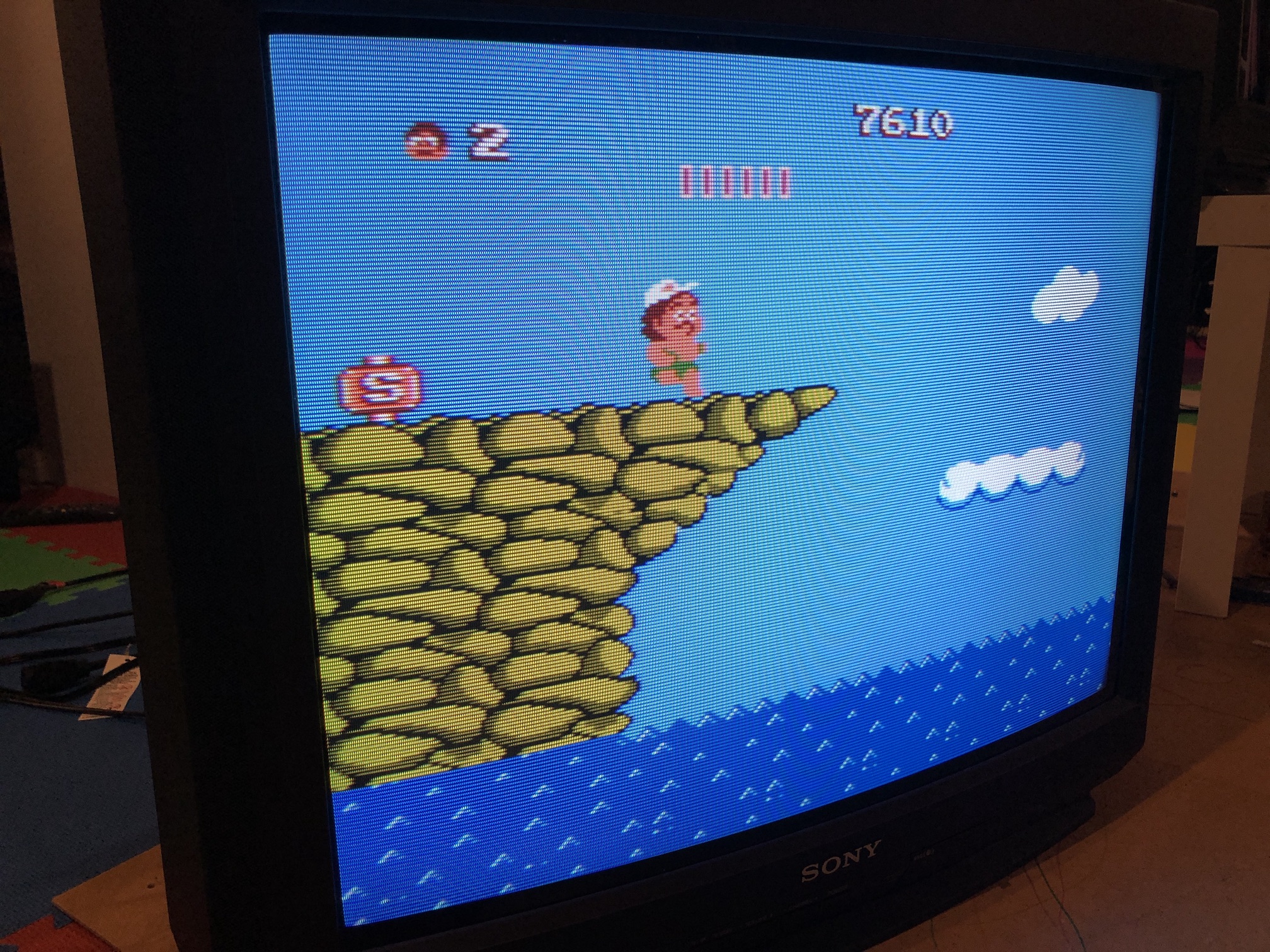
Table of Contents
Contributors
Thank you to everyone who contributed to this guide:
- Sunthar — showcase author
- Michael Lopez — showcase author
CRT safety
Caution
You can die doing this! So read carefully! CRT TV is not a toy. Do not open a CRT TV. If you don't have any prior knowledge about handling high voltage devices, this guide is not for you. CRT TV contains high enough voltage (20,000+ V) and current to be deadly, even when it is turned off.
Plan of attack
Manuals and Datasheets
- Sony KV-27V20 Service Manual
- Sony KV-27V20 Service Manual
- Sony KV-27V20 Service Manual
- Sony CXA2025AS Datasheet (Jungle)
- CXP8564D-004S Datasheet (OSD)
Specs
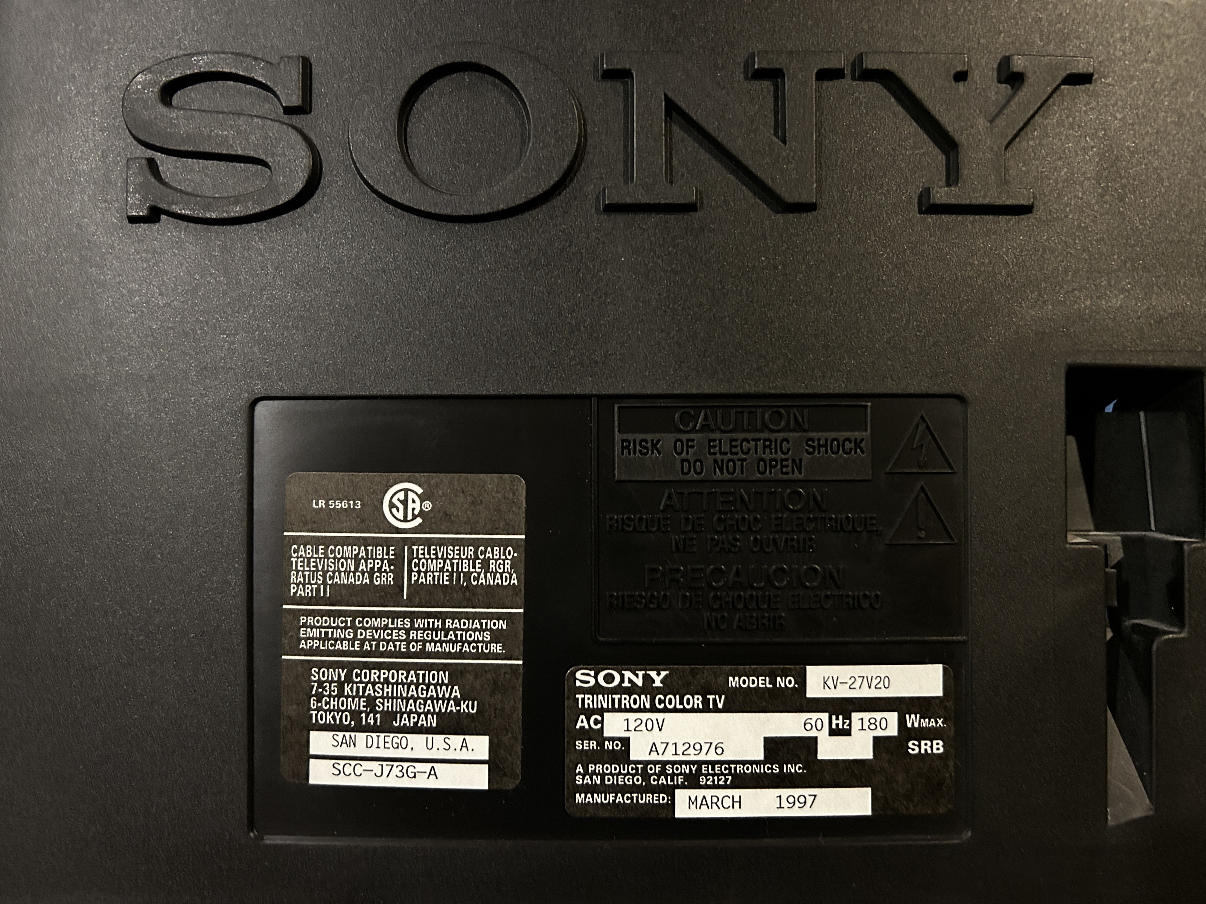
- Manufactured: USA (1997)
- Format: NTSC
- Chassis: AA-2
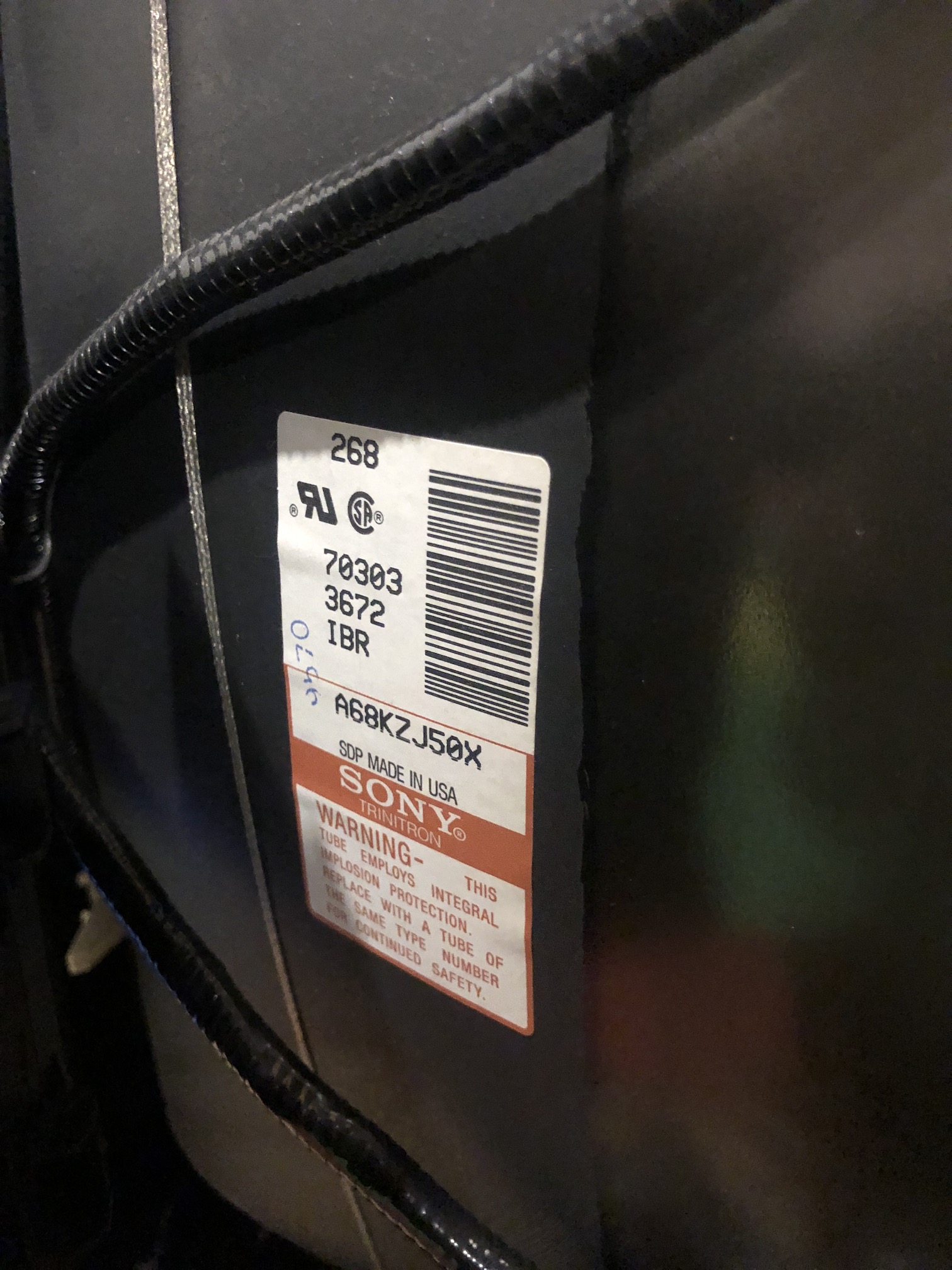
- Tube: Sony Trinitron A68KZJ50X
- Jungle Chip: Sony CXA2025AS
- OSD Chip: CXP8564D-004S
- Screen Size: 27"
- Weight: 89.5 lbs
- Inputs: Composite, RF
RGB mux diagram
Prepare the mux diagram. If you are building your own circuit, this diagram should help.
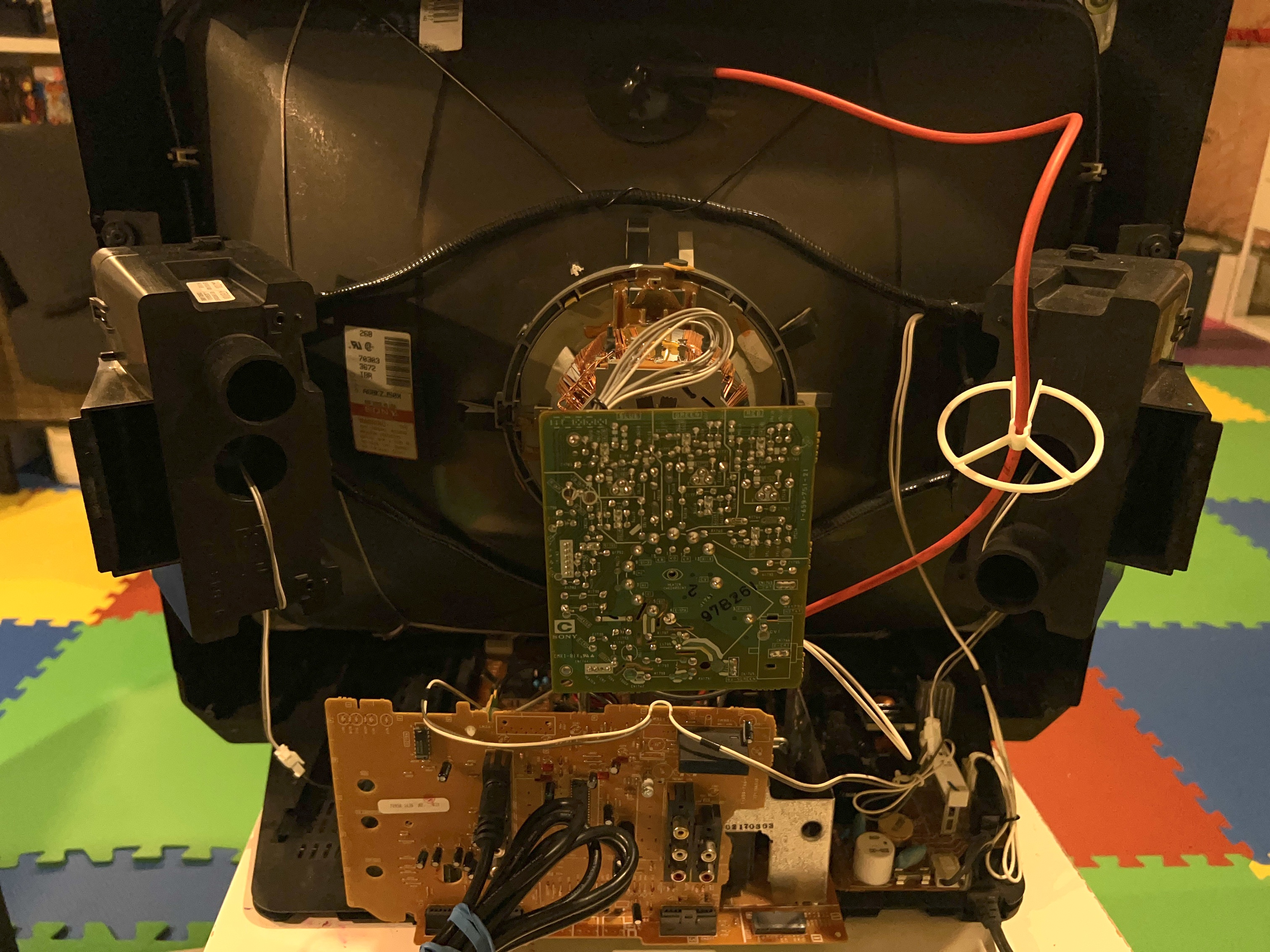
Performing the mod
STEP 1: Remove the following components
Remove R1123, R1128 and R133 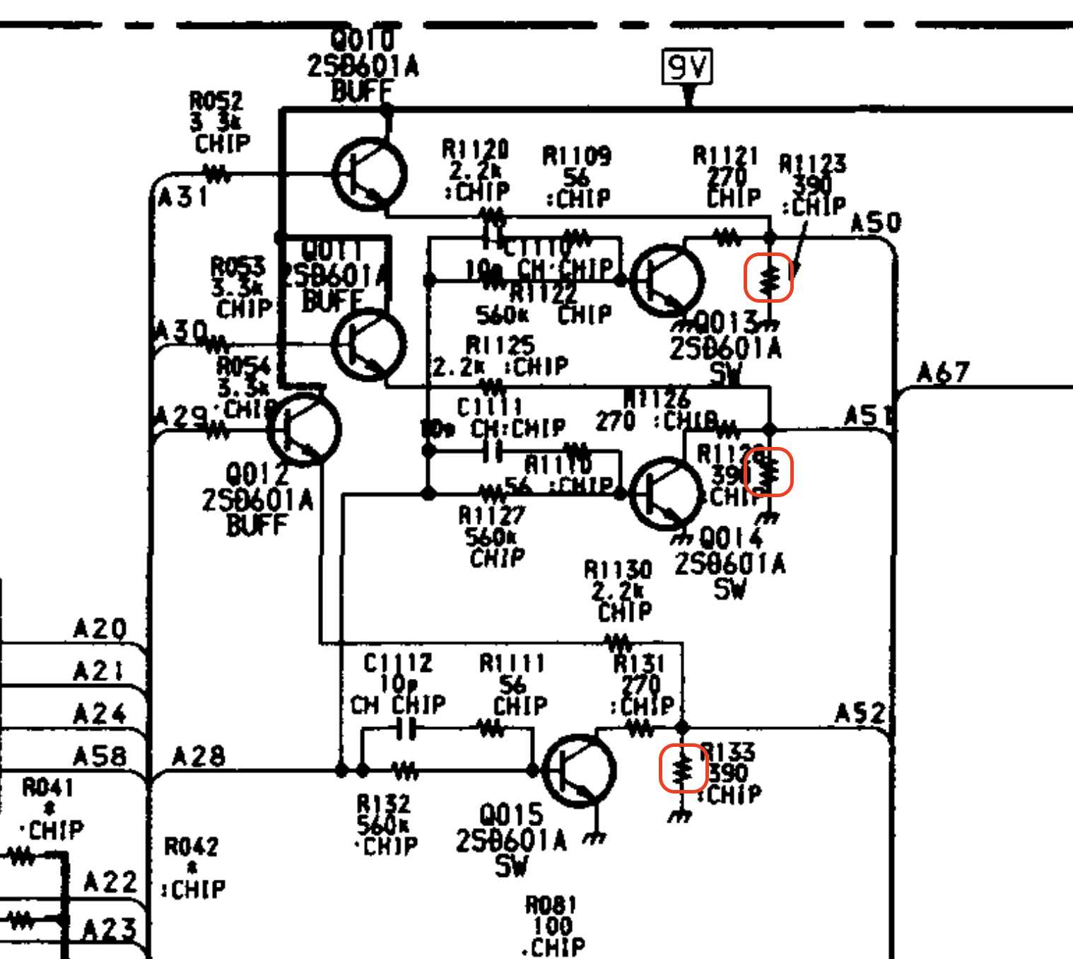
Inject R, G, B at the below locations R1123 (Red) R1128 (Green) R133 (Blue)
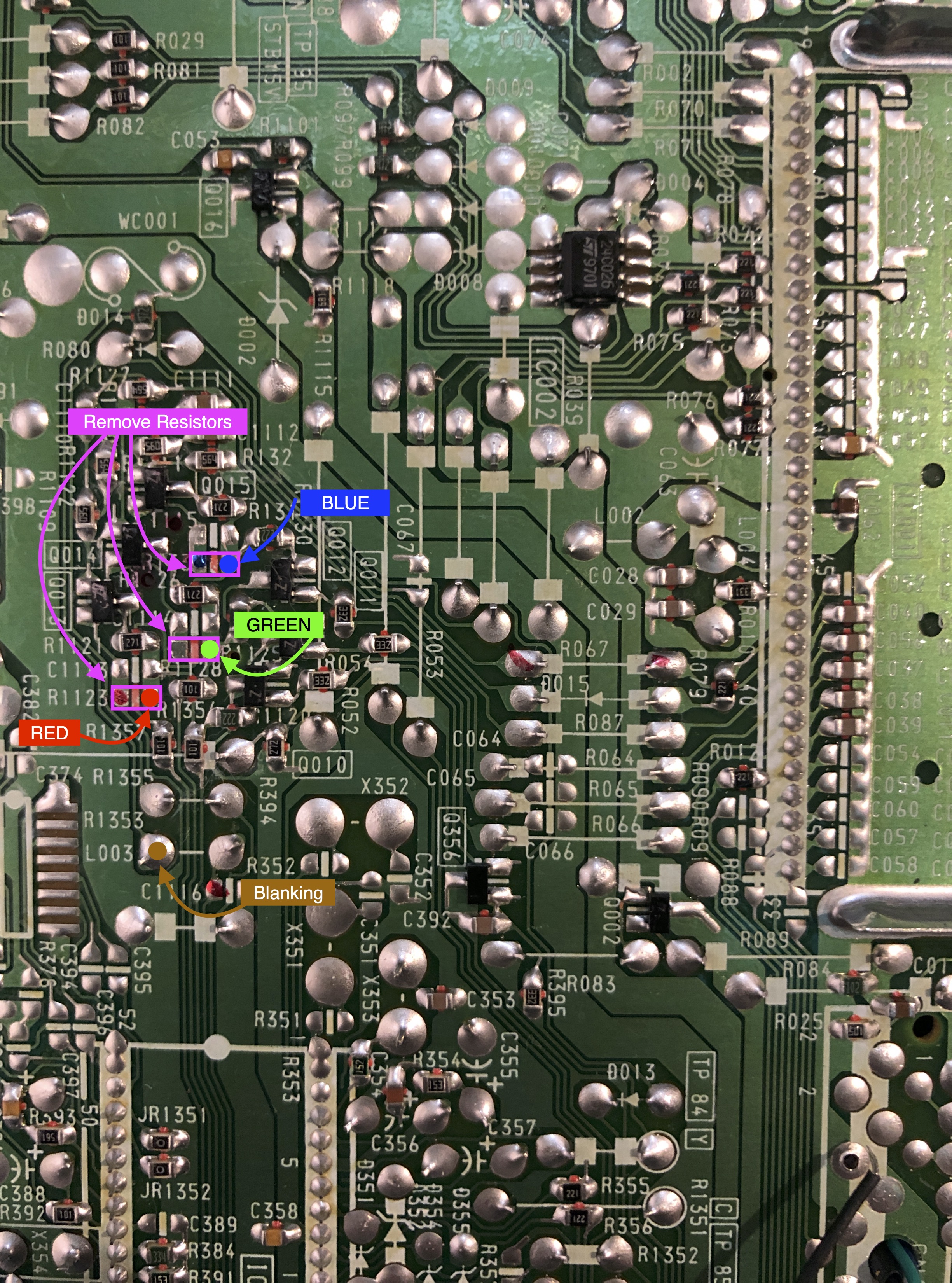
STEP 2: Add a diode to blanking
Blanking diode added. Helps reduce interference. This mod was performed without shielded cables internally and absolutely no interference was noticed.
![]()
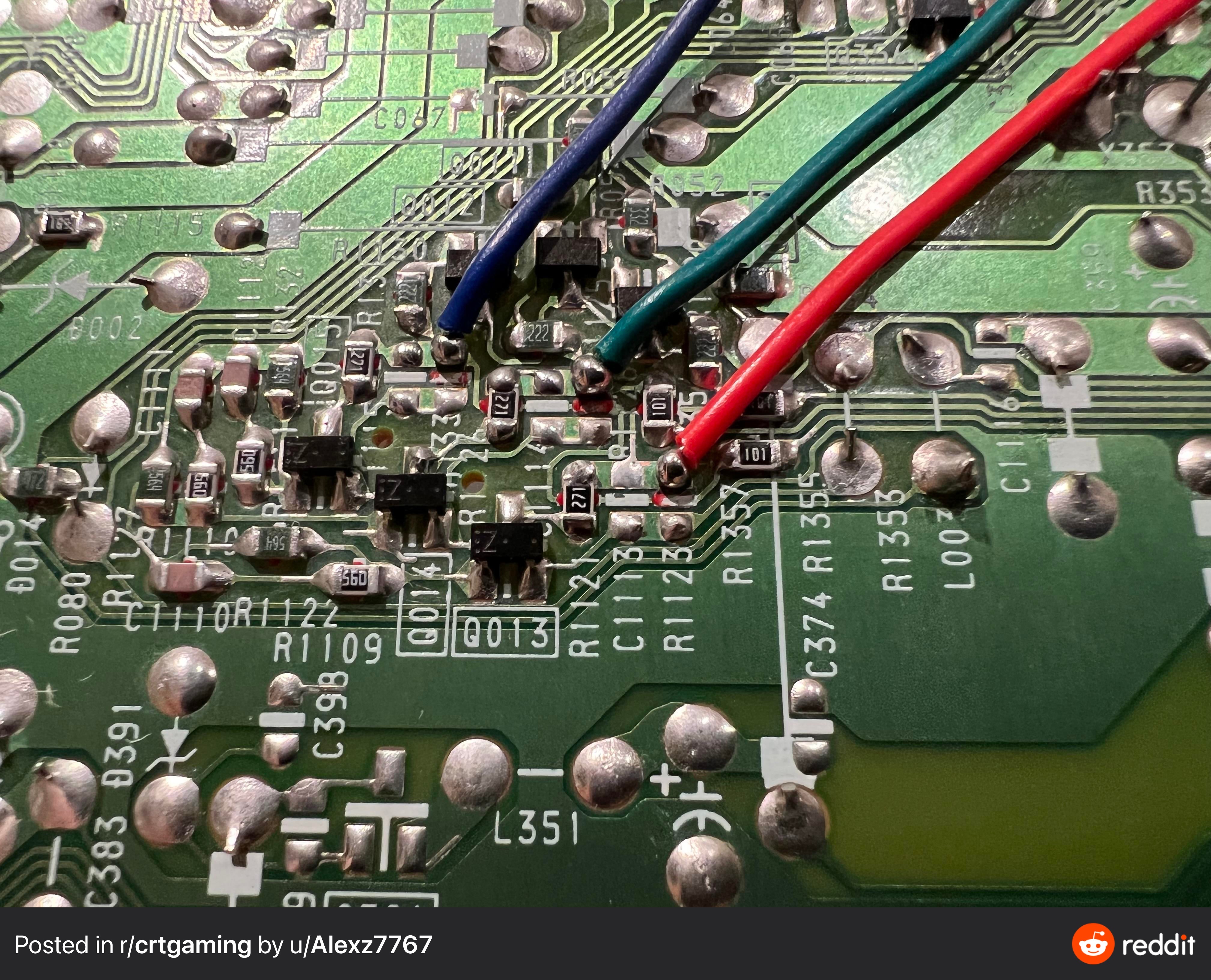
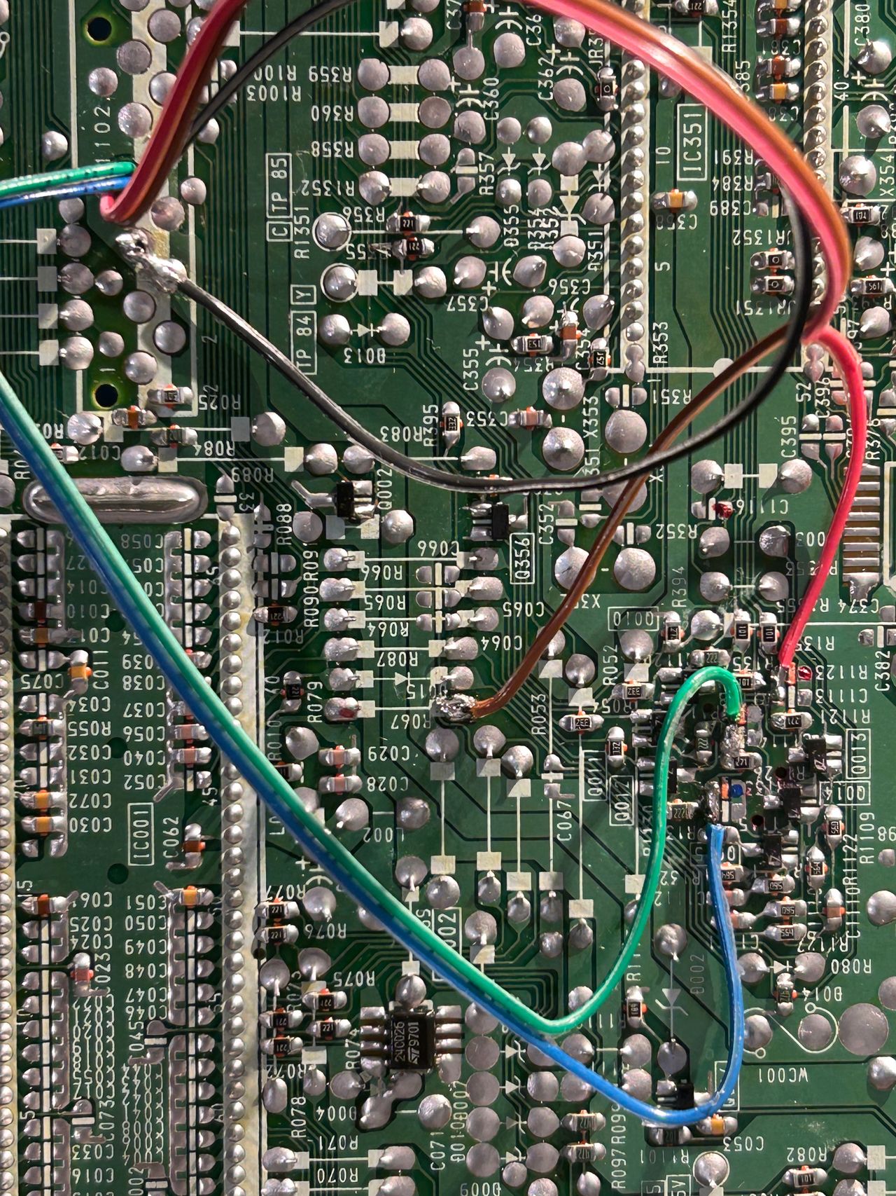
STEP 3: Connect RGB and blanking wires
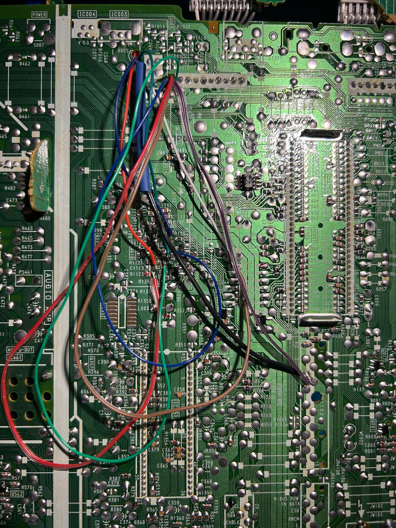
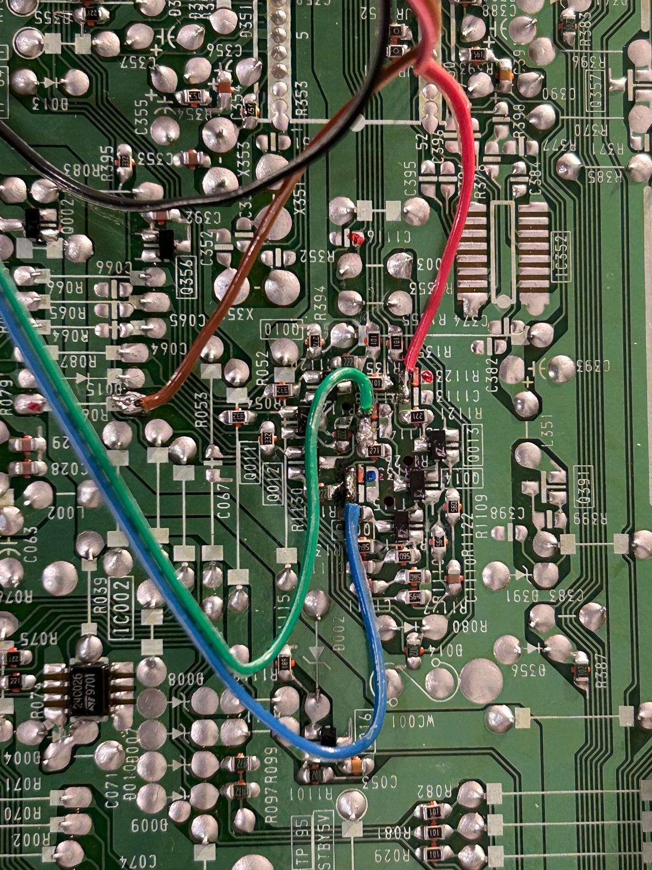
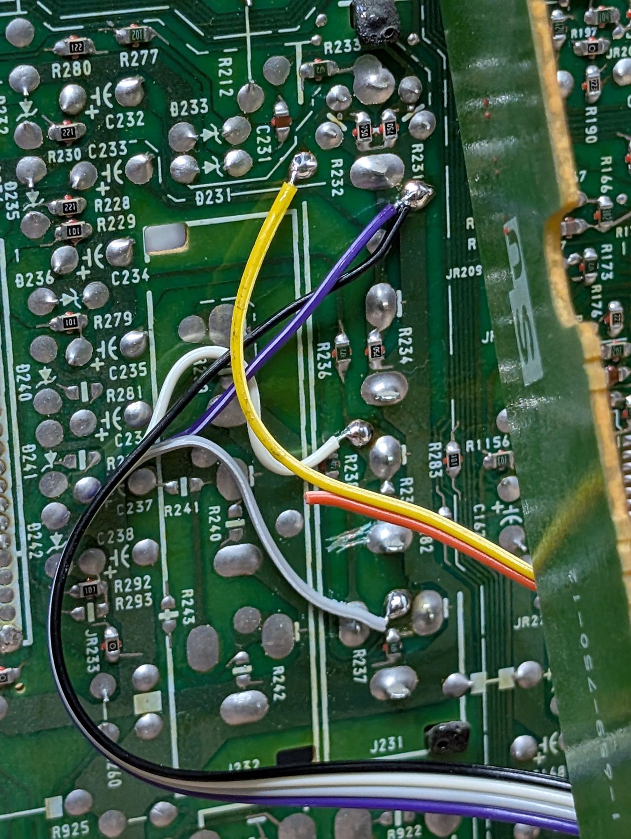
Refer to the image below for the precise soldering points for the red, green, blue, and blanking wires. For the R, G, and B wires, make sure not to solder to the pad connected to the ground.
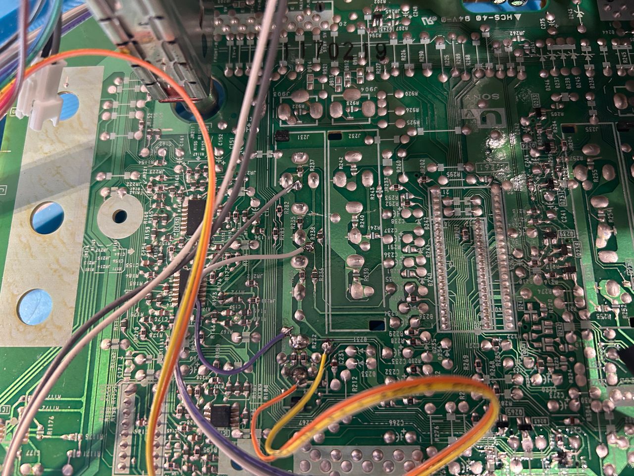
STEP 4: Connect audio, ground and sync wires
Now, it's time to turn our attention to the U board. In the image below, you can see where the audio, ground, and sync wires are connected. Since I'm using a separate cable for audio, the wire colors may not match the colors of the ribbon cable. Additionally, make sure to cut the trace as shown in the image.
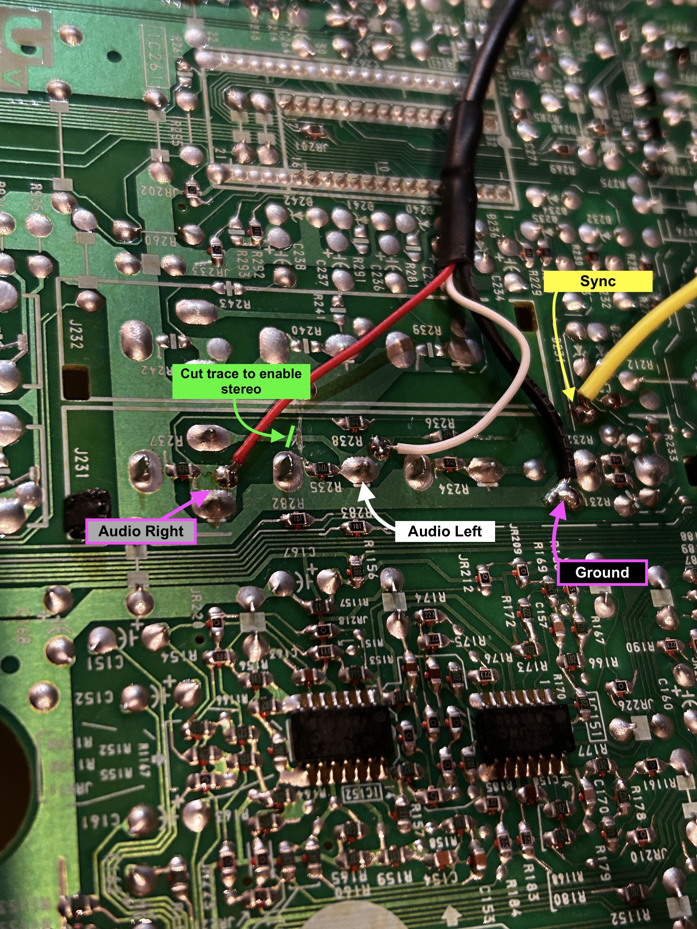
- Red wire is audio right = grey wire on ribbon cable
- White wire is audio left = white wire on ribbon cable
- Black = black (common ground)
- Yellow = yellow (sync using luma input)
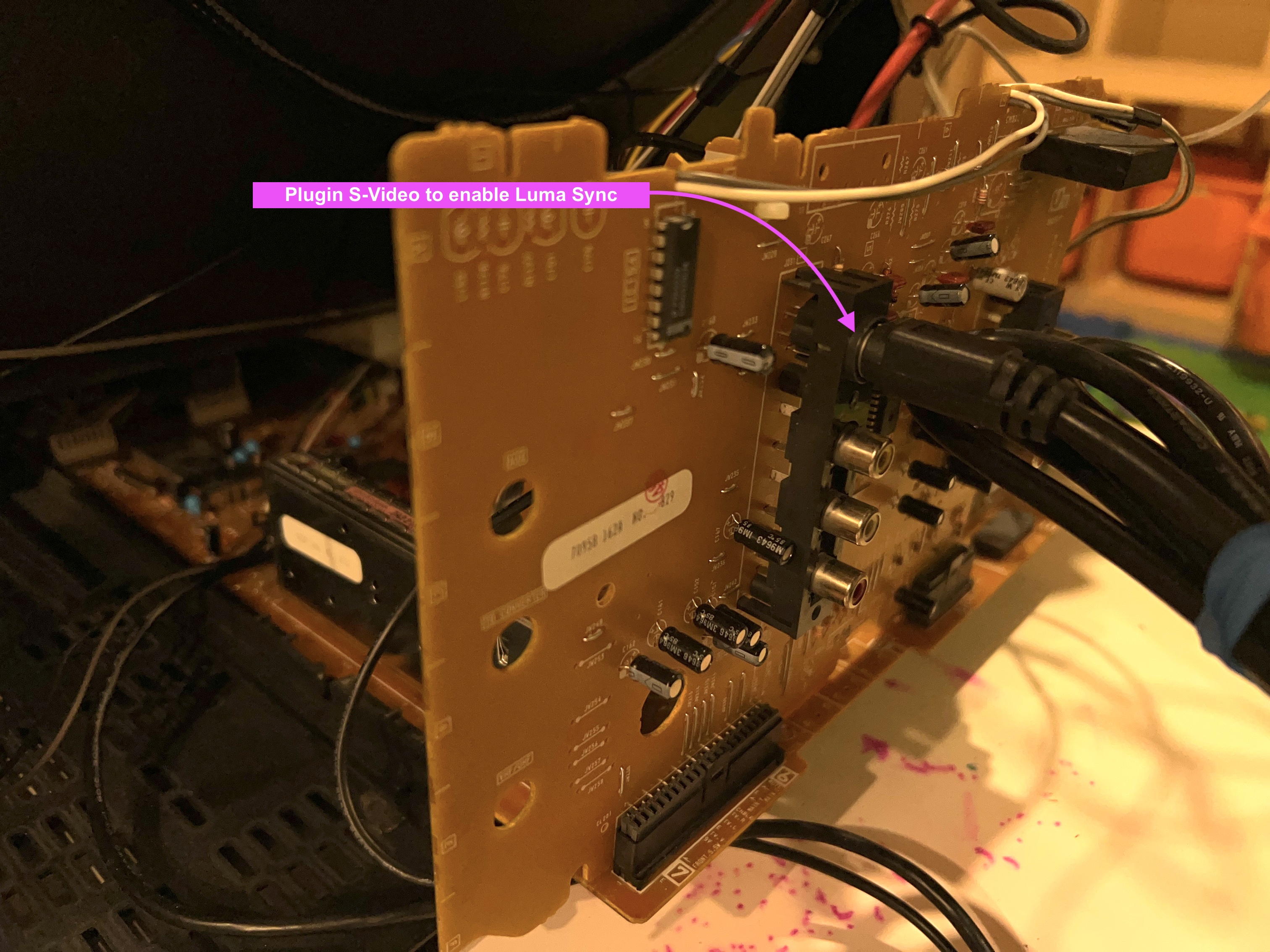
To enable the luma input, I chose to use a dummy S-Video plug. Essentially, this means simply plugging an S-Video cable into the S-Video port without connecting it to anything else. You can get creative with this setup—adding a switch to toggle luma on and off, permanently enabling luma, or even using a transistor to activate luma automatically when a SCART cable is connected using the 5V blanking signal. However, I opted for a straightforward and reliable solution with the dummy plug. This approach allows me to seamlessly use both S-Video and Composite input from the back panel whenever needed.
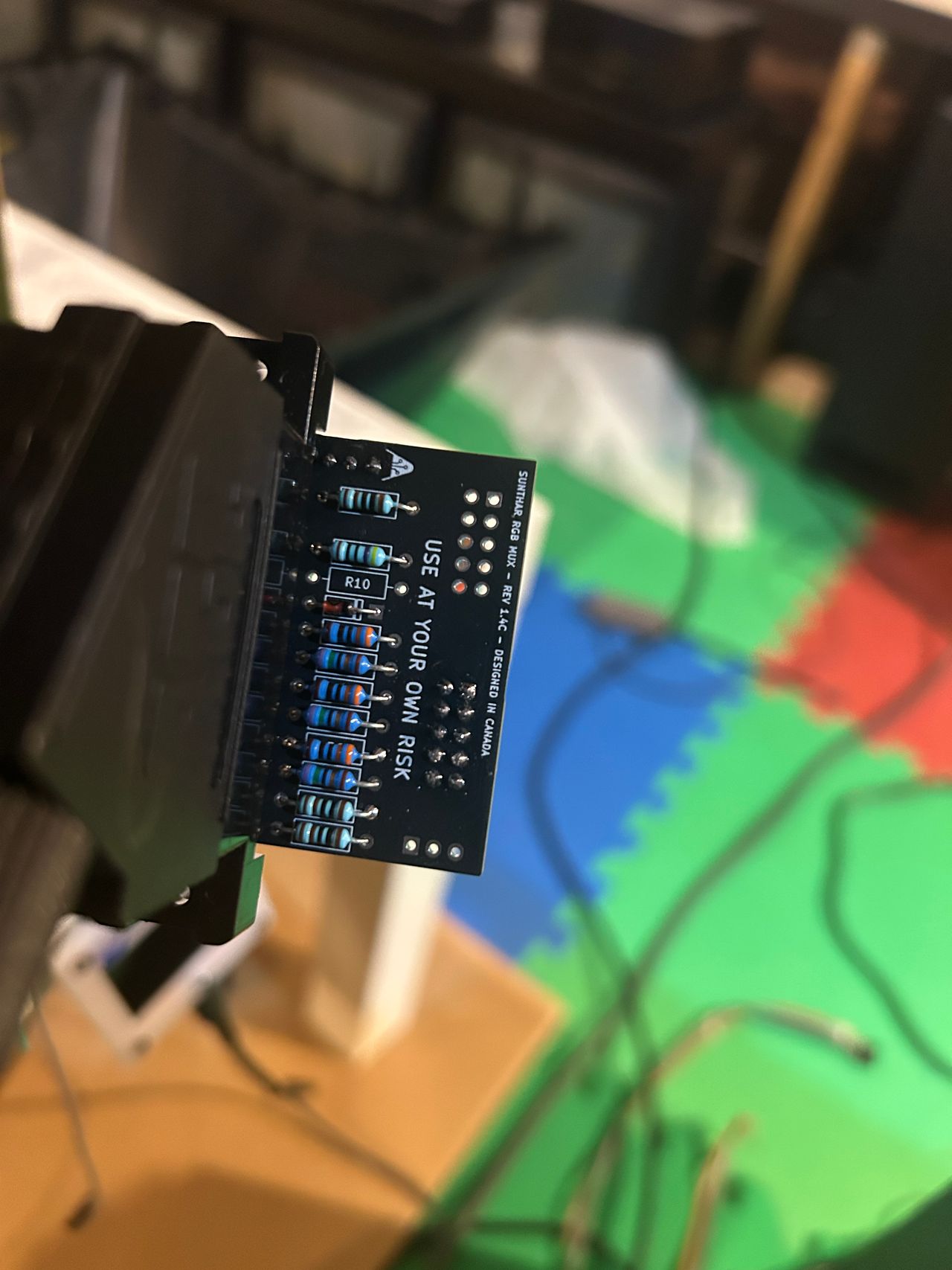
STEP 5: Build your mux circuit
This mod uses the RGB mux board. This is optional, but will make your mod easier and stable. You can also create the circuit presented in the schematics above without the board. Please also checkout the mux calculator to play with your own values.
| On Sony CRT Chassis | KV-27V20 |
|---|---|
| CRT RGB inline resistor | 2.2kΩ |
| CRT RGB ground resistors removed | 390Ω |
| 0.1μF caps replaced | No |
| Add diodes on chassis RGB lines? | No |
| Add blanking diode on chassis | Yes |
| RGB mux board | KV-27V20 |
|---|---|
| Mux board RGB termination (R1, R2, R3) | 75Ω |
| Mux board RGB inline resistors (R4, R5, R6) | 330Ω |
| Mux board Audio LR (R7, R8) | 1kΩ |
| Mux board blanking diode (R9) | 1N4148 |
| Mux board blanking ground resistor (R10) | open |
| Mux board blanking resistor (R11) | 470Ω |
| Mux board transistor base resistor (R12) | 1kΩ |
| Mux board transistor (Q1) | PN2222A |
Compatible mux boards:
It is important to note that the blanking ground resistor (R10) is necessary to prevent strange black backgrounds from appearing on the KV-27S22 OSD text.
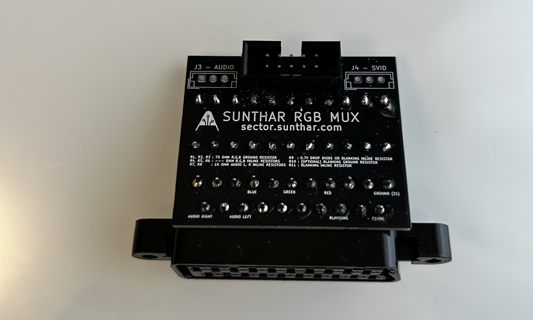
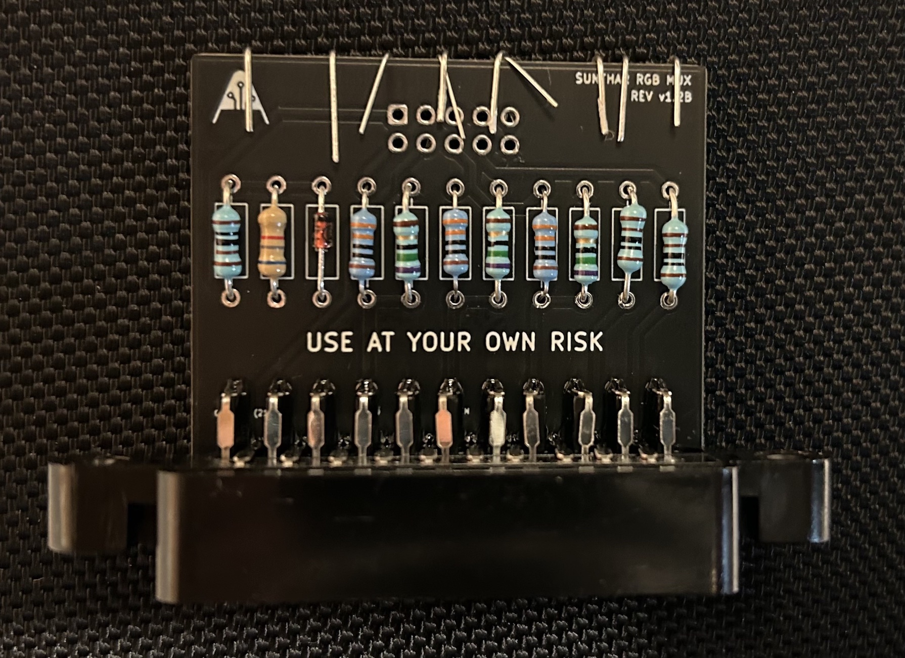
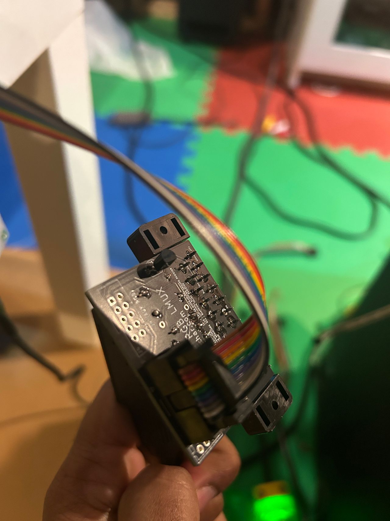
Picture of RGB mux rev B board 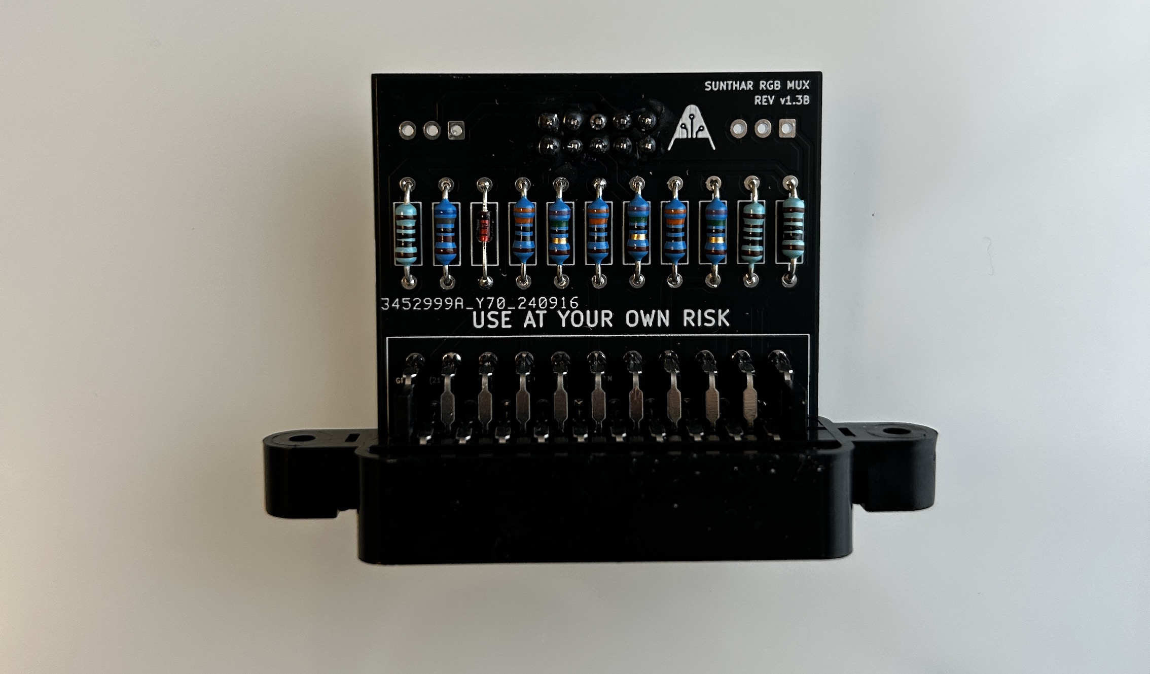
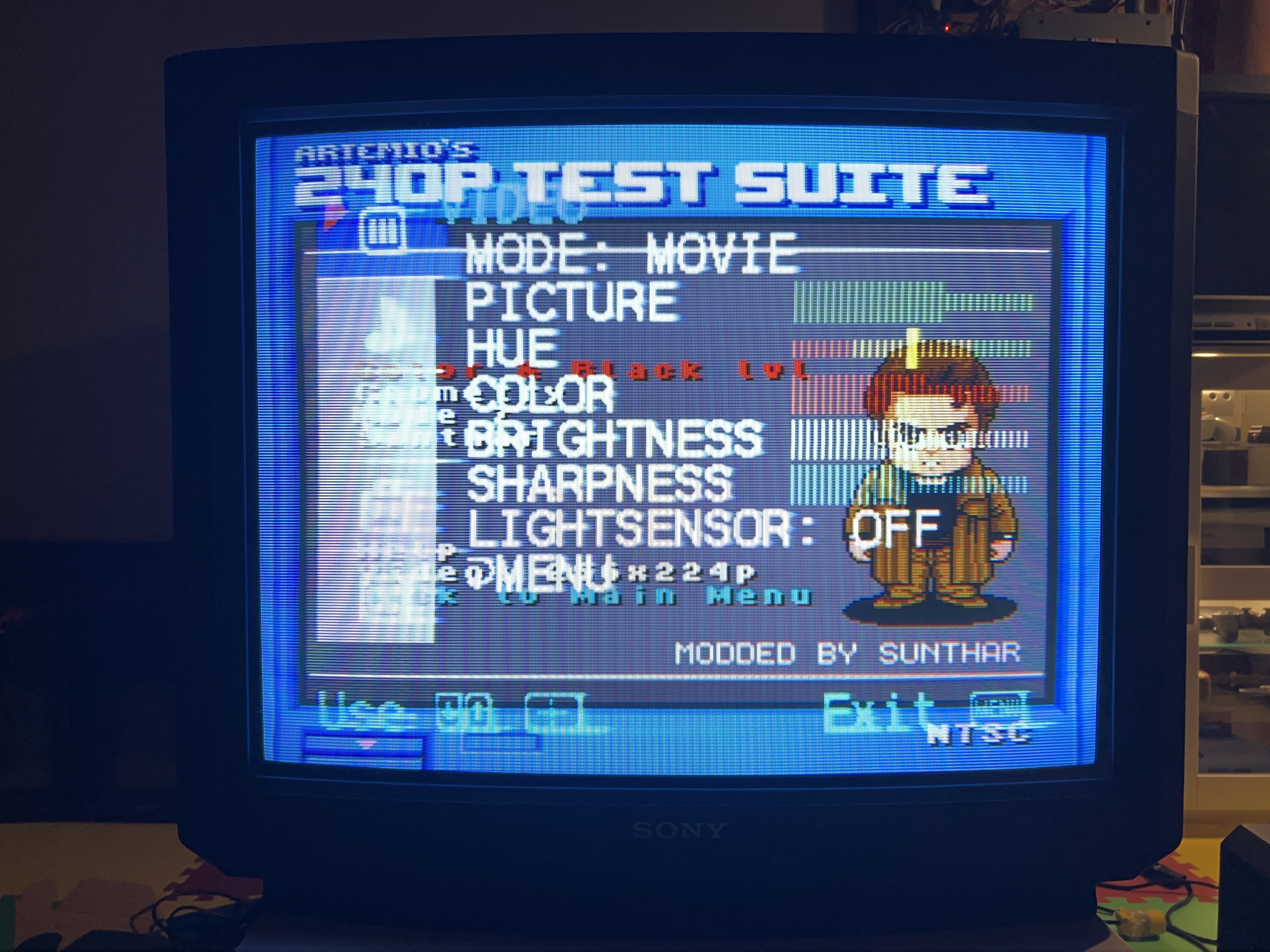
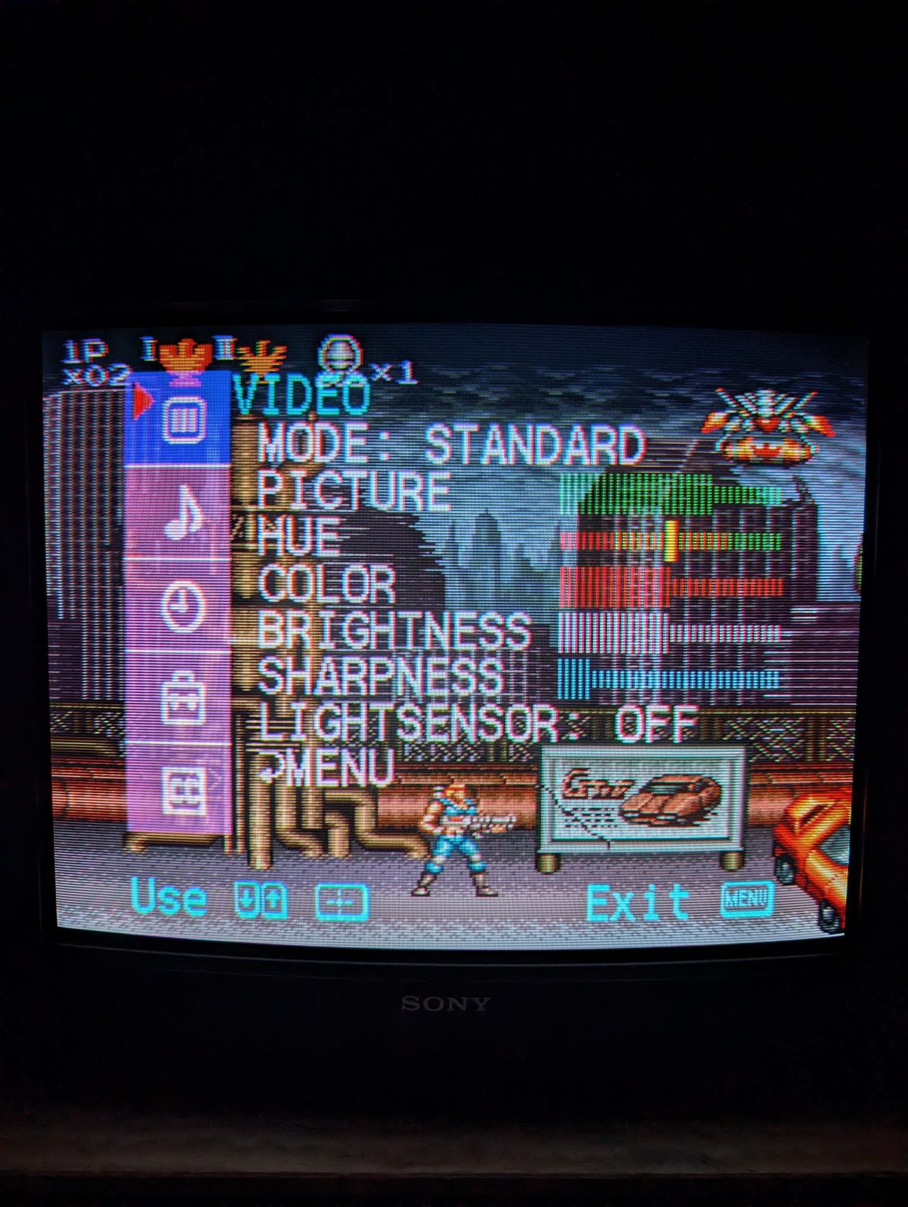
OSD mux overlay
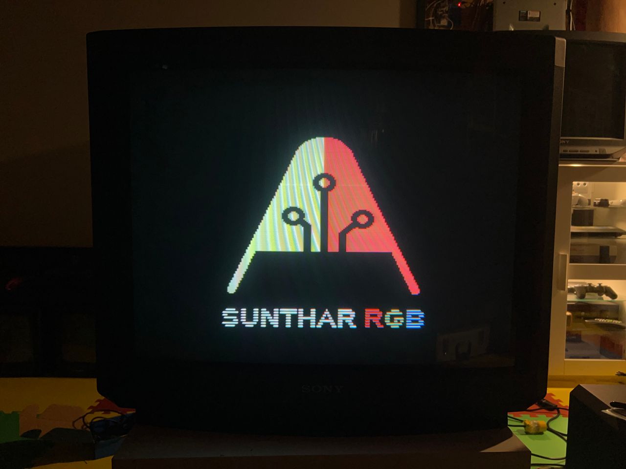
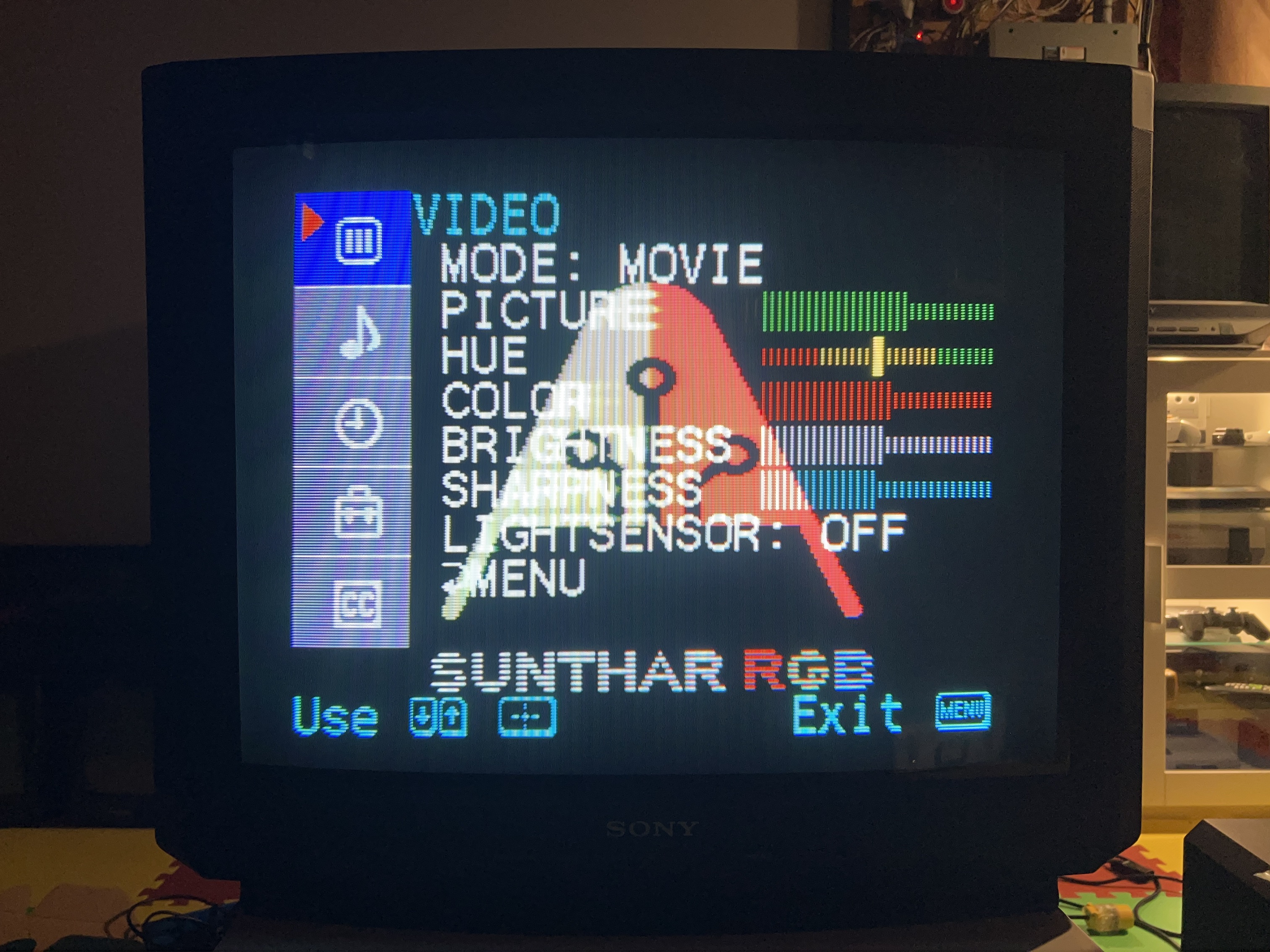
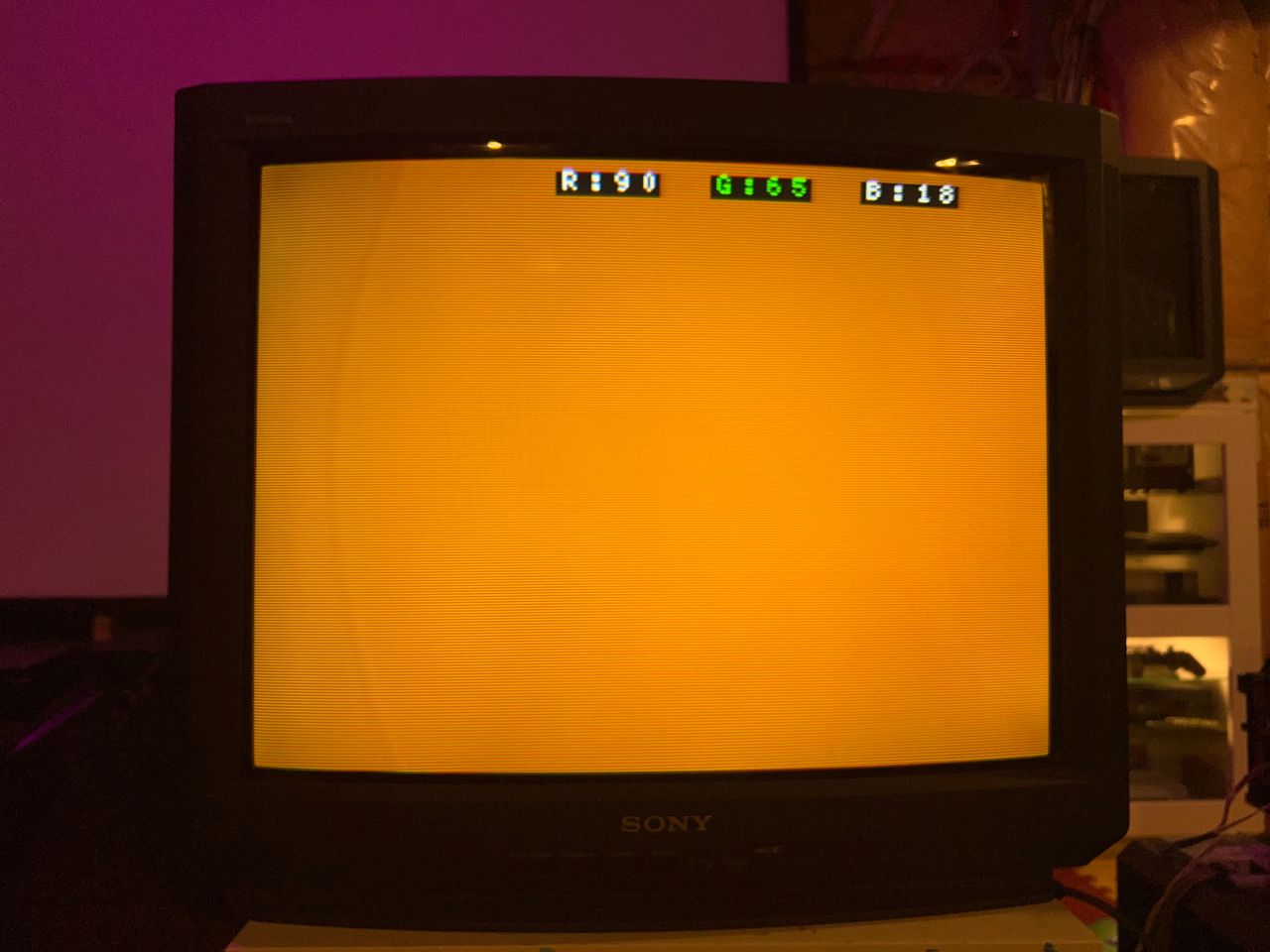
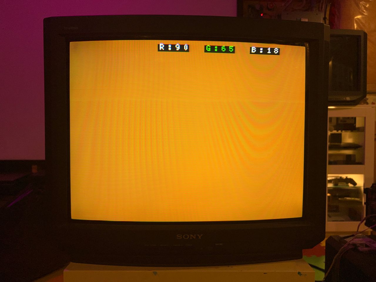
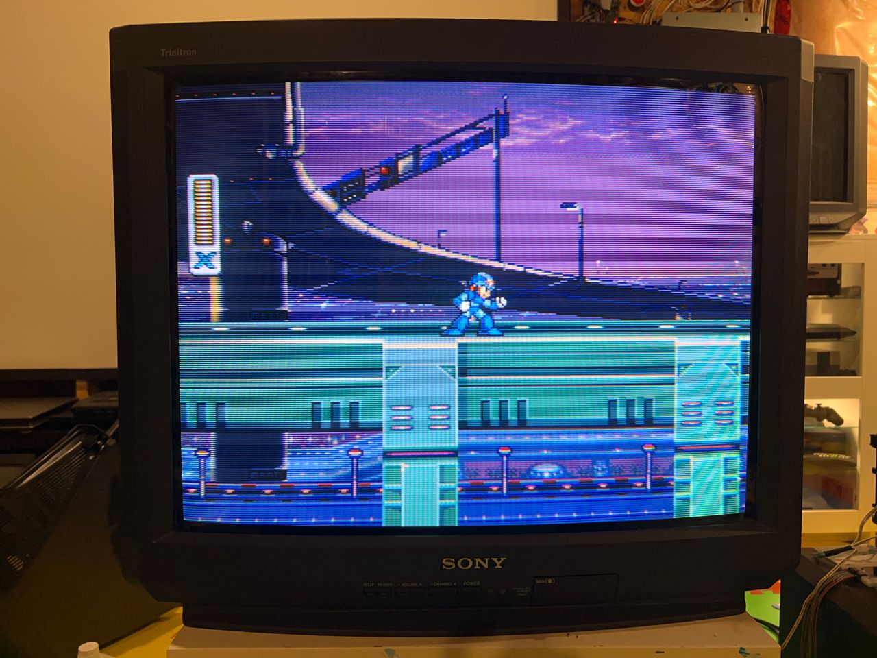
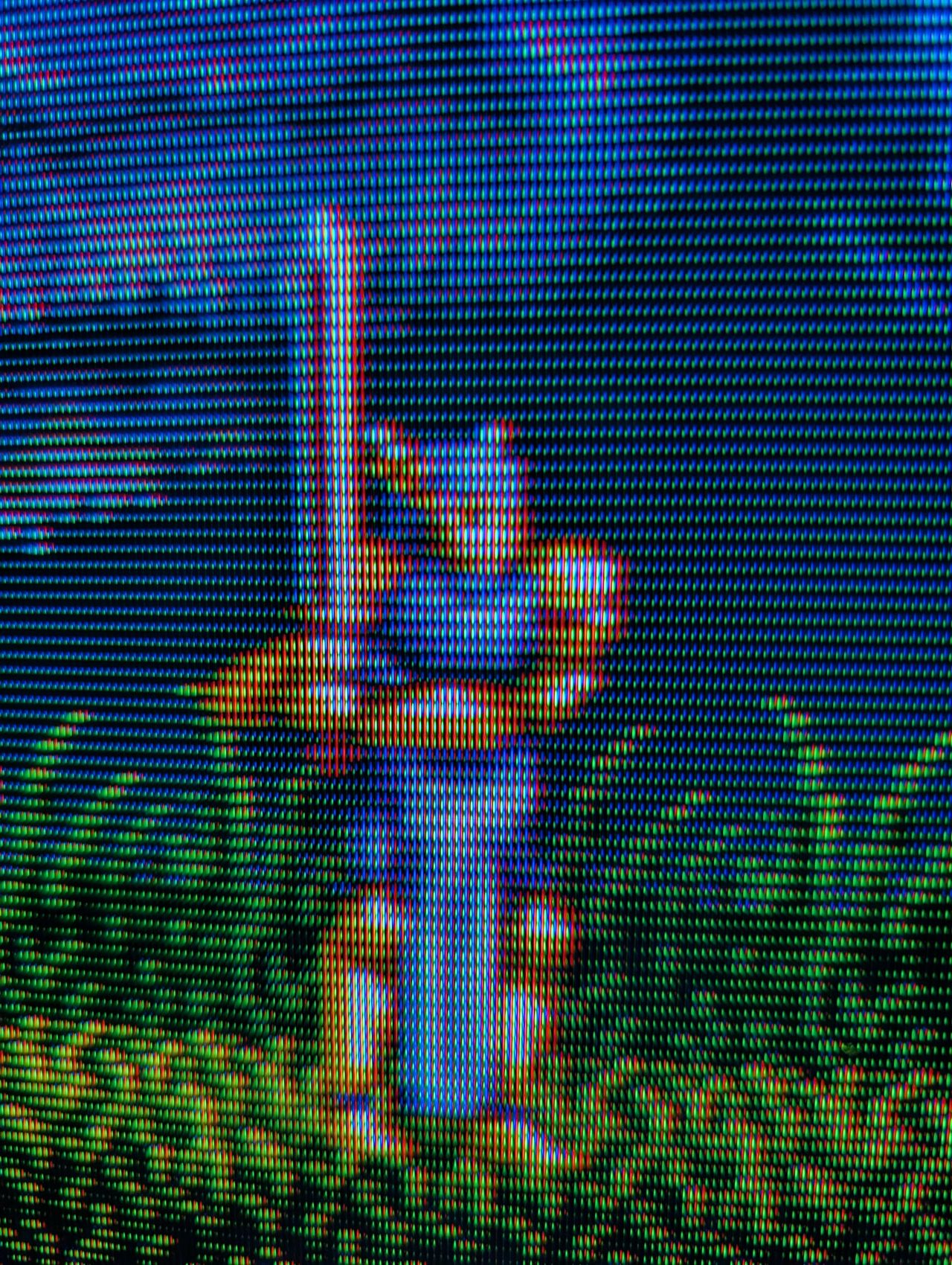
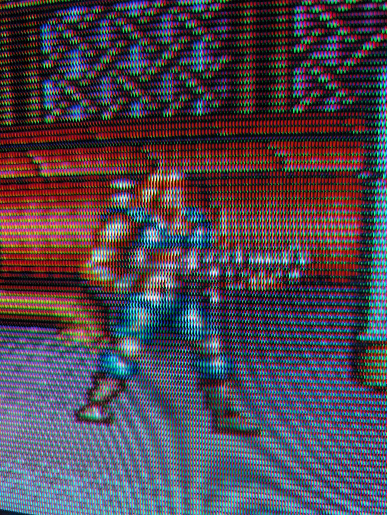
One thing to note about the OSD overlay on top of the RGB image is that it appears sharp on darker screens, but on lighter screens, some streaking is noticeable. This issue only affects the OSD. By adjusting the inline resistors, I managed to reduce the streaking slightly, but I suspect the best solution might involve using diodes in the OSD path. However, this would add complexity to the mod without providing significant benefits. It's also possible that this issue is specific to this particular set.
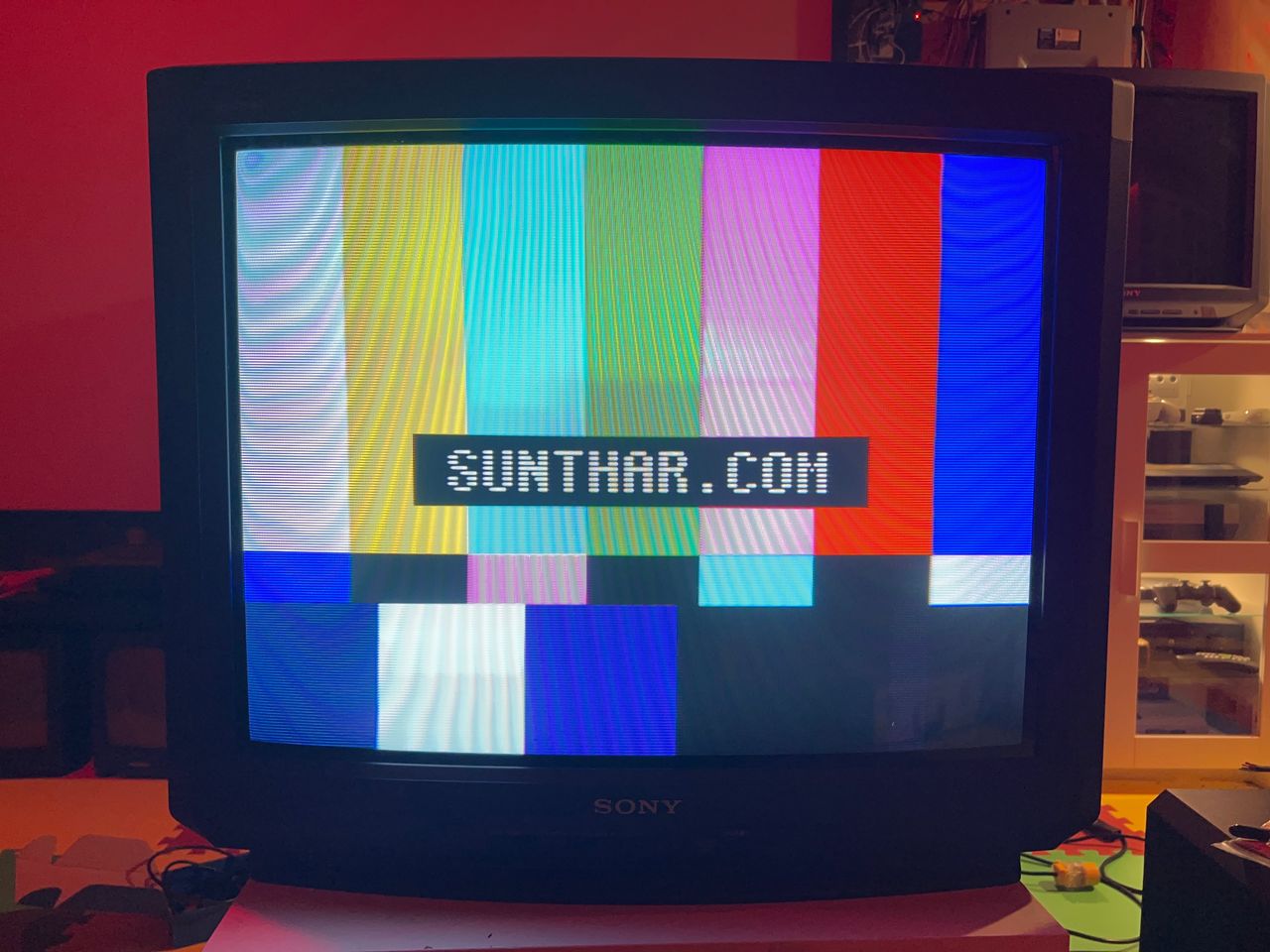
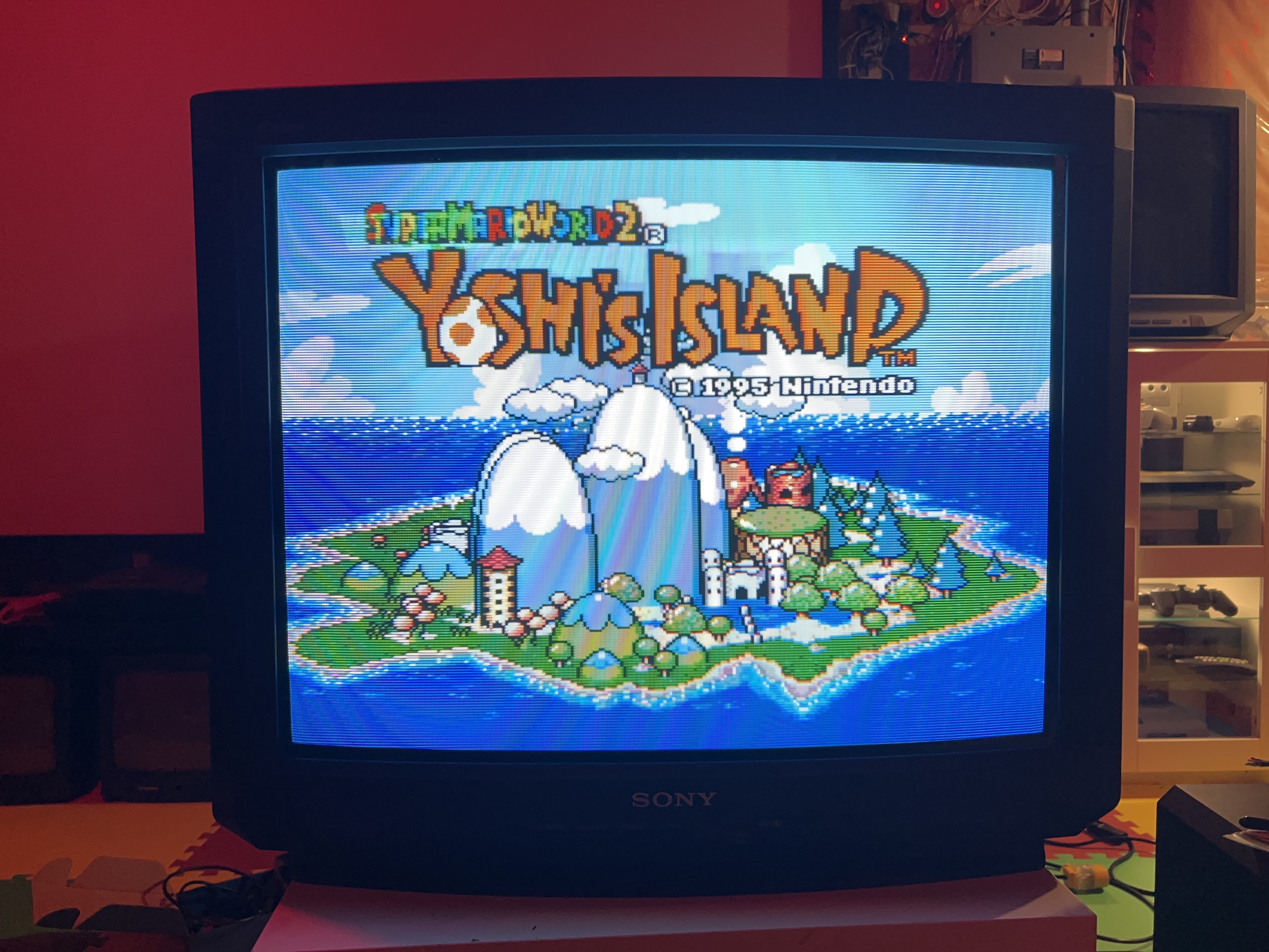
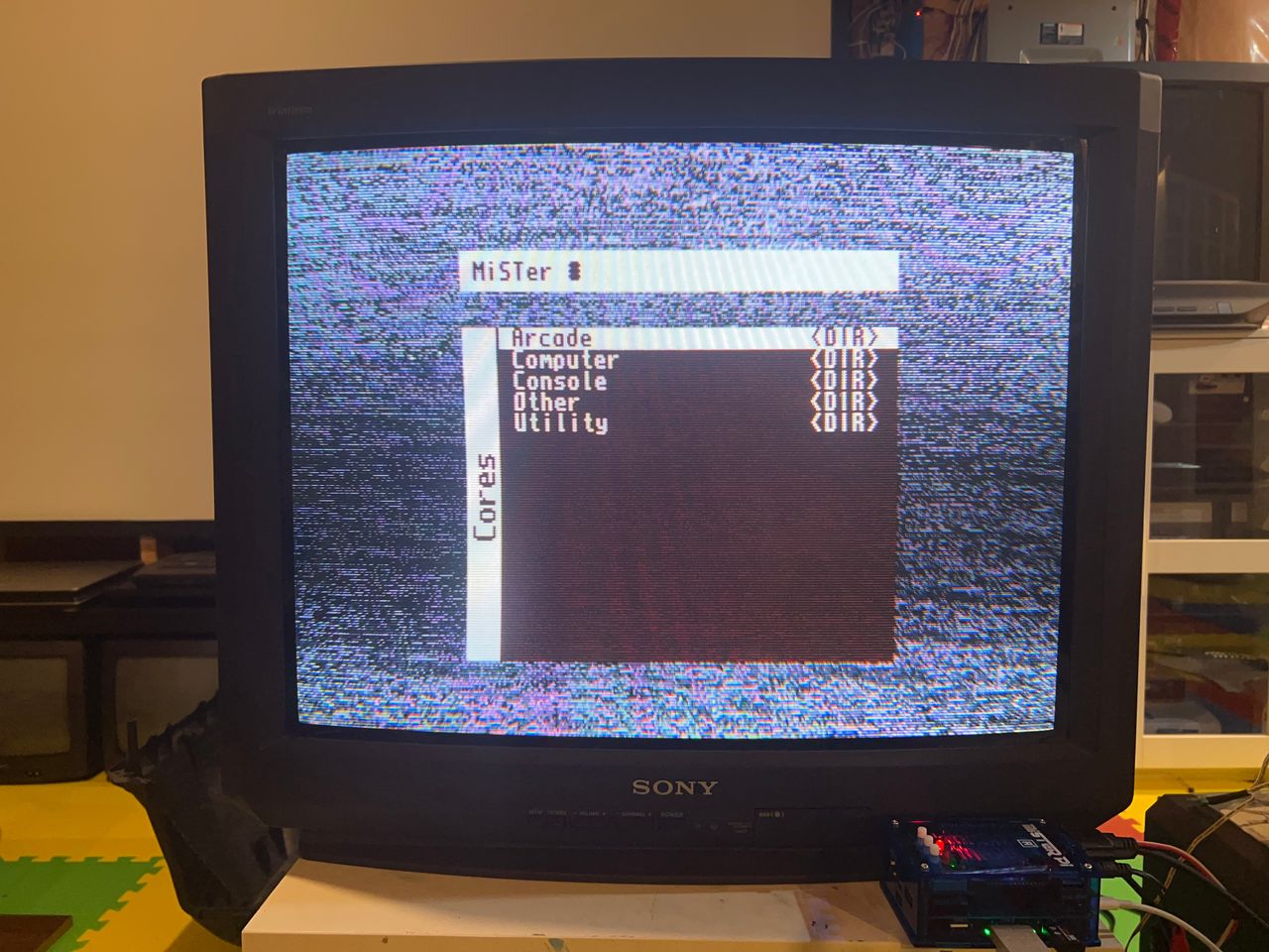
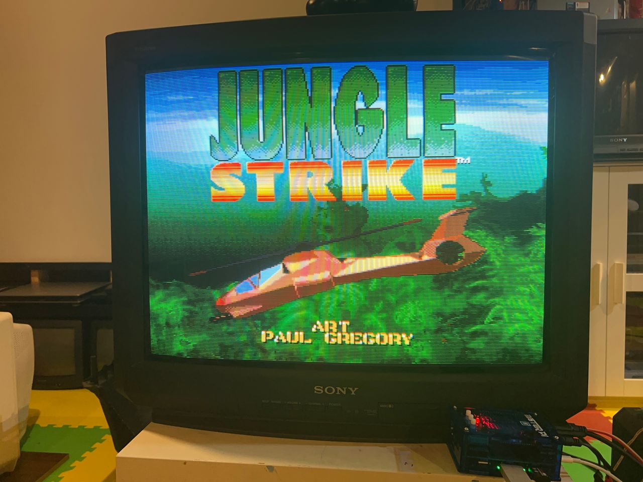
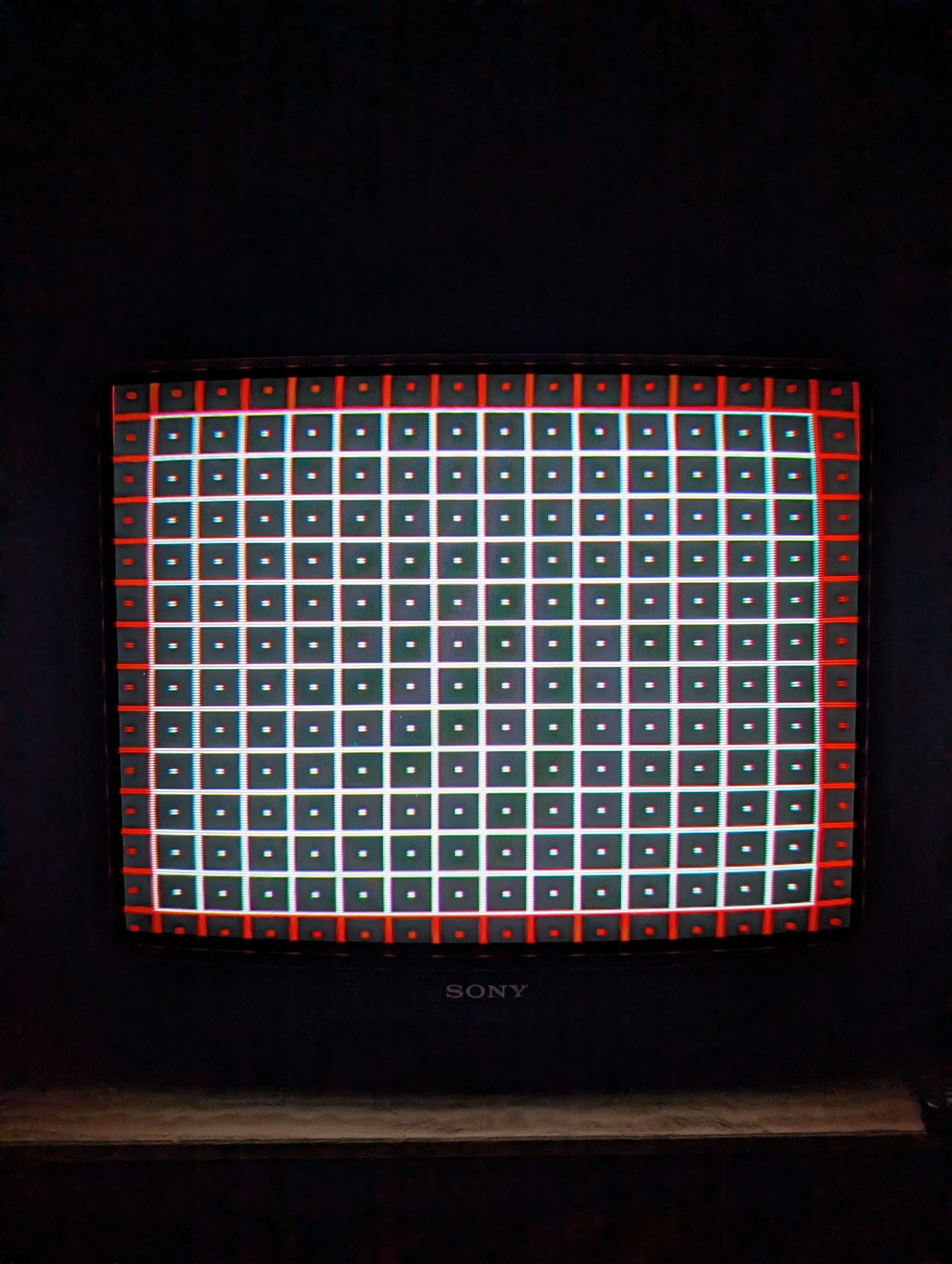
Games & Pattern

![]()
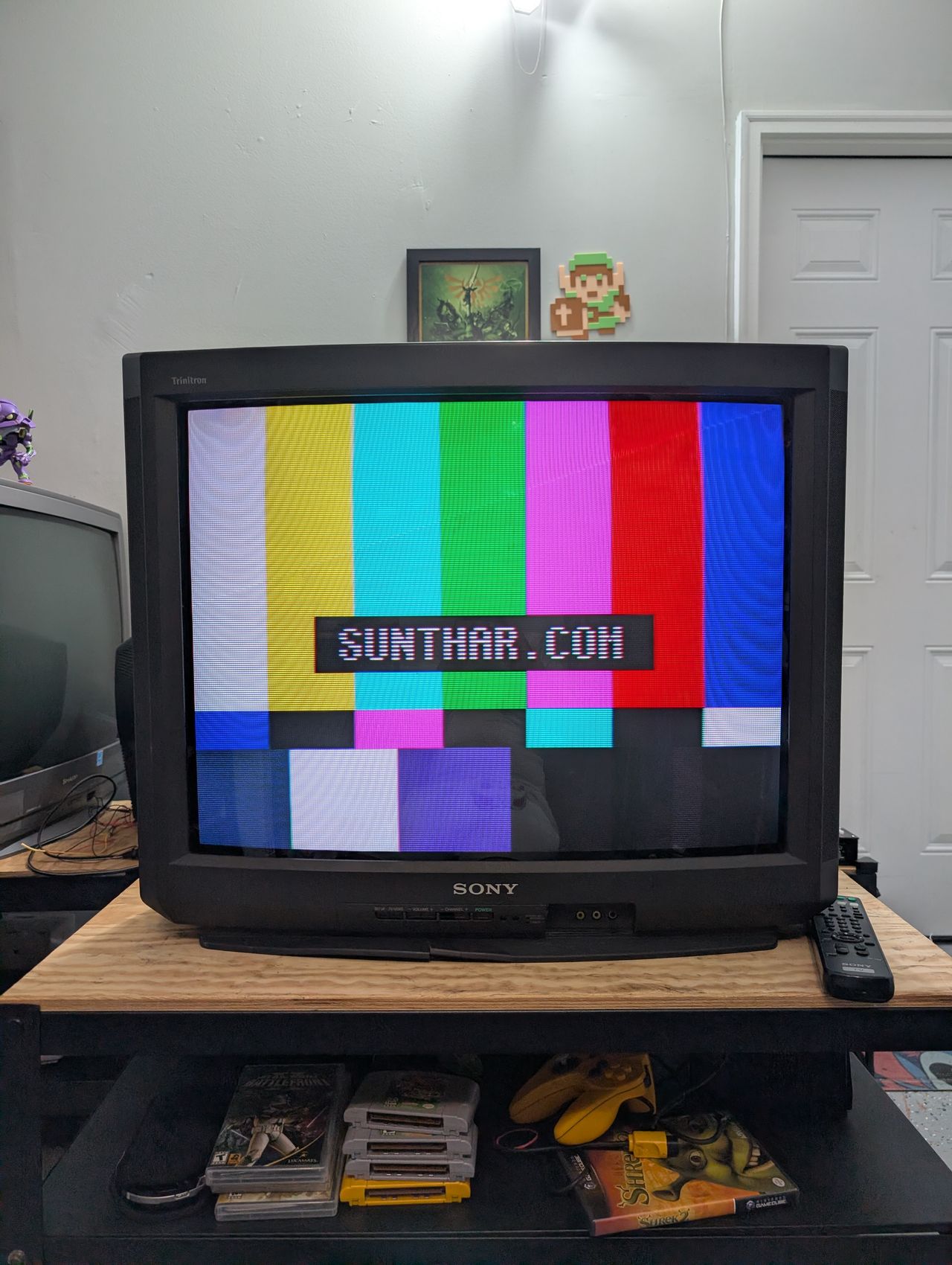
Set
Pictures
Photos by Sunthar
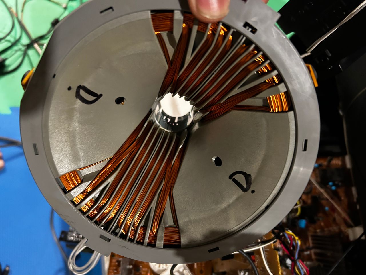
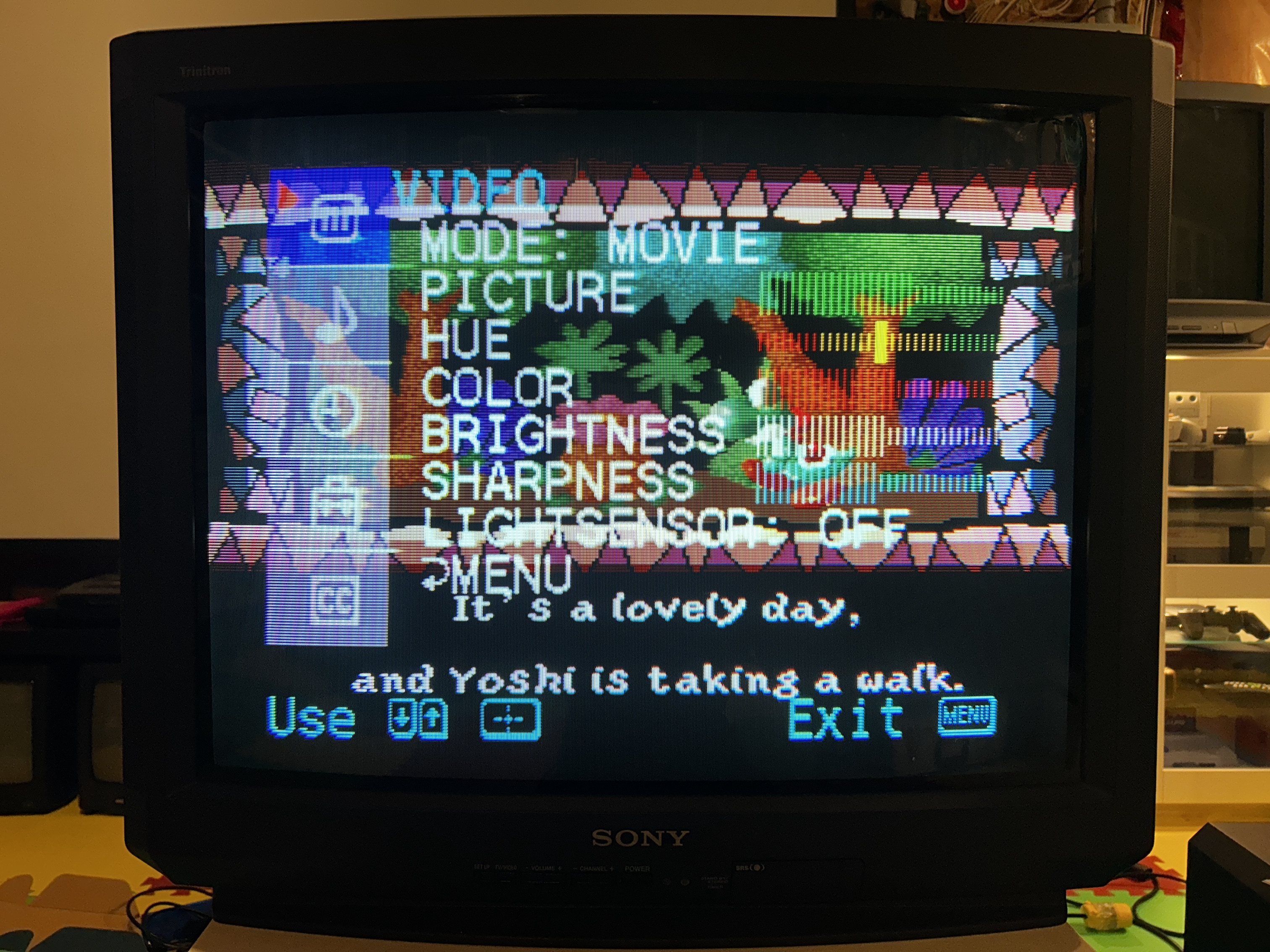
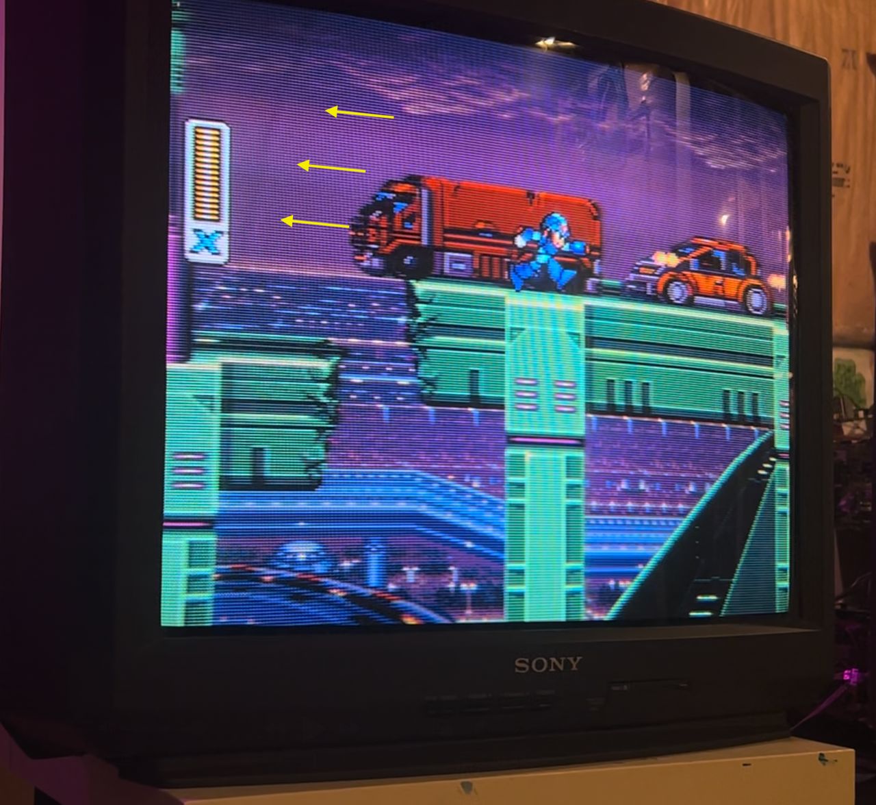
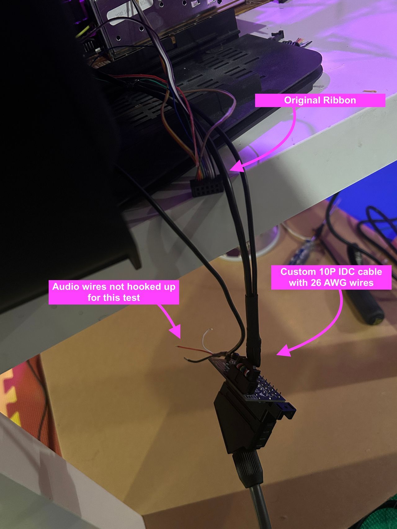
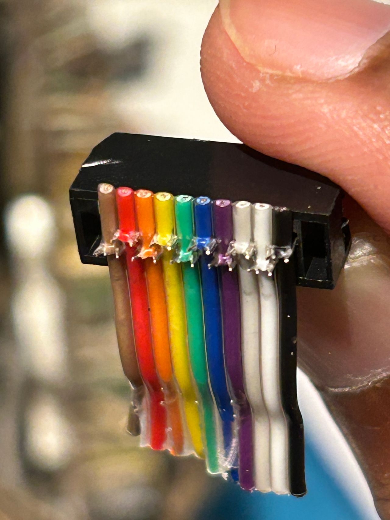
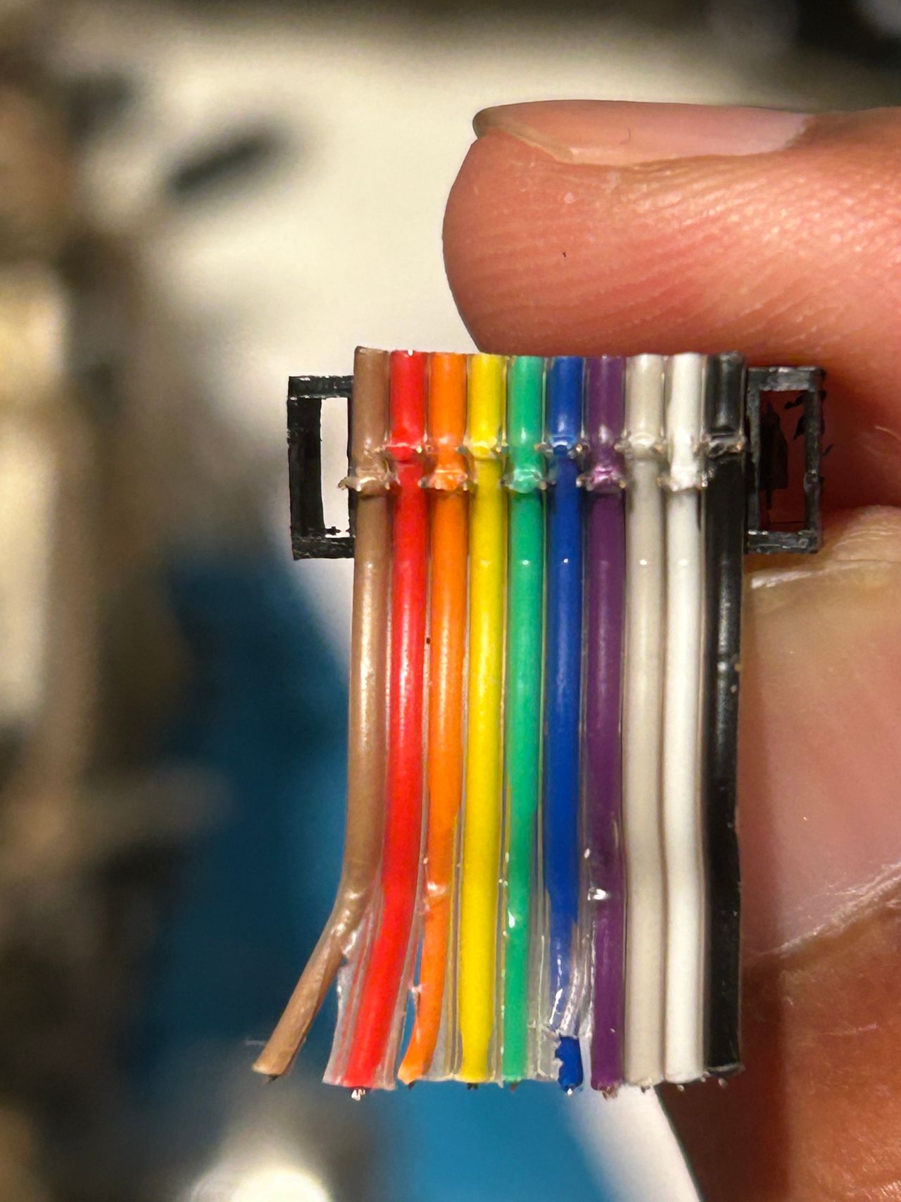
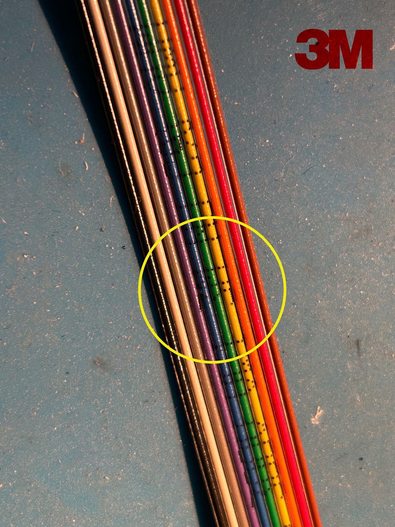
After years of assuming the circular jailbar issue was a CRT design flaw, finally discovered it was actually caused by the standard 28 AWG IDC ribbon cable. Switching to a thicker 26 AWG cable completely eliminated the interference.
Photos by Michael Lopez

Reference Photos