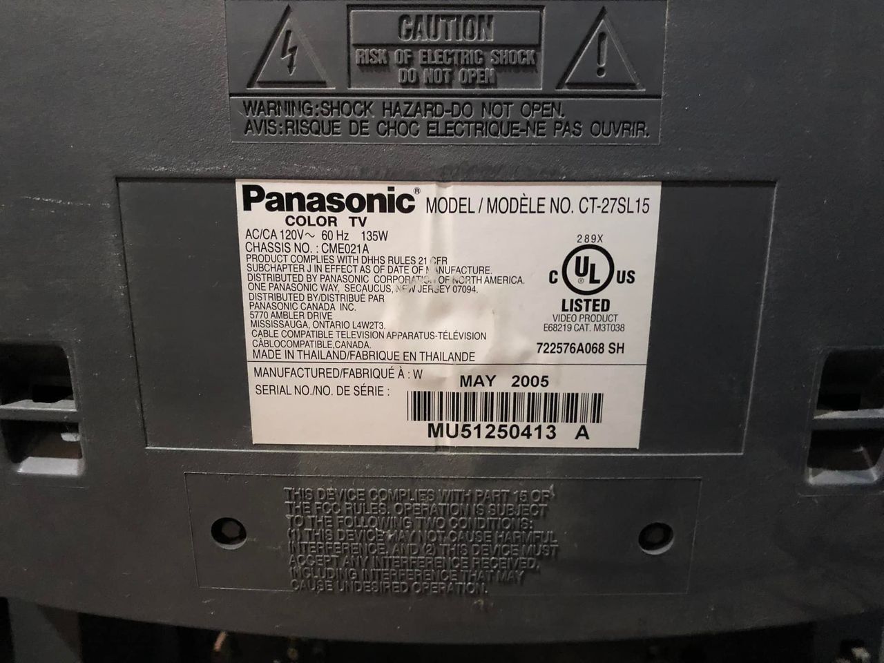
Panasonic CT-27SL15
Panasonic CT-27SL15 CRT RGB mod
The Panasonic CT-27SL15 is a 27" Tau series flat-tube CRT television from 2005, often noted for excellent picture quality (similar to the Toshiba 27AF45) and a strong, bassy audio output. It features component, S-video, and composite inputs. It has forced velocity modulation that often requires physical disconnection for optimal, sharp 240p display.
This set is RGB modifiable.
View full CRT details and more mod examples →
Other than the fact the resistor values are slightly different the RGB mod should be similar to Toshiba 27AF45
Contributors
Thank you to everyone who contributed to this guide:
CRT safety
Caution
You can die doing this! So read carefully! CRT TV is not a toy. Do not open a CRT TV. If you don't have any prior knowledge about handling high voltage devices, this guide is not for you. CRT TV contains high enough voltage (20,000+ V) and current to be deadly, even when it is turned off.
Plan of attack
Manuals and Datasheets
Specs
- Manufactured: Thailand (2005)
- Format: NTSC
- Chassis: CME021A
- Tube: Panasonic A68QCU770X66
- Jungle Chip: M61283BFP
- OSD Chip: OEC7123A
- Screen Size: 27"
- Inputs: Composite, S-Video, RF, Component YPbPr
RGB mux diagram
Prepare the mux diagram. If you are building your own circuit, this diagram should help.
Performing the mod
Other than the fact the resistor values are slightly different the RGB mod should be similar to Toshiba 27AF45
STEP 1: Remove the following components
Remove RGB resistors to ground
- R141 (560Ω)
- R142 (560Ω)
- R143 (560Ω)
STEP 2: Disable VM (optional)
You can easily disable by disconnecting the VM cable on the neck board.
STEP 3: Connect RGB and blanking wires
![]()
STEP 4: Connect Sync, Audio and Ground wire
Connect the SIGNAL, AUDIO RIGHT, AUDIO LEFT, GROUND wires 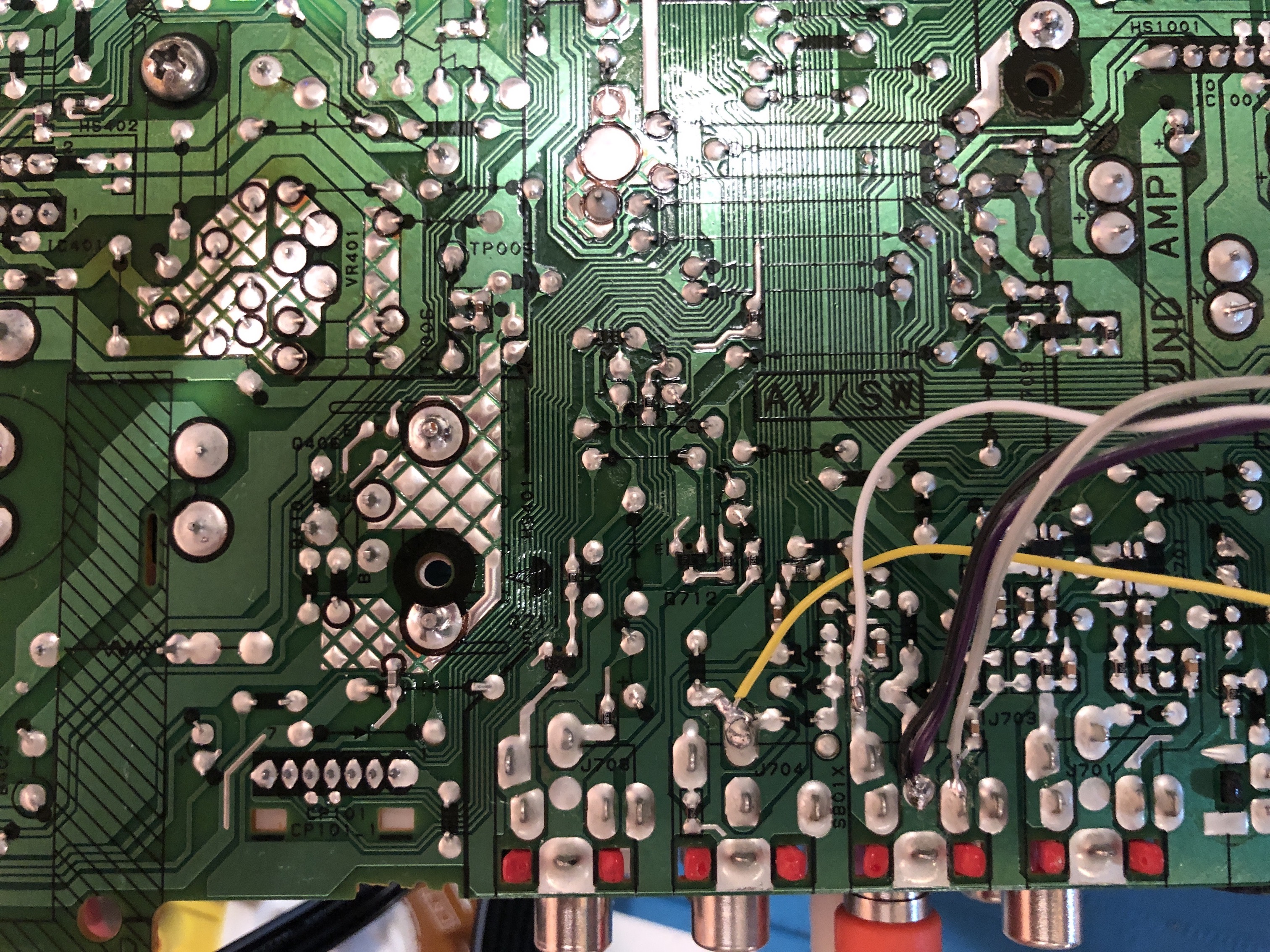
STEP 5: Build your mux board
This mod uses the RGB mux board. This is optional, but will make your mod easier and stable. You can also create the circuit presented in the schematics above without the board. Please also checkout the mux calculator to play with your own values.
| Component | Value |
|---|---|
| RGB/OSD inline resistor (chassis) | 2.7kΩ |
| Removed RGB/OSD resistor (chassis) | 560Ω |
| RGB termination (R1, R2, R3) | 75Ω |
| RGB inline (R4, R5, R6) | 470Ω |
| Audio LR (R7, R8) | 1kΩ |
| Diode (R9) | 1N4148 |
| Blanking Ground Resistor (R10) | open |
| Blanking Resistor (R11) | 0μF |
Compatible mux boards: RGB MUX BOARD KIT 1.4B
Pictures
Reference Photos