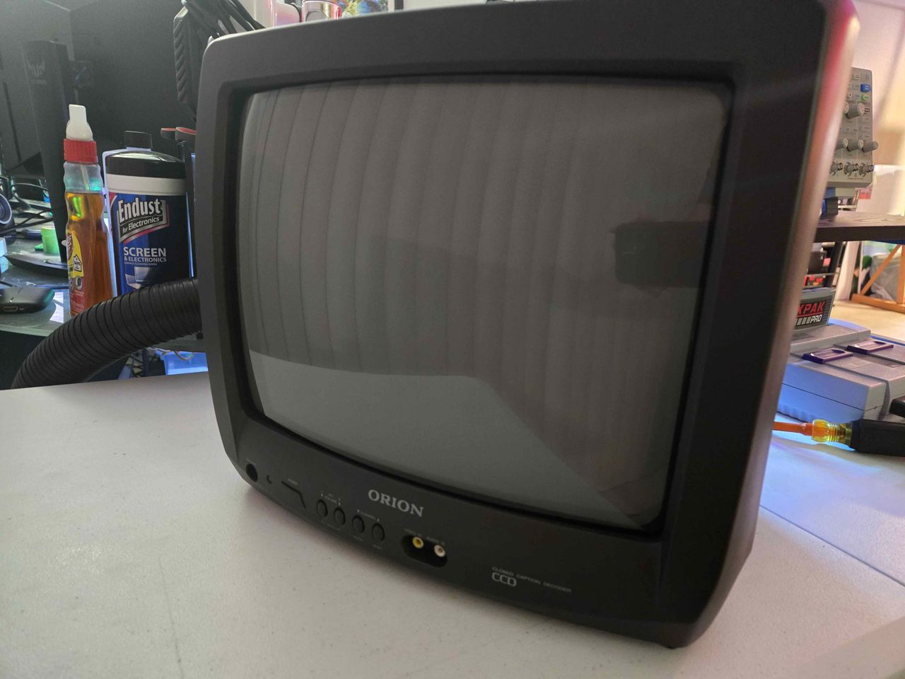
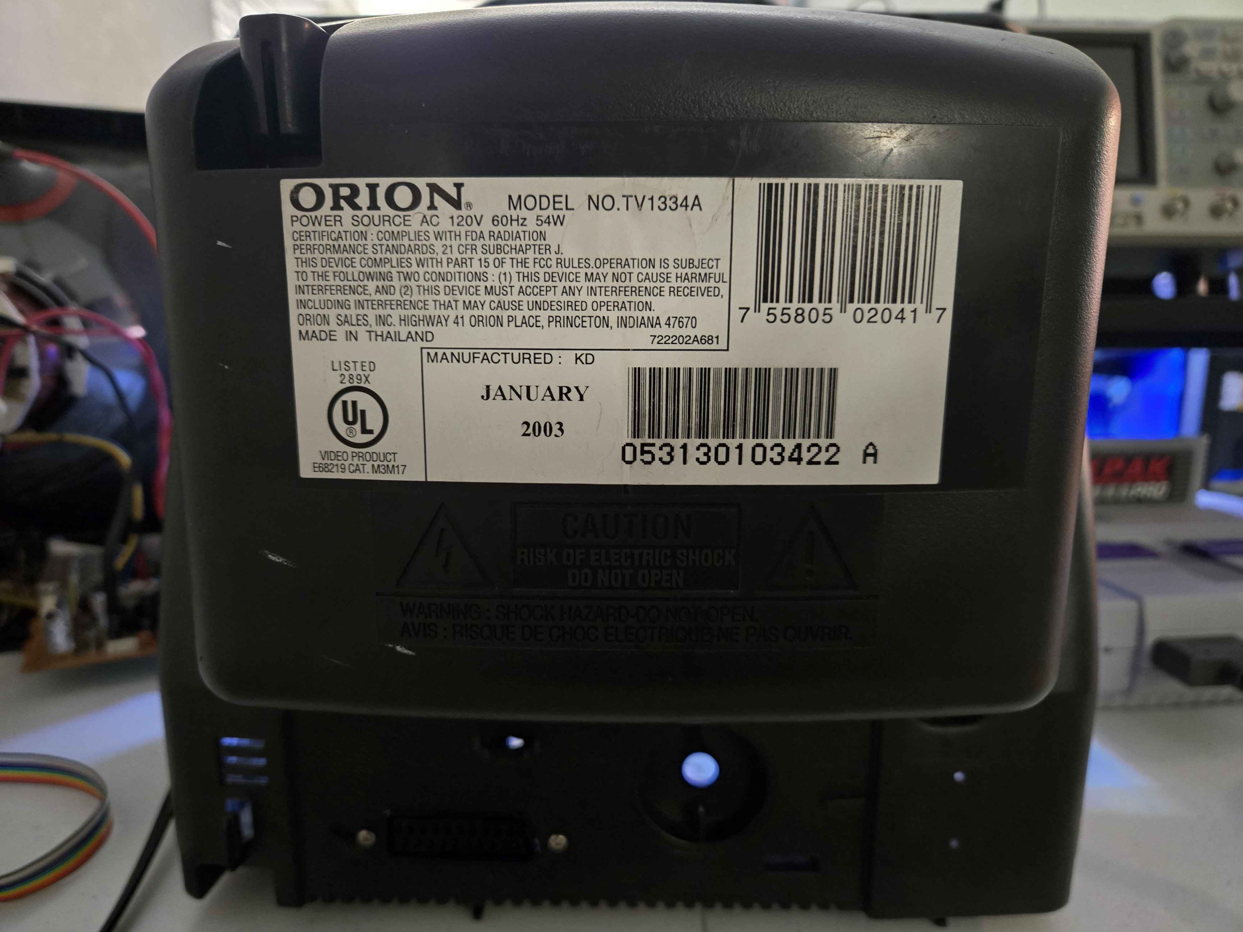
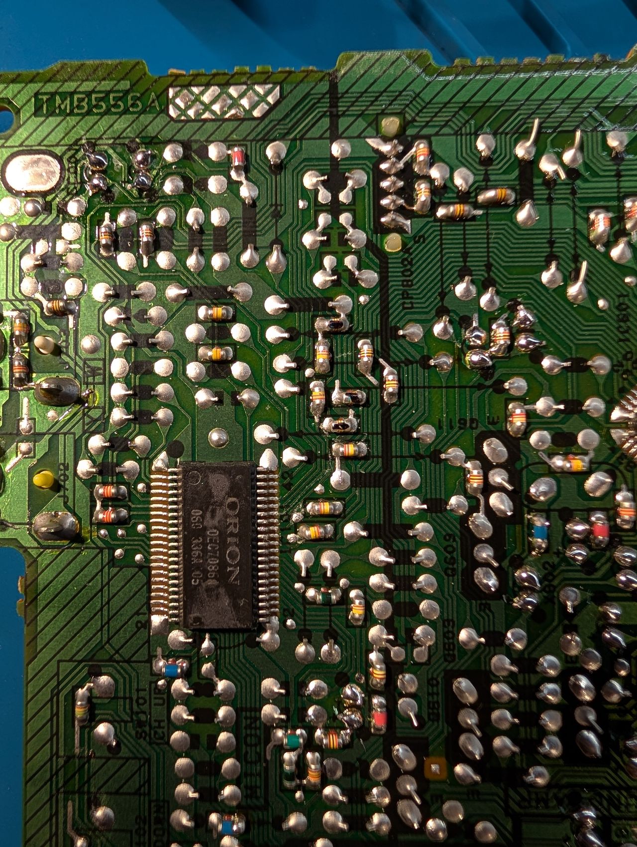
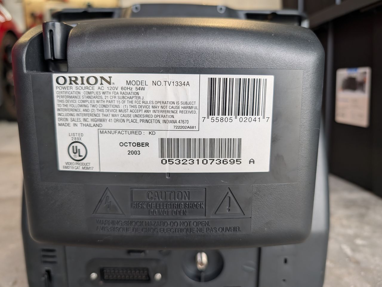
Orion TV1334A
Orion TV1334A CRT RGB mod
This tutorial covers the RGB mod for Orion TV1334A.
View full CRT details and more mod examples →
Contributors
Thank you to everyone who contributed to this guide:
- JT Lauro's Sector — photos
- G=Lock — contributor, Pictures and RGB mod
CRT safety
Caution
You can die doing this! So read carefully! CRT TV is not a toy. Do not open a CRT TV. If you don't have any prior knowledge about handling high voltage devices, this guide is not for you. CRT TV contains high enough voltage (20,000+ V) and current to be deadly, even when it is turned off.
Plan of attack
Service manuals
Specs
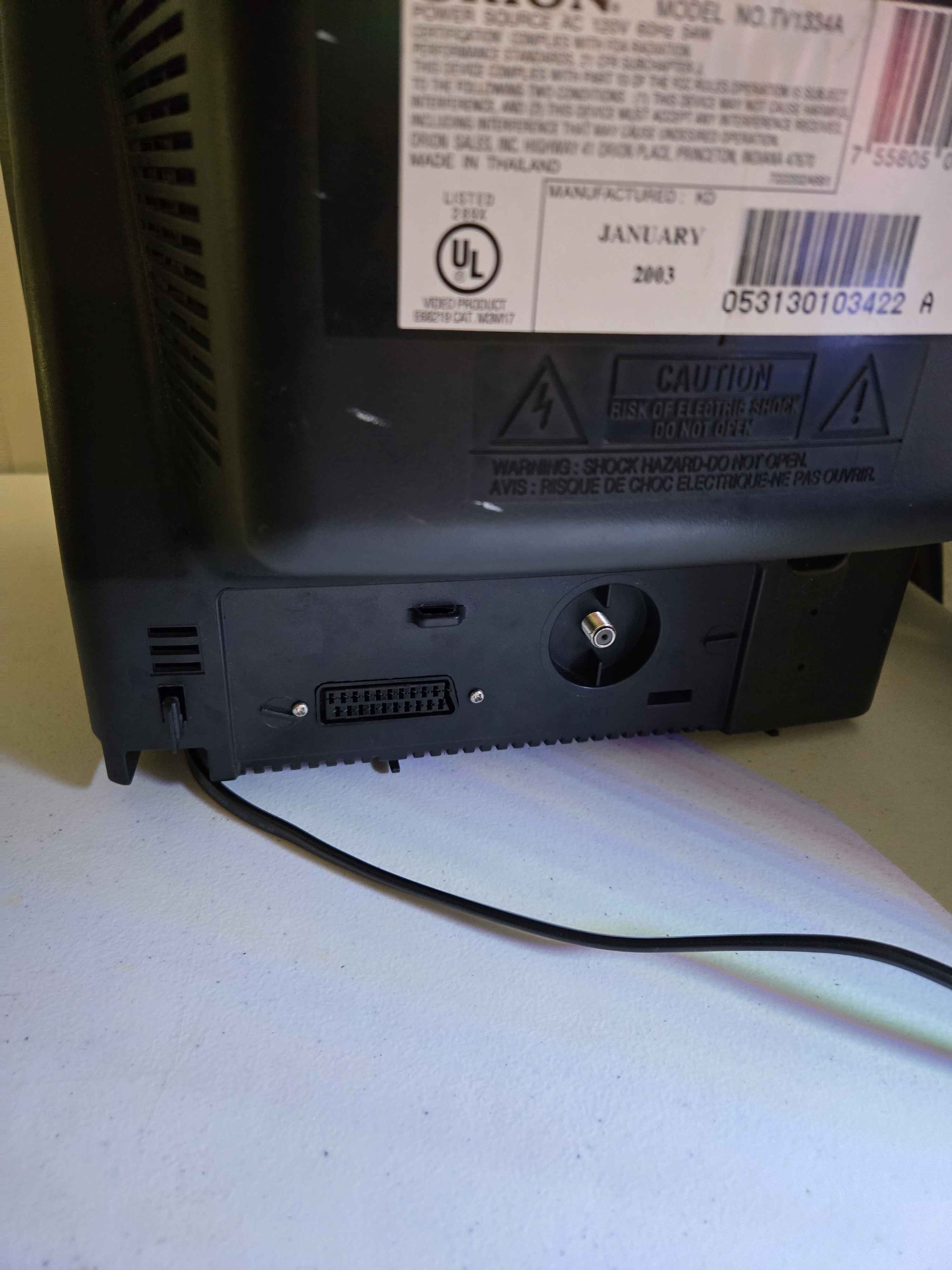
- Year: 2003
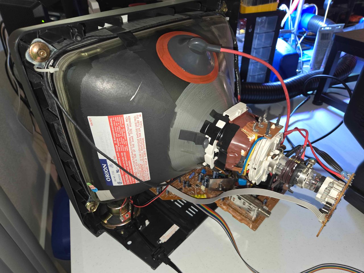
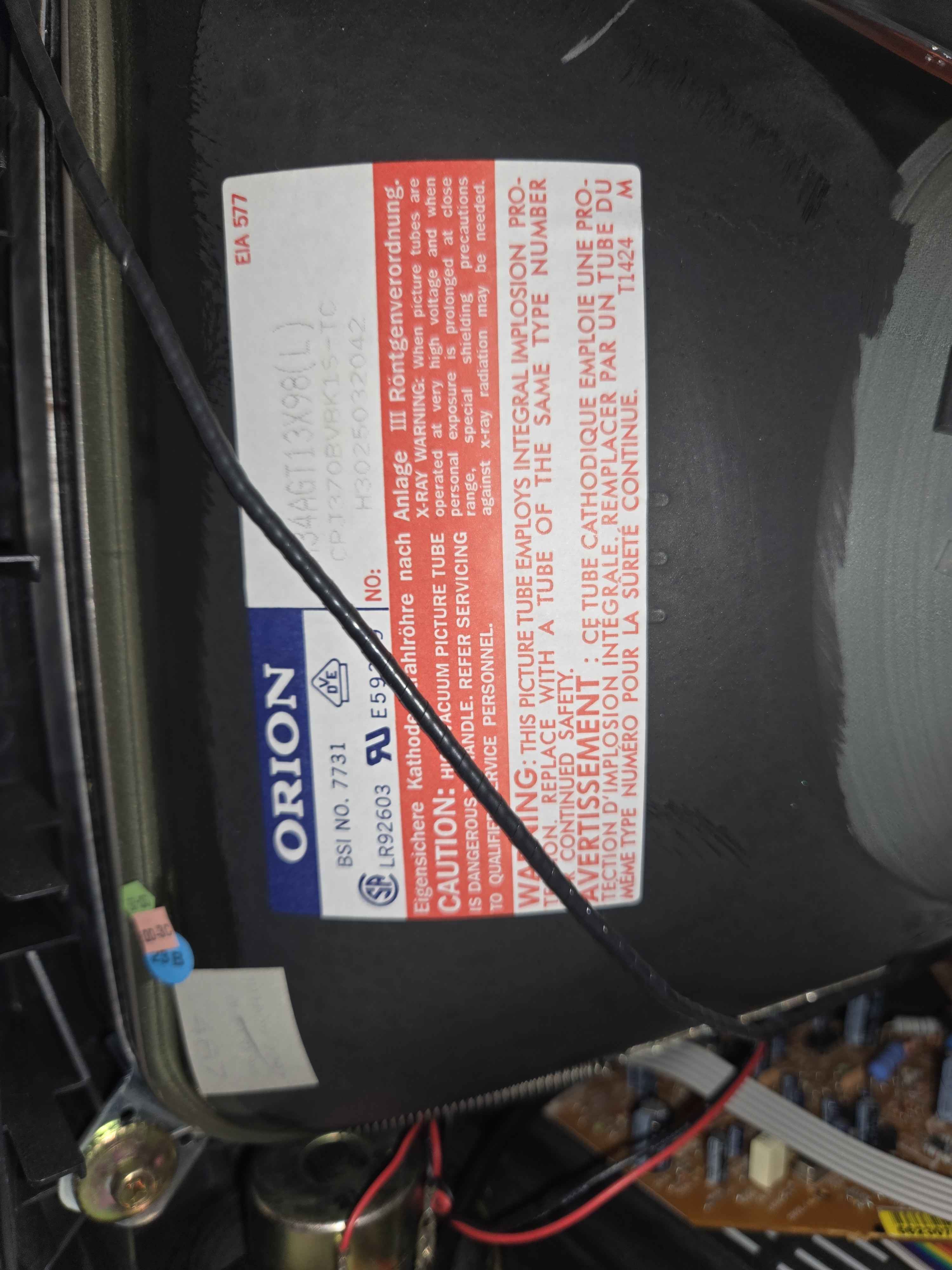
- Tube: Orion A34AGT13X98
- Jungle Chip: Renesas M61206FP
- OSD Chip: Orion OEC7073A
- Screen Size: 13"
RGB mux diagram
Performing the mod
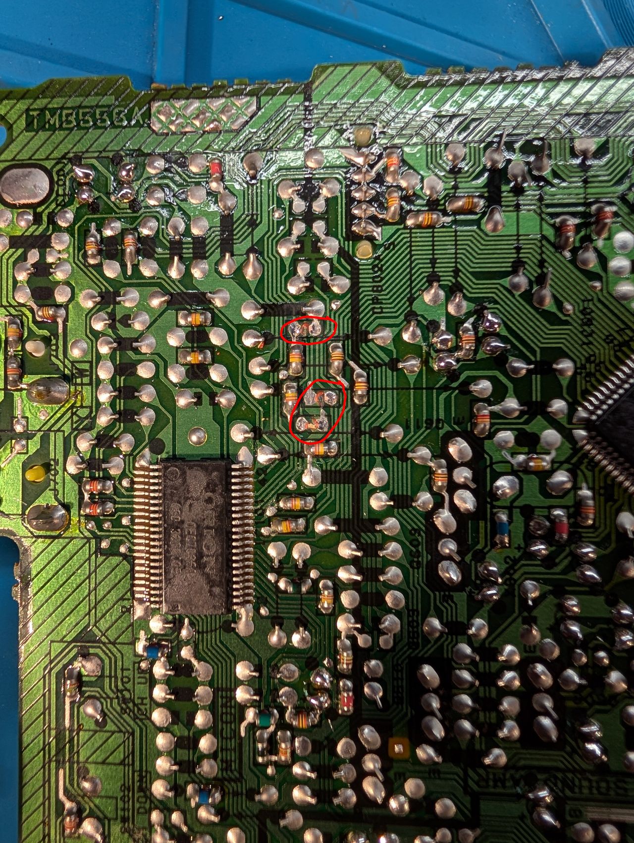
STEP 1: Remove the following components
Remove the three 680 ohm, RGB resistors to ground
- R102 (680Ω)
- R103 (680Ω)
- R104 (680Ω)
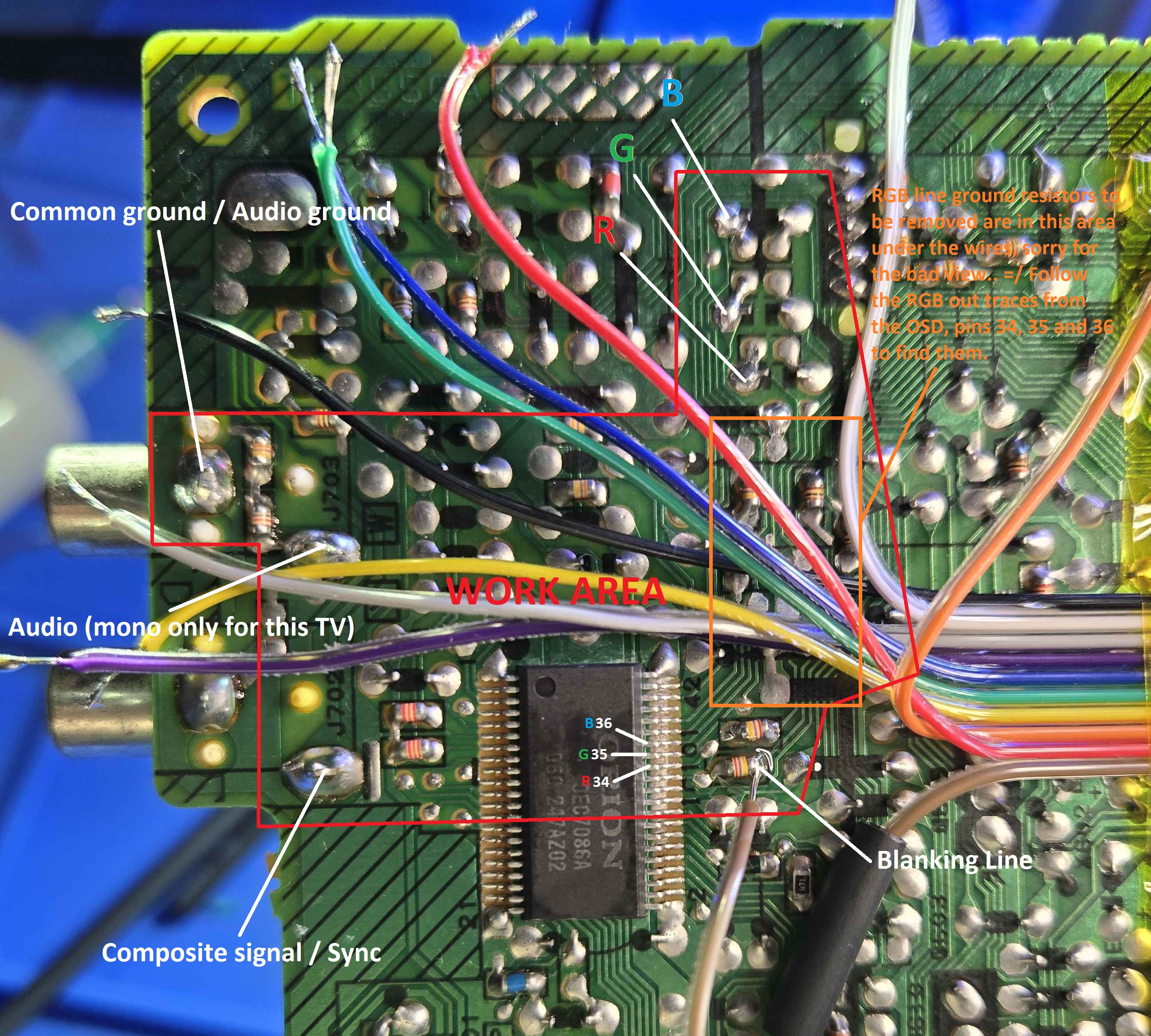
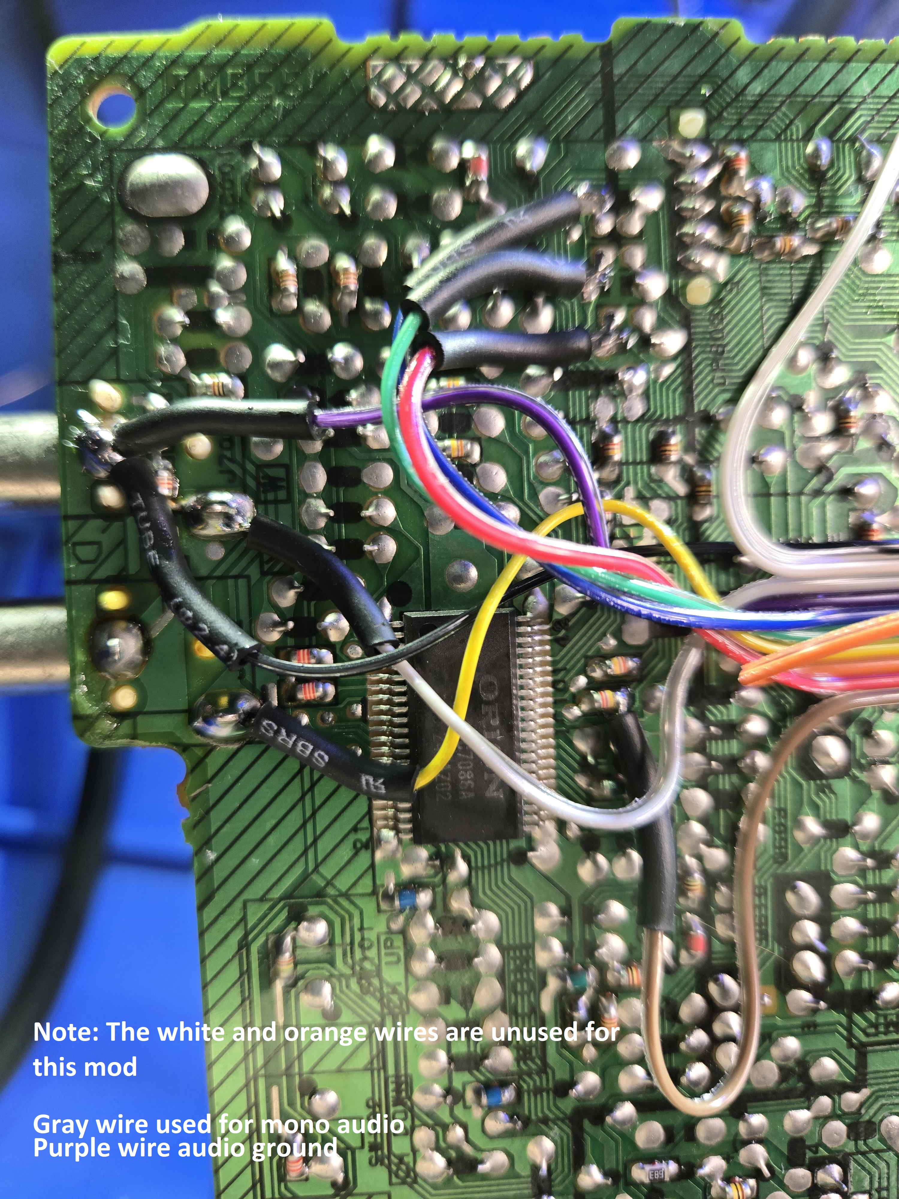
STEP 2: Connect RGBs, Blanking and Audio
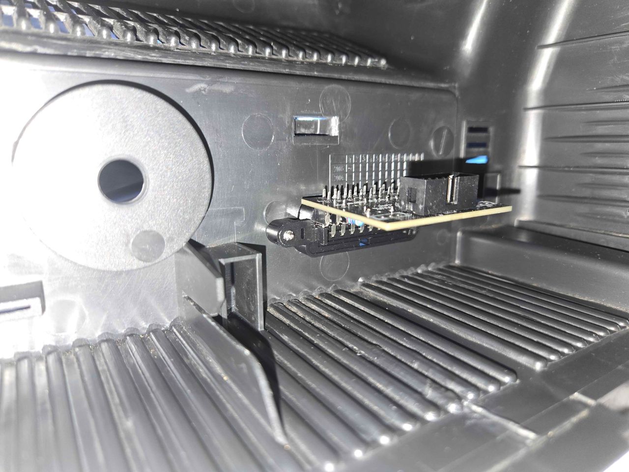
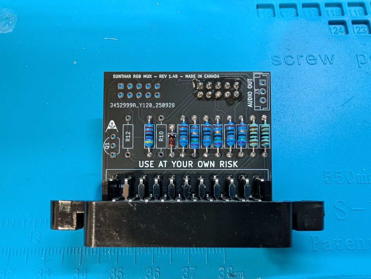
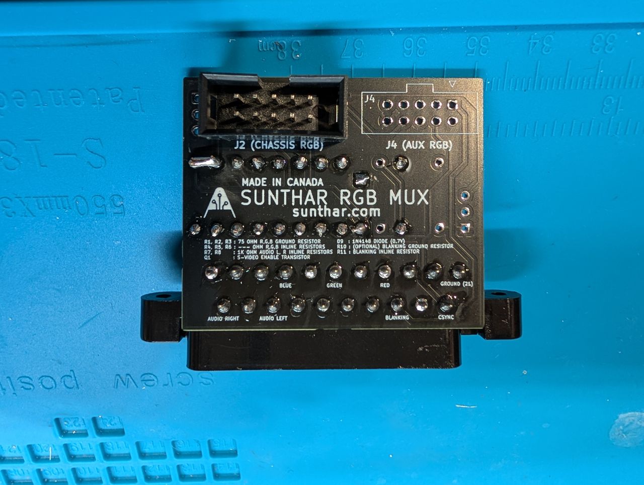
STEP 3: Build your mux circuit
This mod uses the RGB mux board. This is optional, but will make your mod easier and stable. You can also create the circuit presented in the schematics above without the board. Please also checkout the mux calculator to play with your own values.
| Component | Value |
|---|---|
| RGB/OSD inline resistor (chassis) | 4.7kΩ |
| Removed RGB/OSD resistor (chassis) | 680Ω |
| RGB inline diode method (chassis) | No |
| 0.1μF caps replaced (chassis) | No |
| RGB termination (R1, R2, R3) | 75Ω |
| RGB inline (R4, R5, R6) | 680Ω |
| Audio LR (R7, R8) | 1kΩ |
| Diode (R9) | 1N4148 |
| Blanking Ground Resistor (R10) | open |
| Blanking Resistor (R11) | 4.7kΩ |
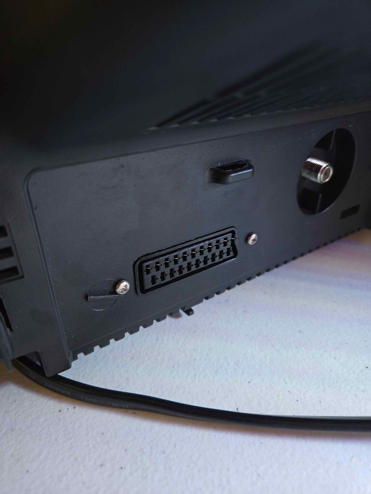
STEP 4: Attach the female SCART connector to TV
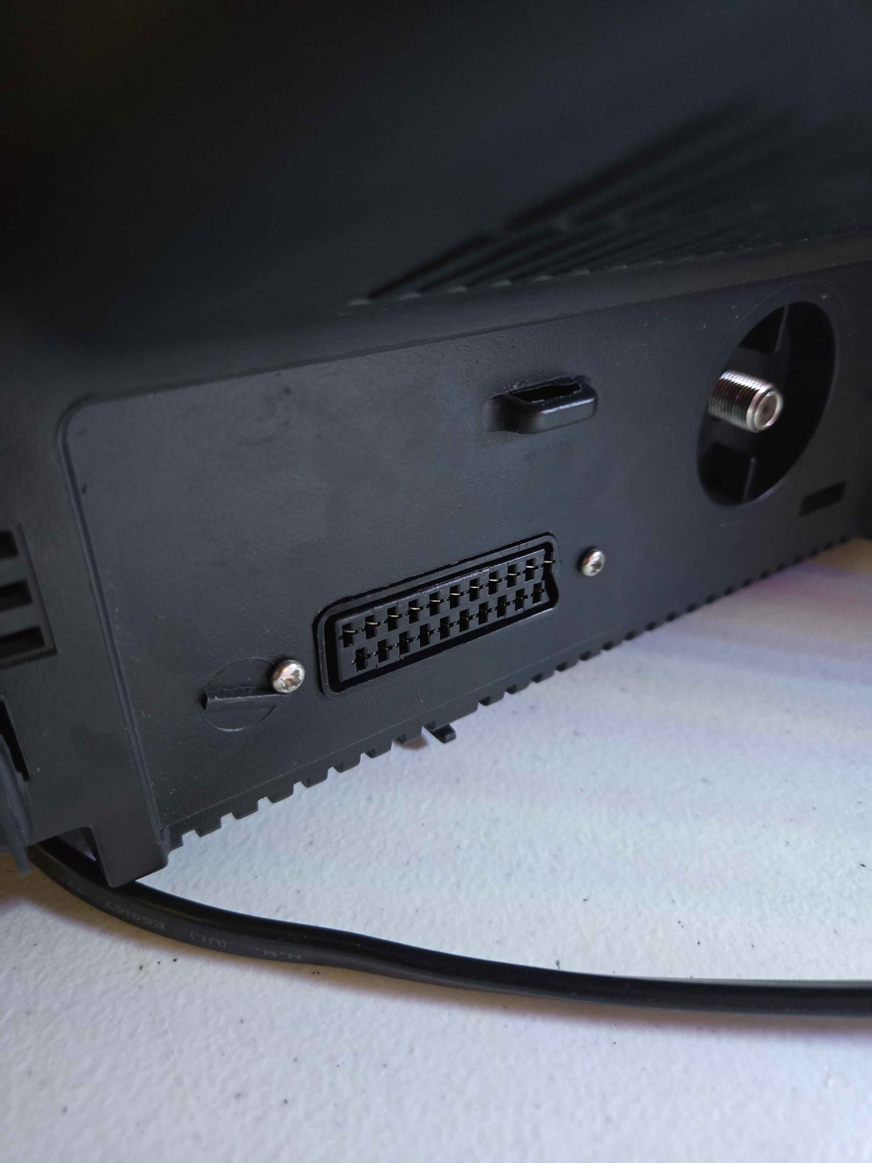
Creating a SCART cutout and mounting it is an art. I have a dedicated section for it.
How to create and mount a SCART female plug?
Pictures
Photos by JT Lauro's Sector
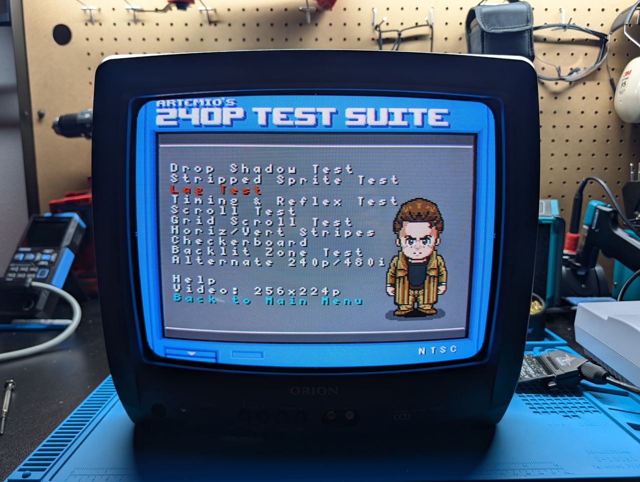
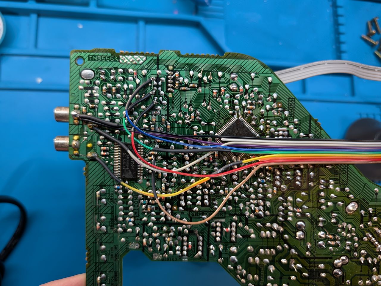
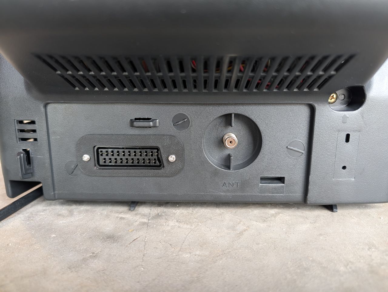
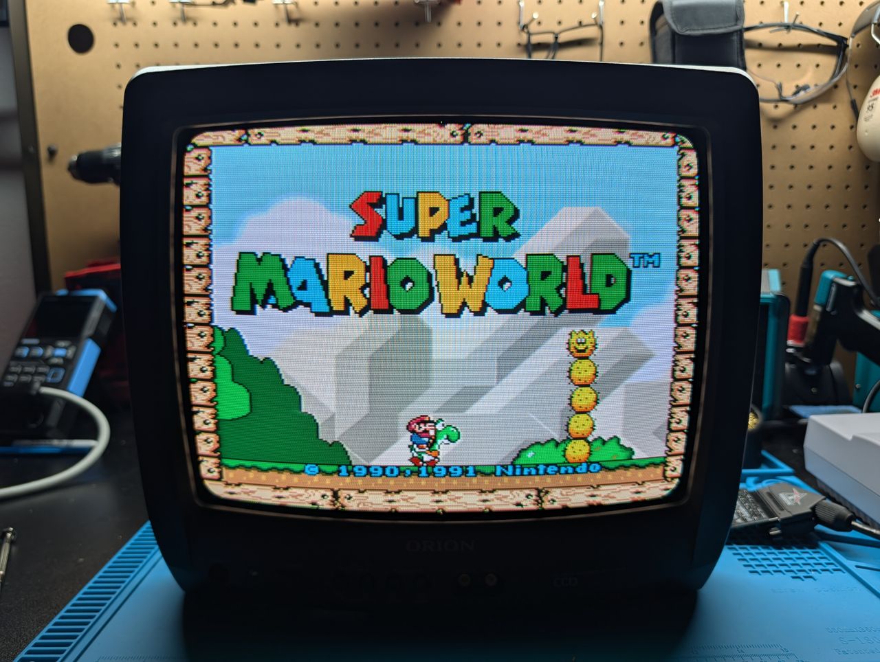
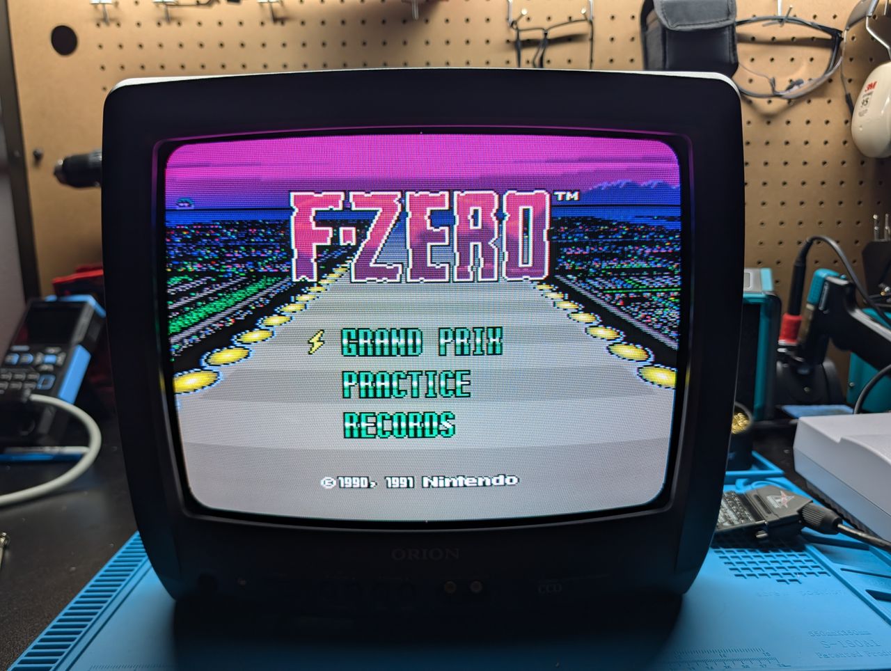
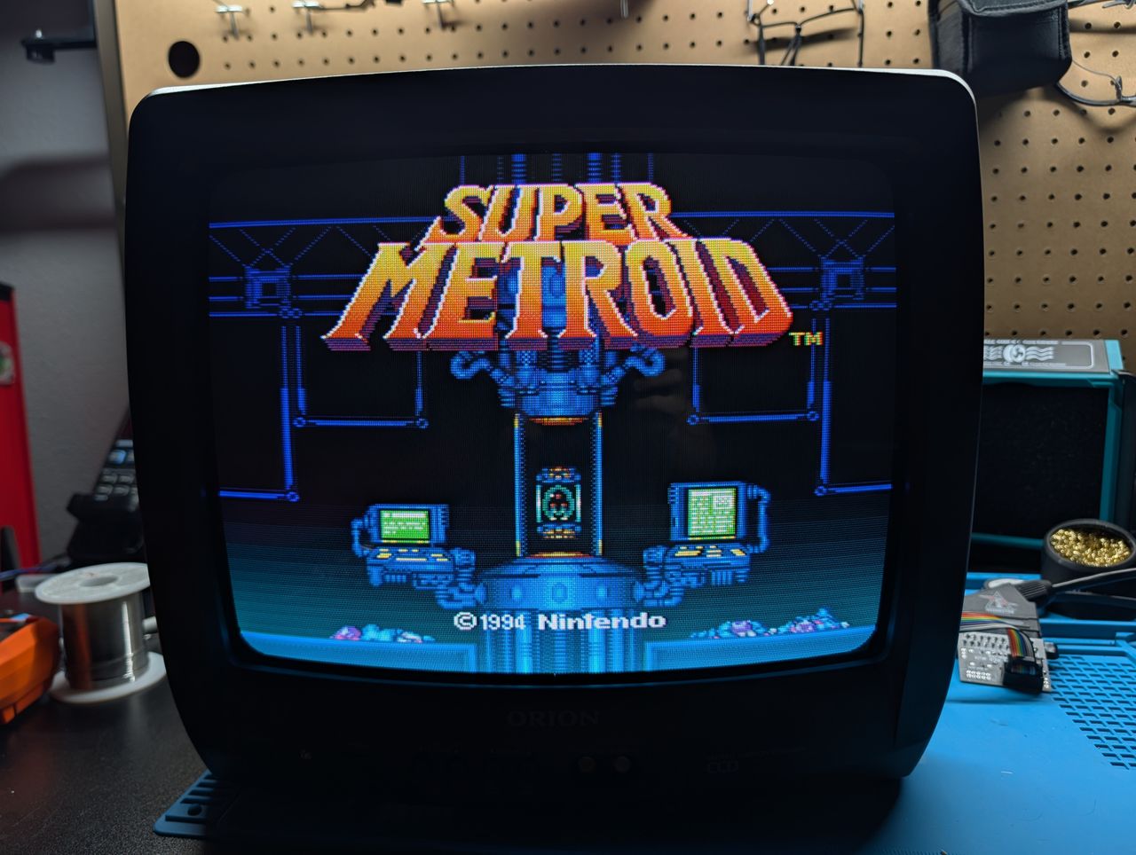
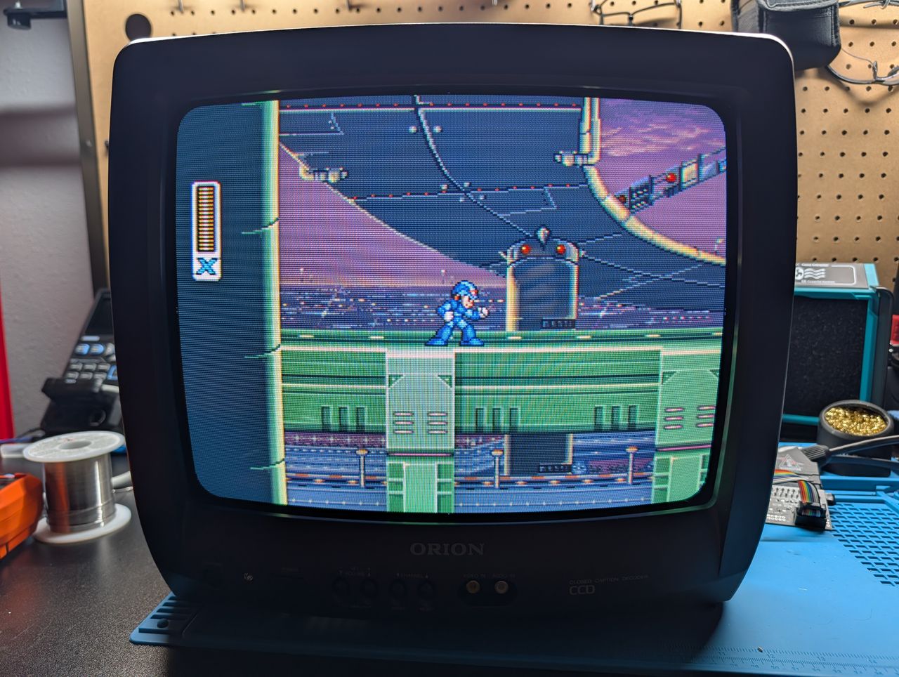
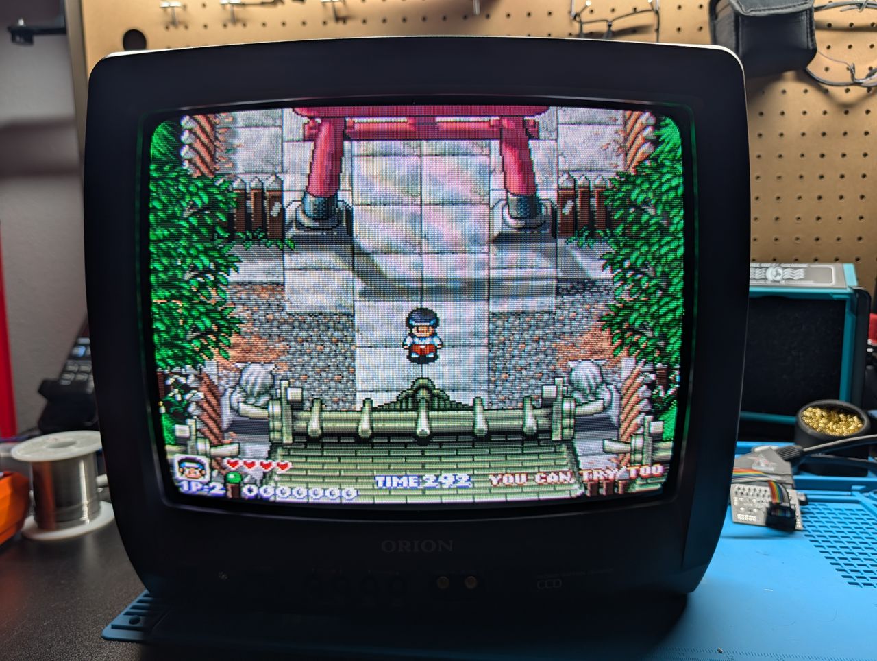

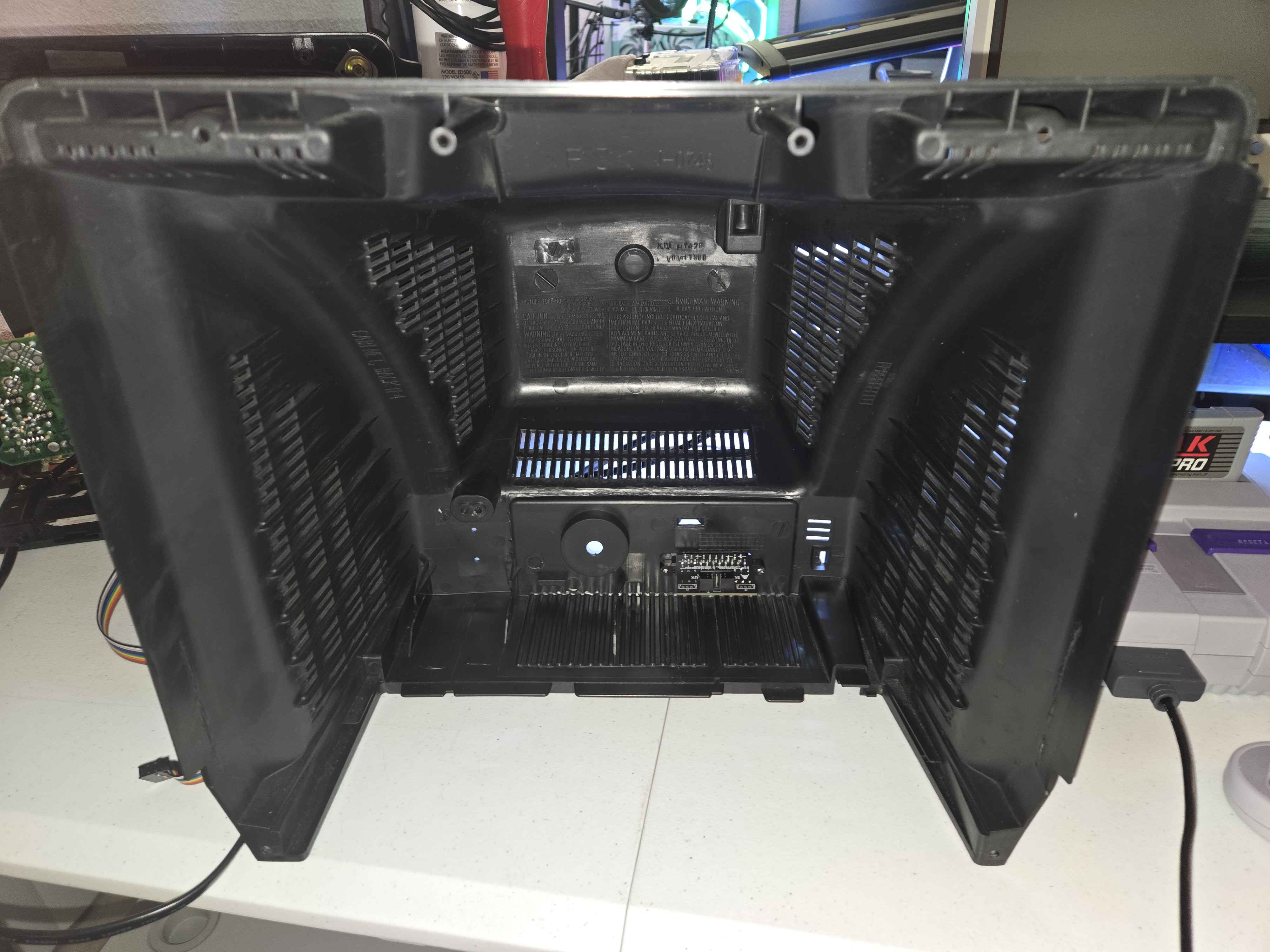
Reference Photos