Hitachi 36UX01S
Hitachi 36UX01S CRT RGB mod
I installed Sunthar's RGB mux mod in a 36" mid 2001 Hitachi set. The RGB provides more vibrant colors and sharper edges than the built in component on this set. I also disabled VM for svideo and composite inputs.

View full CRT details and more mod examples →
This mod should also work for other sets with TA1310N datasheet.
- Hitachi 36UX01S
- Hitachi 32UX01S
Contributors
Thank you to everyone who contributed to this guide:
- CrystalPixel's corner — photos and documentation
CRT safety
Caution
You can die doing this! So read carefully! CRT TV is not a toy. Do not open a CRT TV. If you don't have any prior knowledge about handling high voltage devices, this guide is not for you. CRT TV contains high enough voltage (20,000+ V) and current to be deadly, even when it is turned off.
Plan of attack
Manuals and Datasheets
Specs
- Year:
- Chassis: M10LXU
- Tube: Hitachi A90AHH50X01
- Jungle Chip: Toshiba TA1310N
- Screen Size: 36"
RGB mux diagram
TA1310N has two sets of analog RGB inputs. One set is used for PiP (Picture In Picture) functionality. The other is used for Analog OSD input.
- R, G, B inputs via pins 3, 4, 5 (blanking on pin 6) is used for PiP. This input supports the standard 0.5Vpp analog signal input.
- R, G, B inputs via pins 7, 8, 9 (blanking on pin 10) is used for OSD. This input supports 1.25Vpp analog singal input.
Although it's theoretically possible to mux mod using the 7, 8, and 9 OSD inputs, doing so may result in a dull image if the voltage levels don’t match the chroma chip’s expectations. For better results, it's strongly recommended to use the PiP circuitry instead. While muxing with PiP might work, to keep things simpler and avoid complications, it's best to completely disconnect the PiP circuitry and directly inject the RGB signals.
Performing the mod
STEP 1: Disconnect PiP circuitry
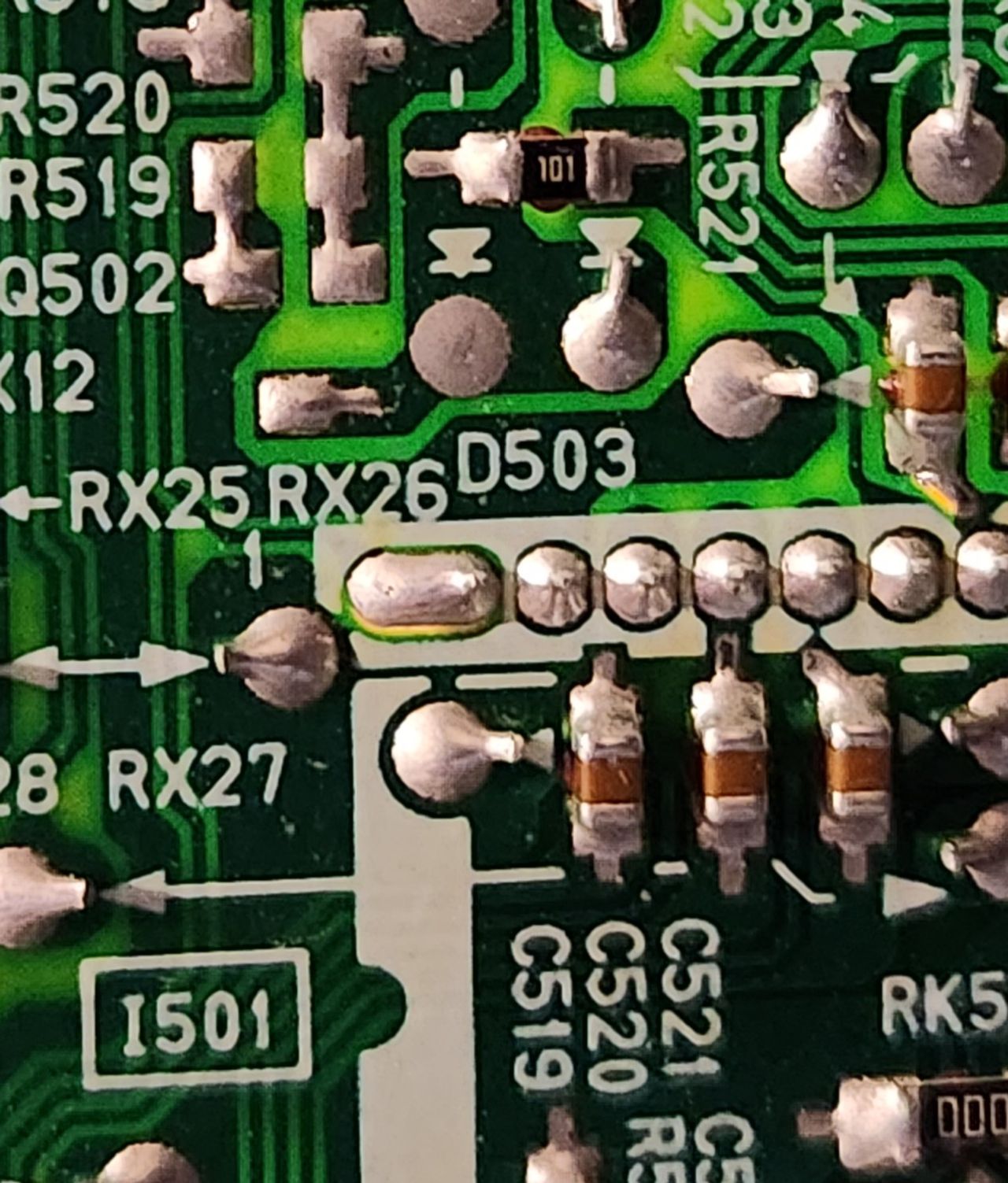
Close up of R521 and C519, C520, and C521. These components need to be removed to inject RGB into the PiP lines.
After de-soldering components, these are the pads I used to inject RGB and blanking. RGB is pins 2-4 respectively. The blanking line connects to pin 5 on the chip, but I found it easier to use R521's pad since it needs to be removed anyway.
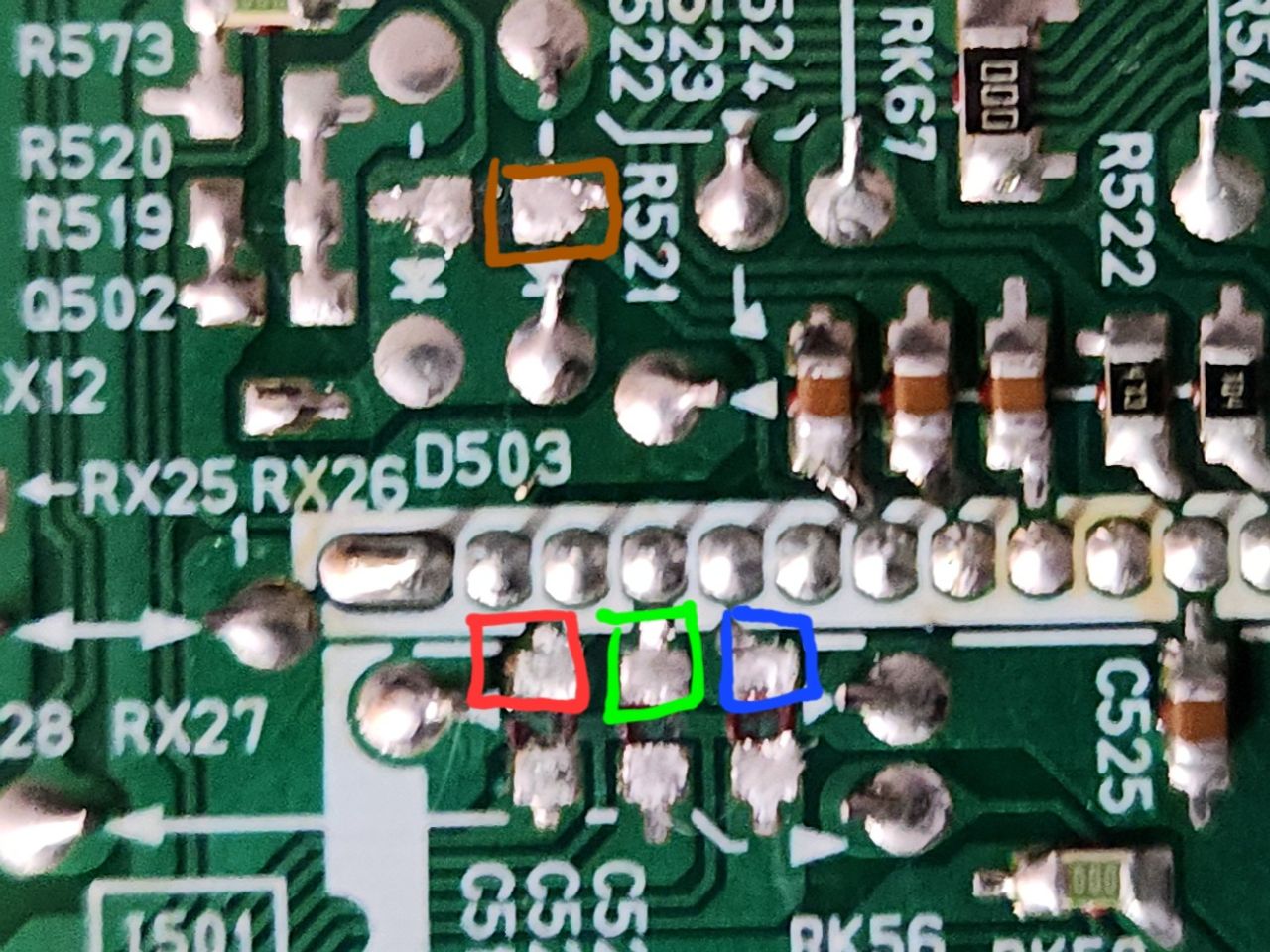
On a set without PiP (see 36GX01B), these pins should still be available to solder to since they share the same jungle chip.
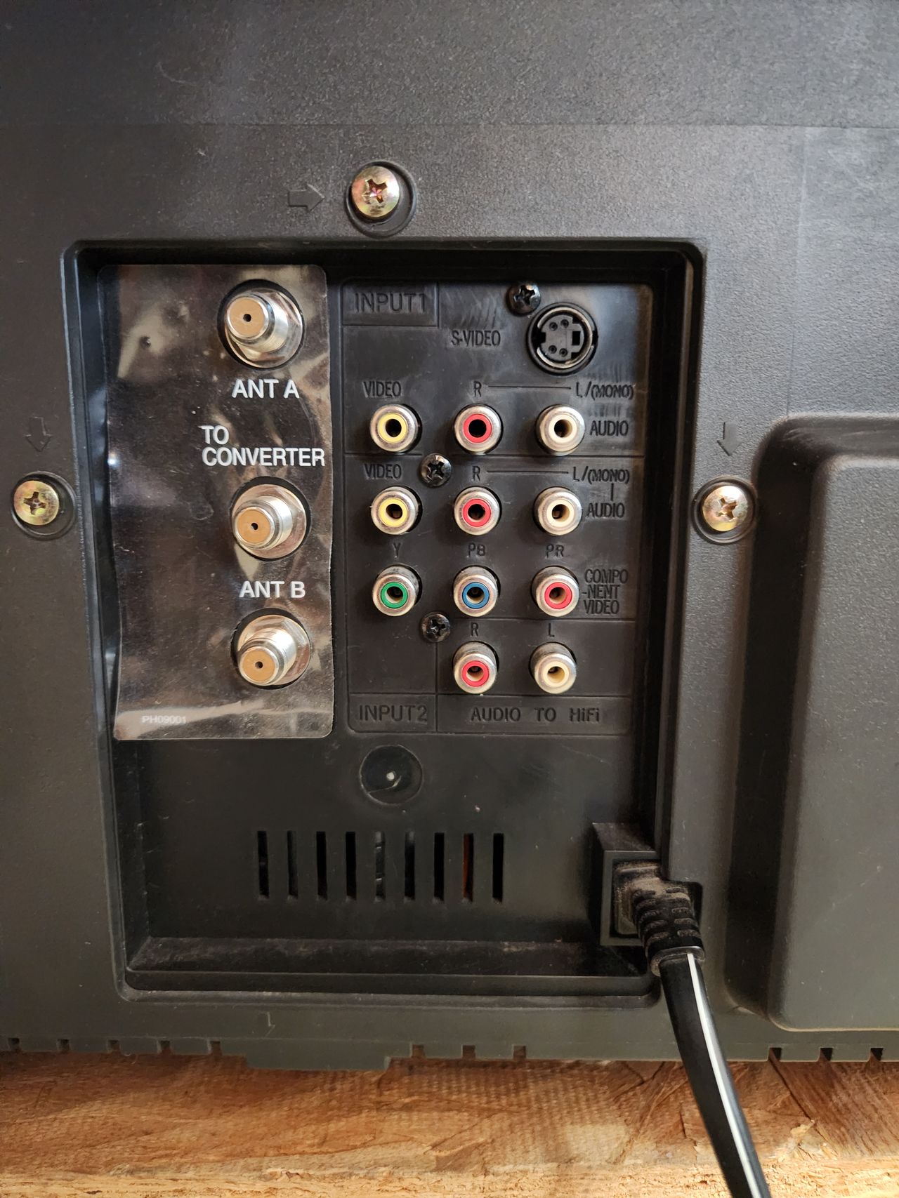
STEP 2: Attach R, G, B, blanking, audio, sync and ground wires
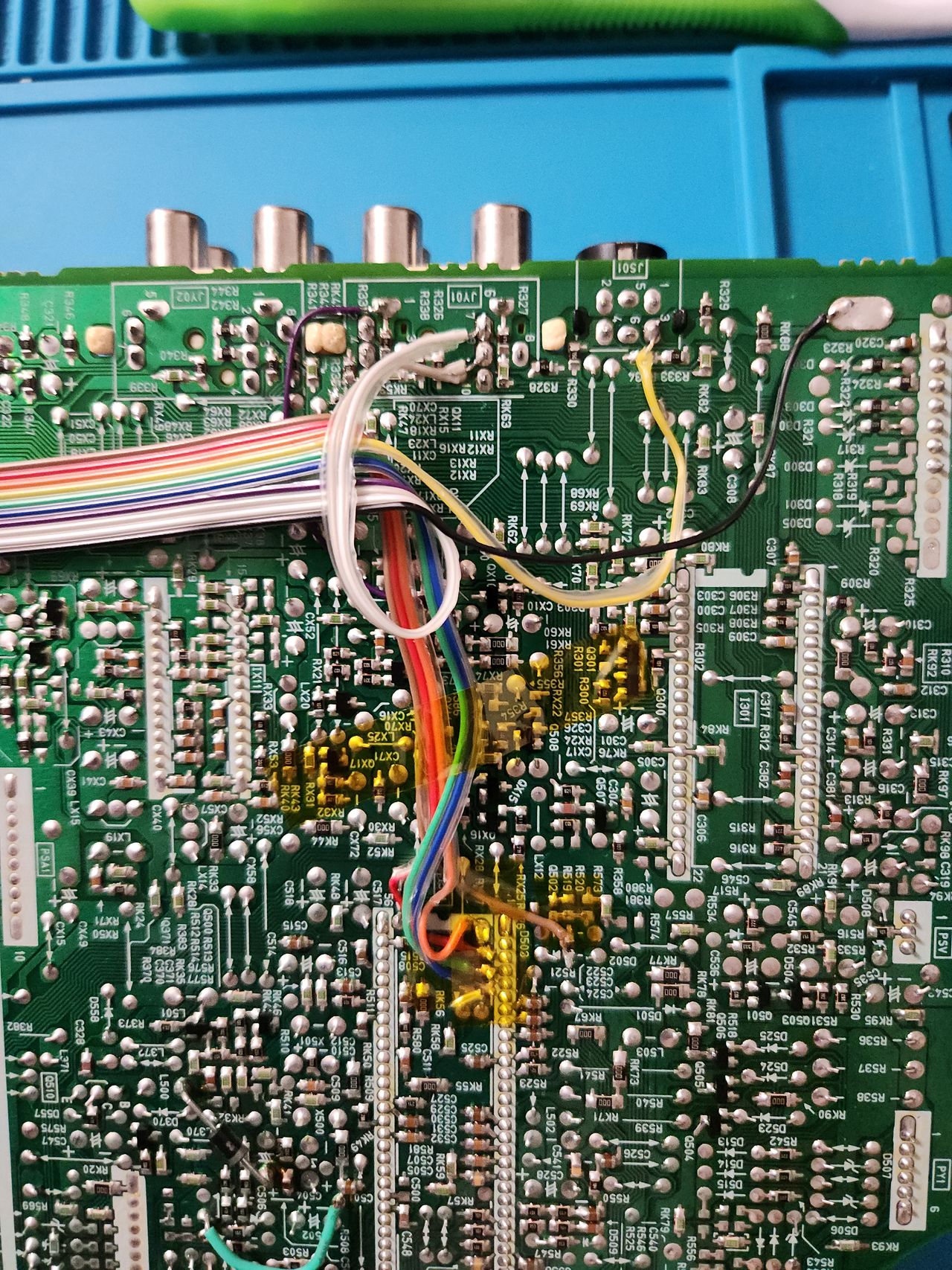
Here is the full wiring on the signal board. All wire colors correspond to Sunthar's IDC key for the mux mod. Note that I wired CSYNC to svideo pin 3 because I am using that input instead of composite. This set disables composite sync in favor of svideo when a cable is plugged in. However, if the svideo cable is unplugged, the injected RGB picture will destabilize as CSYNC is effectively disconnected.
If you are planning on using the composite input for some reason, solder CSYNC to that instead. It is labelled pin 10 next to the white audio L and R wires.
In the future, I may add a switch on the back that lets me change between composite sync and svideo sync, but for now it works just fine.
STEP 3: Disconnect VM
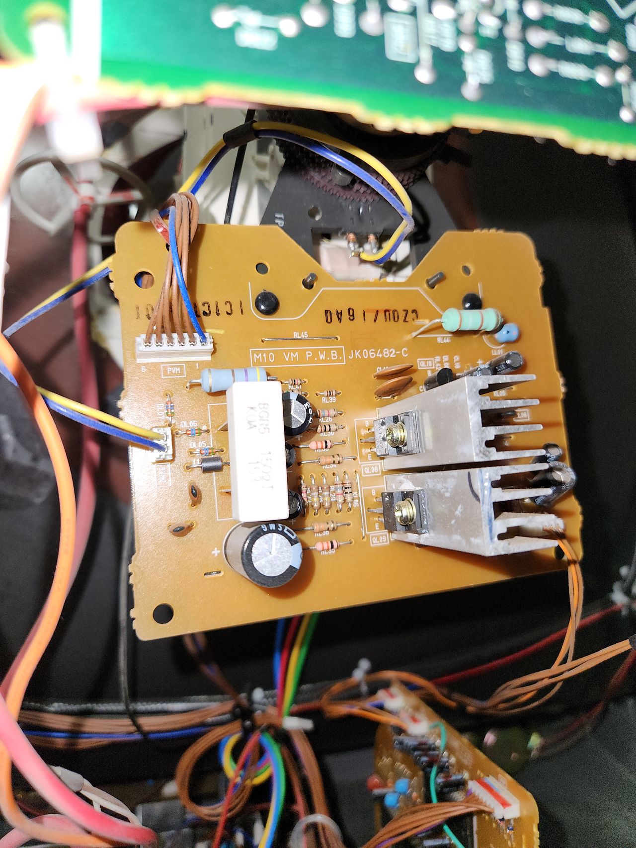
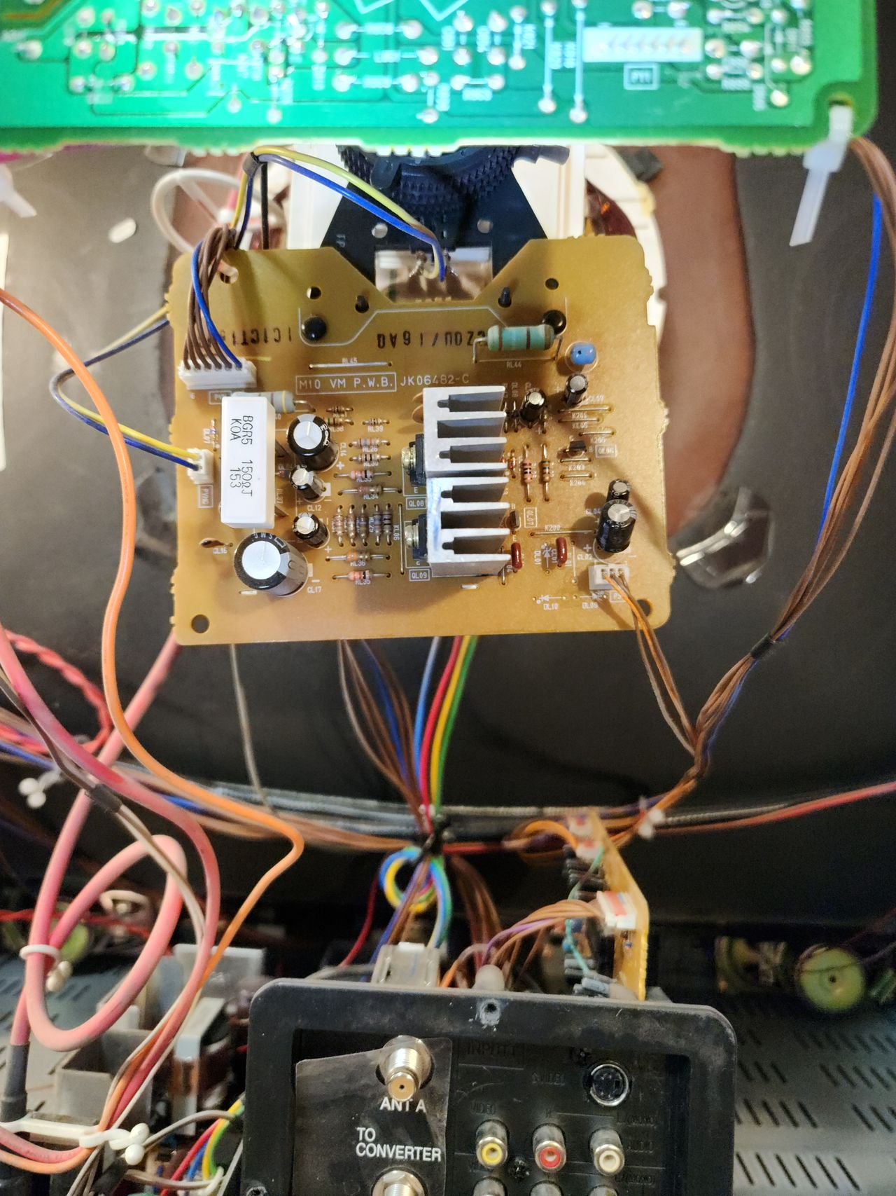
This board sits below the neck and controls VM. Disconnecting the top left wire with 5 brown and 1 blue will disable VM for this set.
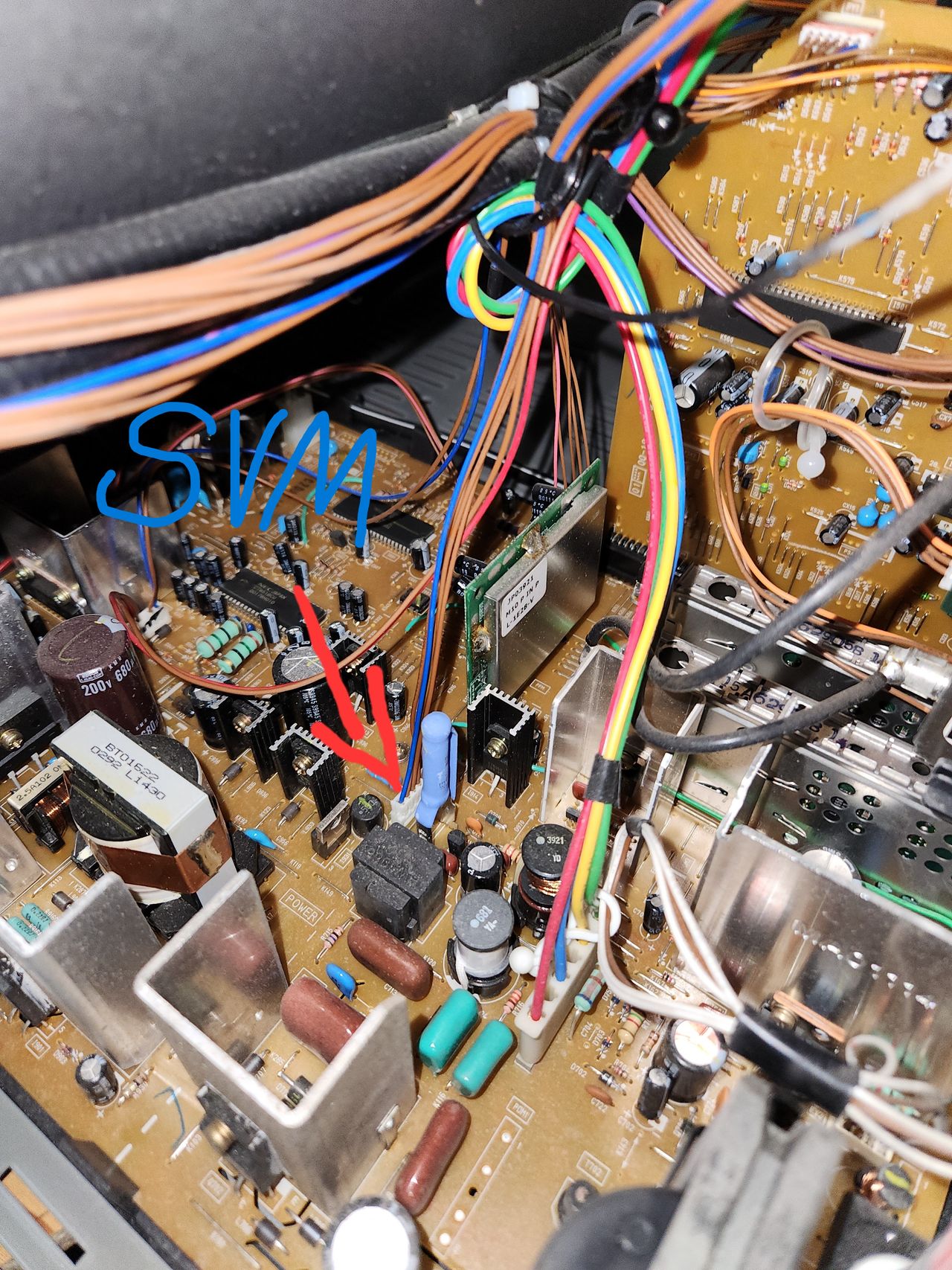
Here is where the VM wire connects to the main board if you prefer to disconnect it there. If your set has been on, the resistor with the blue heat shrink over it can be very hot, so please be careful disconnecting the wire.
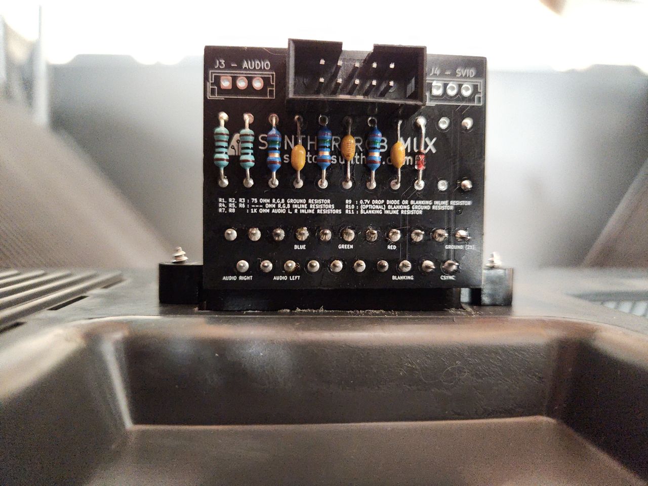
STEP 4: Build your mux board
This mod uses the RGB mux board. This is optional, but will make your mod easier and stable. You can also create the circuit presented in the schematics above without the board. Please also checkout the mux calculator to play with your own values.
| Component | Value |
|---|---|
| RGB/OSD inline resistor (chassis) | 4.7kΩ |
| Removed RGB/OSD resistor (chassis) | 1kΩ |
| RGB termination (R1, R2, R3) | 75Ω |
| Audio LR (R7, R8) | 1kΩ |
| Diode (R9) | 1N4148 |
| Blanking Ground Resistor (R10) | 1kΩ |
| Blanking Resistor (R11) | 1kΩ |
STEP 5: Mount the board
I mounted the connector here because it is on the opposite side as the flyback and lies right next to the jungle chip internally.
Pictures
Photos by CrystalPixel's corner
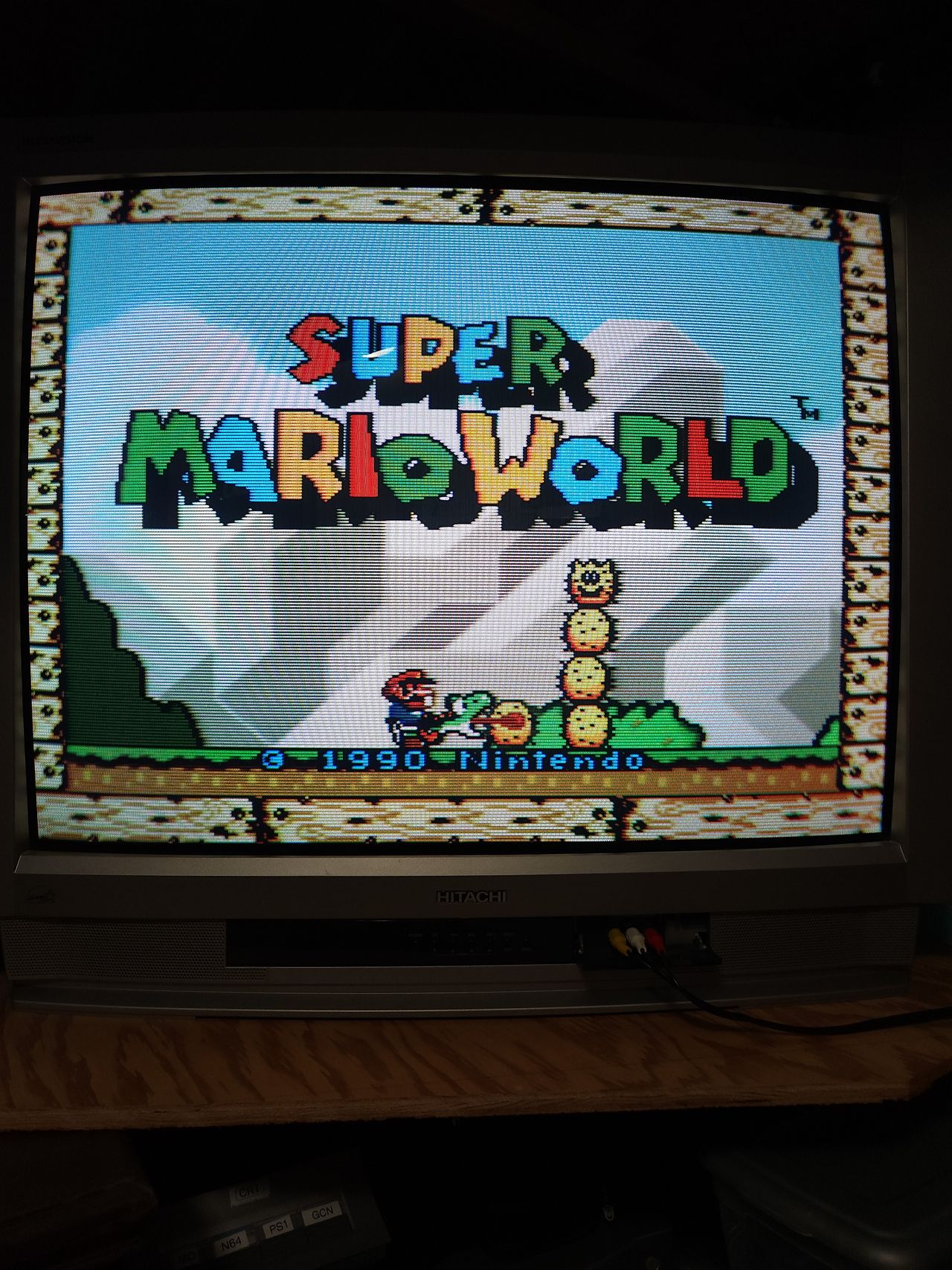
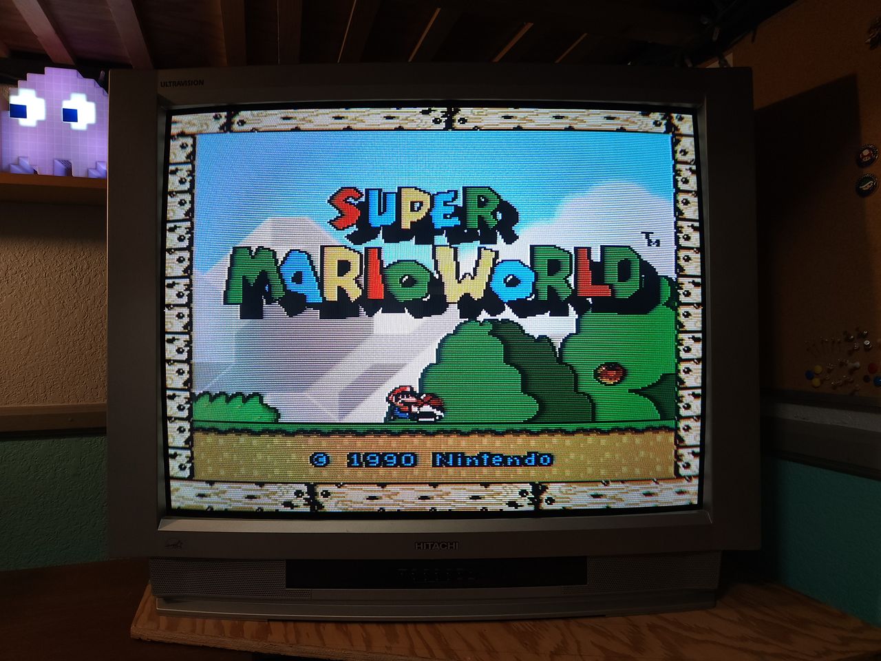
RGB SCART with a 2-Chip SNES as a result of the mux mod.
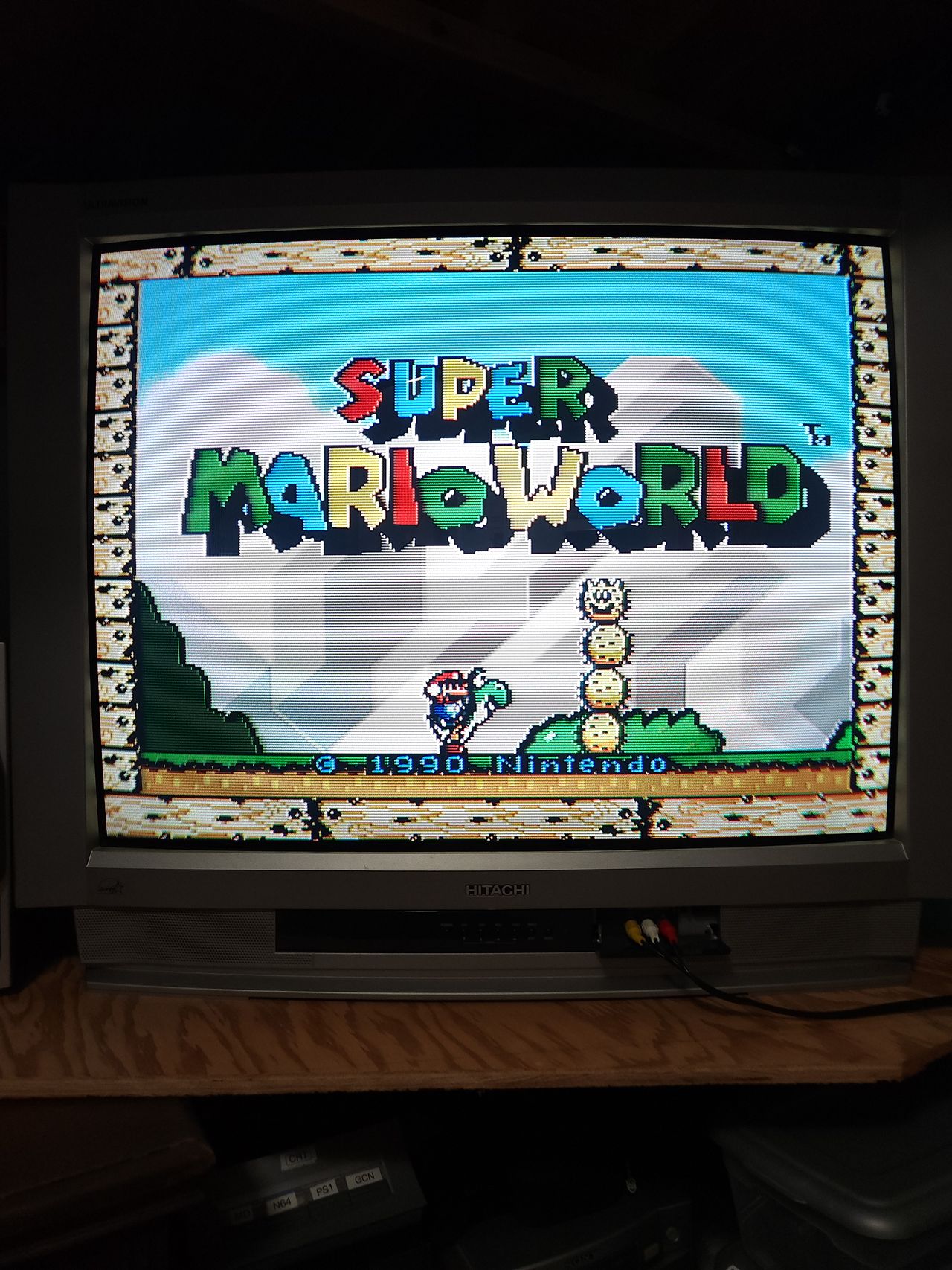
Composite from the same SNES.
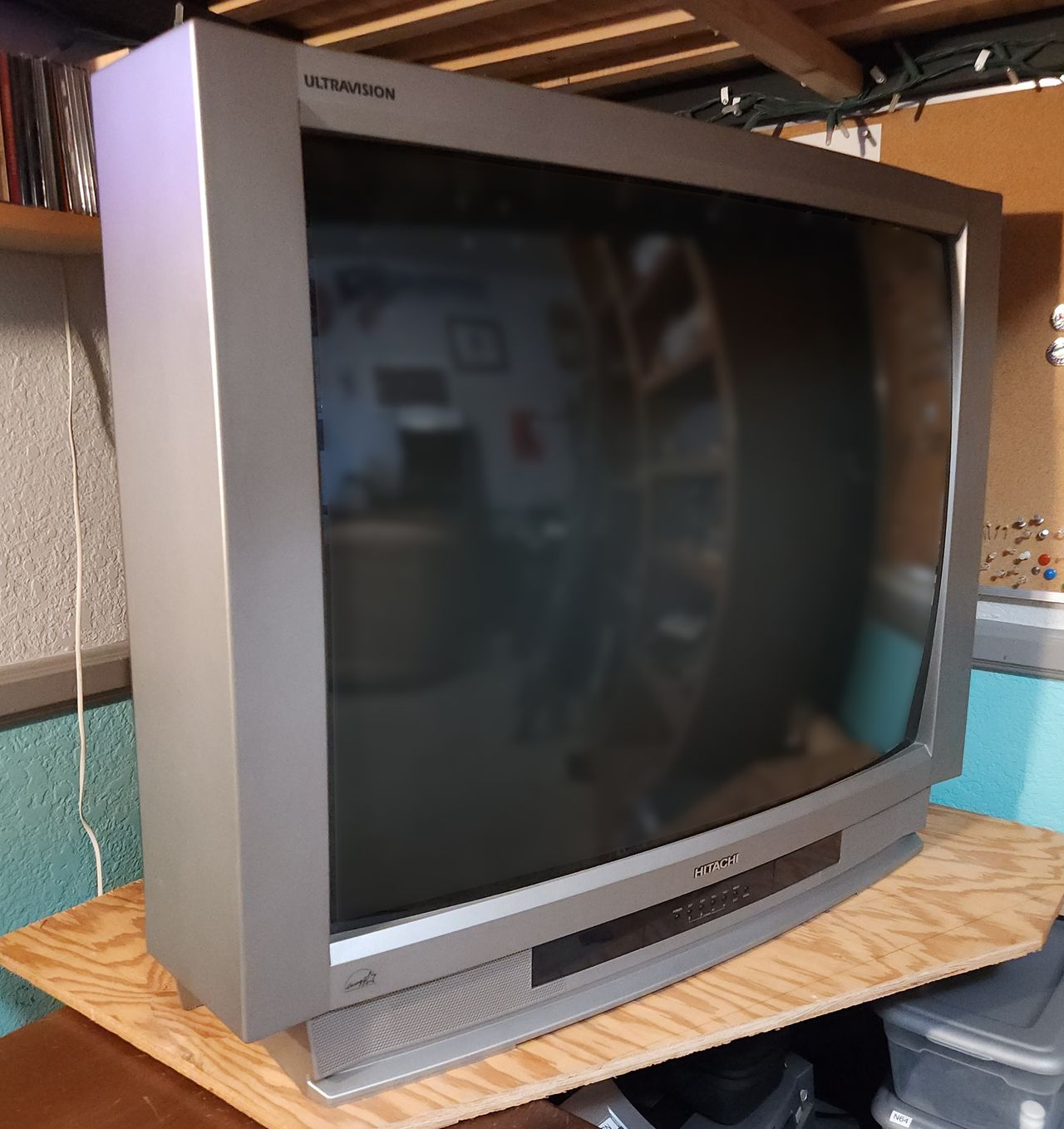
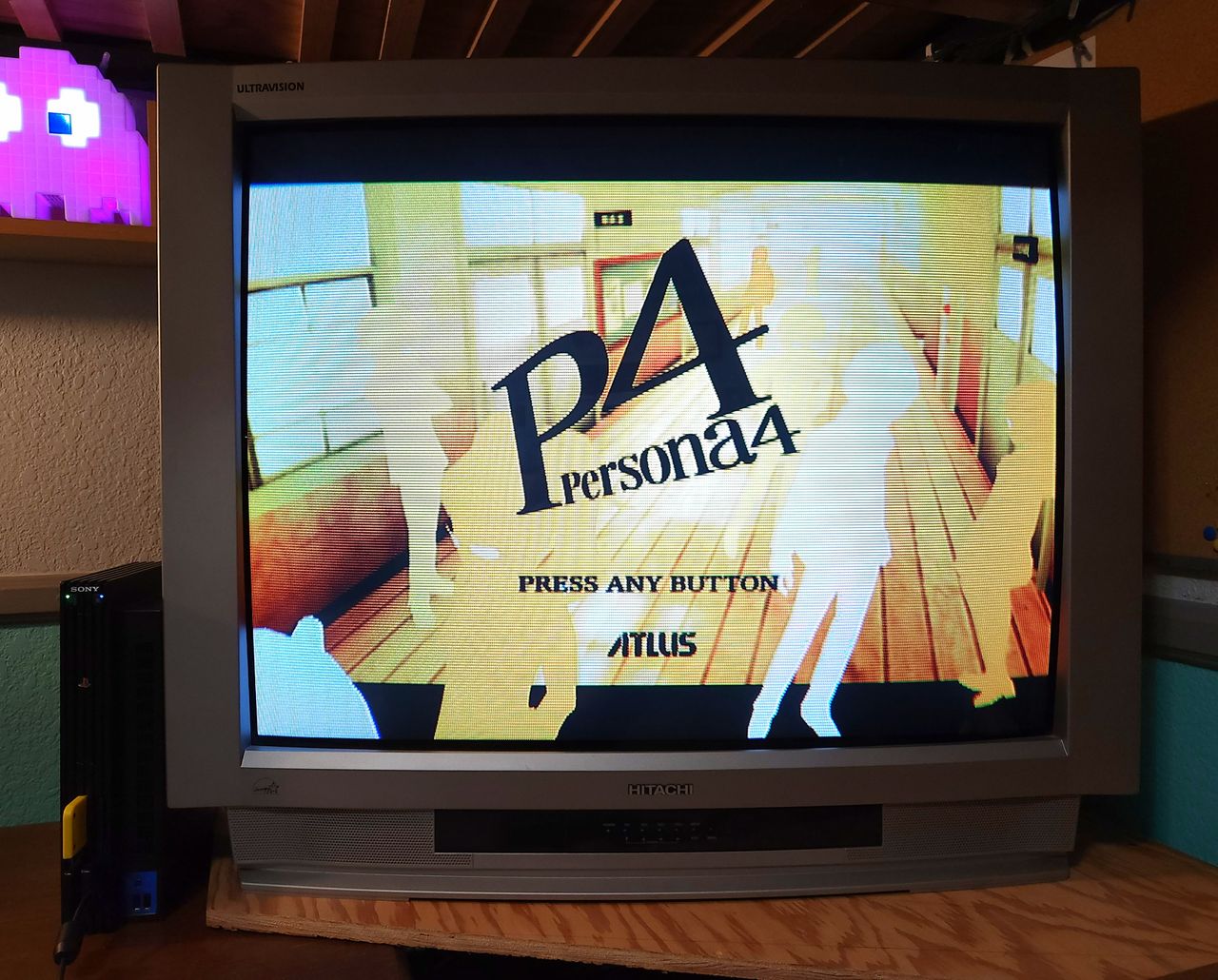
View of the set from the front. It is too heavy for me to lift by myself, so it lives in this corner.
The finished board. R11 (220 Ohm) is mounted on the opposite side. Terminating resistors of 75 ohms worked great for me. I removed the stock 0.1uF caps, so new ones are on this board. The picture is ever so slightly darker, but it isn't noticeable unless you switch inputs back and forth.
I mounted the connector here because it is on the opposite side as the flyback and lies right next to the jungle chip internally.
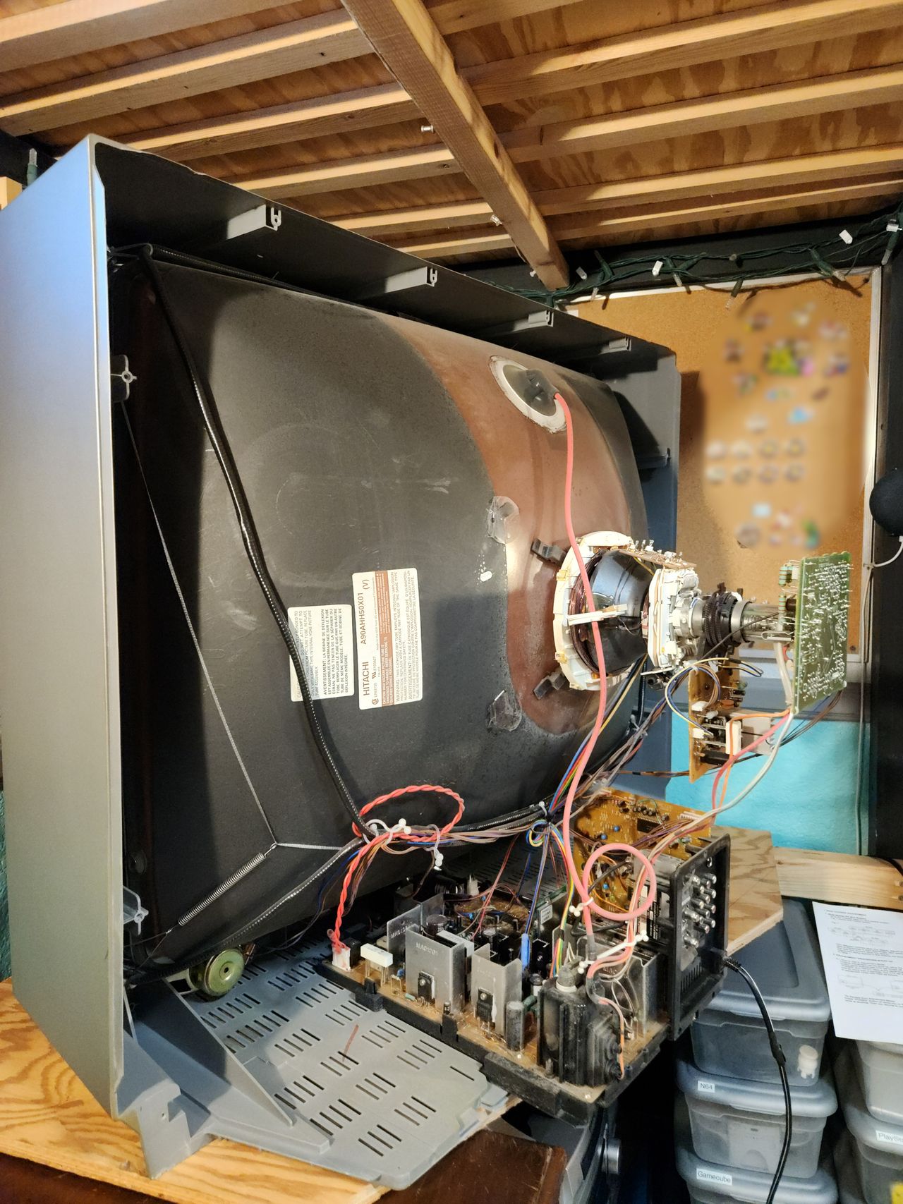
Ample room for modification on the side of the signal board.
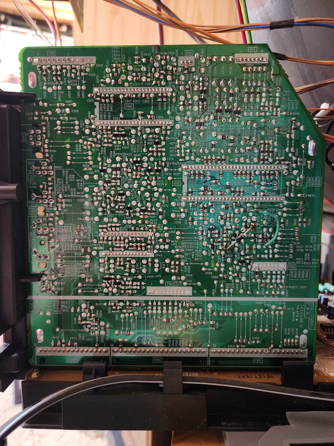
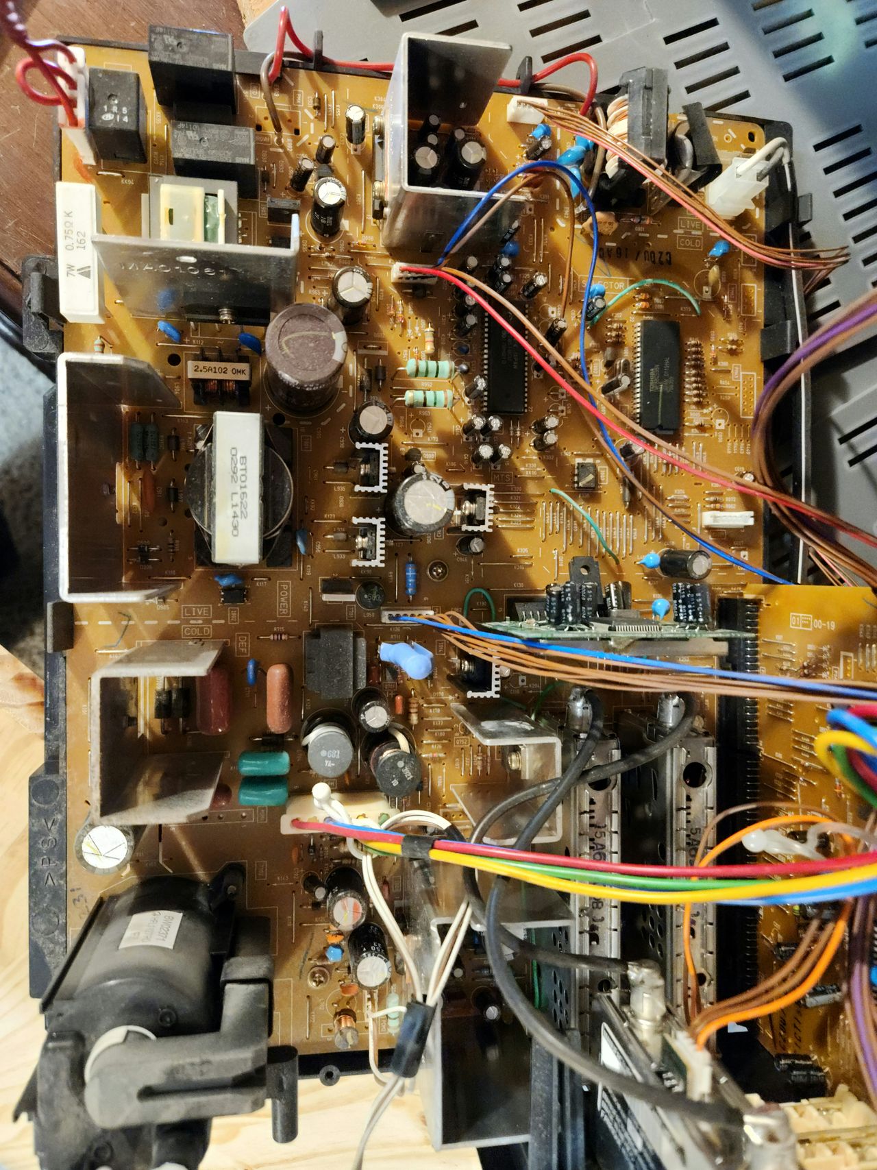
This is the signal board mounted vertically on the chassis. The jungle is labeled I501 near the middle-right of the board.
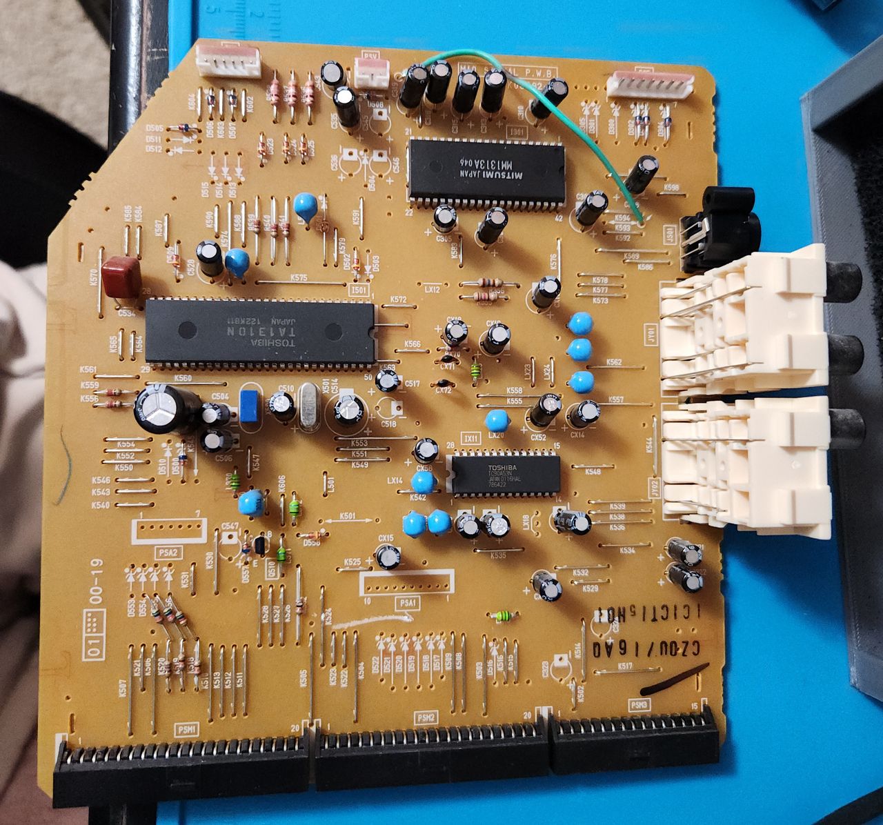
Top side of the signal board. TA1310N is the jungle IC, and MM1313A is the OSD. Note that the PiP chip is not located on this board.
Close up of R521 and C519, C520, and C521. These components need to be removed to inject RGB into the PiP lines.
After de-soldering components, these are the pads I used to inject RGB and blanking. RGB is pins 2-4 respectively. The blanking line connects to pin 5 on the chip, but I found it easier to use R521's pad since it needs to be removed anyway.
On a set without PiP (see 36GX01B), these pins should still be available to solder to since they share the same jungle chip.
Here is the full wiring on the signal board. All wire colors correspond to Sunthar's IDC key for the mux mod. Note that I wired CSYNC to svideo pin 3 because I am using that input instead of composite. This set disables composite sync in favor of svideo when a cable is plugged in. However, if the svideo cable is unplugged, the injected RGB picture will destabilize as CSYNC is effectively disconnected.
If you are planning on using the composite input for some reason, solder CSYNC to that instead. It is labelled pin 10 next to the white audio L and R wires.
In the future, I may add a switch on the back that lets me change between composite sync and svideo sync, but for now it works just fine.
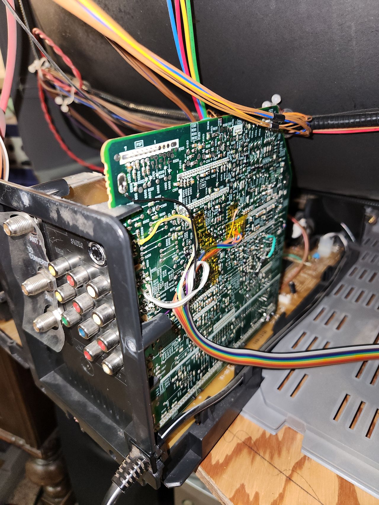
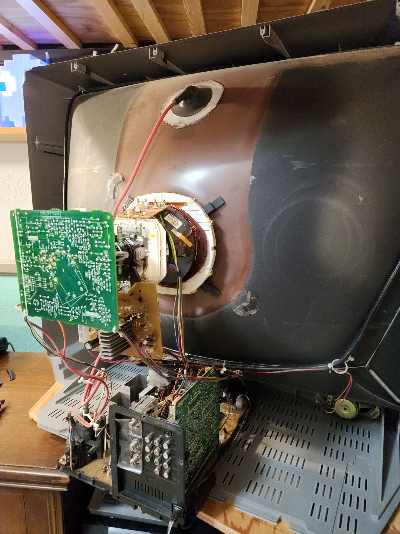
Showcasing just how accessible all the solder points are on this set. You don't even need to remove the chassis if you don't want to.
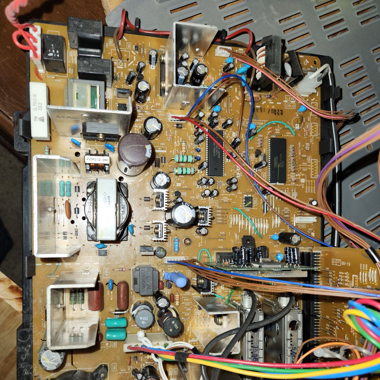
View of the main board. The PiP chip (TMP88CS38N) is near the green wire in the top right of the board. Performing the mod as I did will disable the PiP functionality.
This board sits below the neck and controls VM. Disconnecting the top left wire with 5 brown and 1 blue will disable VM for this set.
Here is where the VM wire connects to the main board if you prefer to disconnect it there. If your set has been on, the resistor with the blue heat shrink over it can be very hot, so please be careful disconnecting the wire.
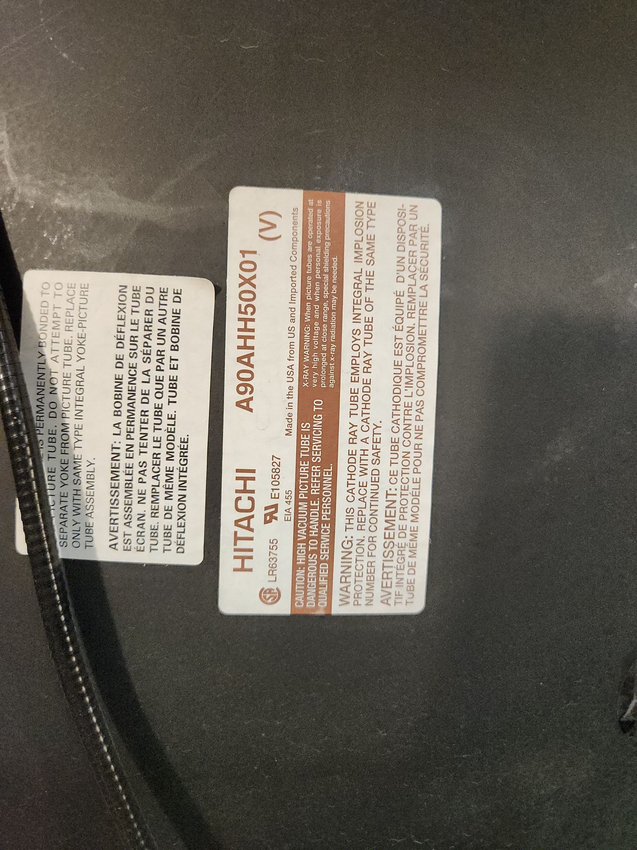
Tube information for those interested.
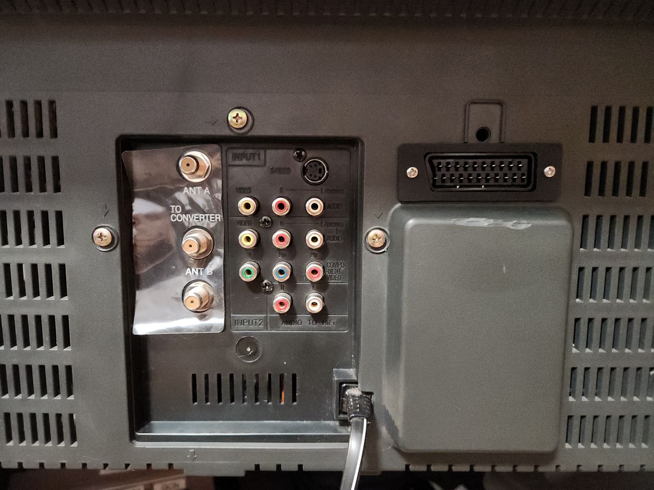
An example of the built in component input. Apologies for the mismatched image, I don't have a cable or console to directly compare with RGB yet. It has a very similar sharpness to the RGB, but the colors appear slightly duller in person.
Reference Photos