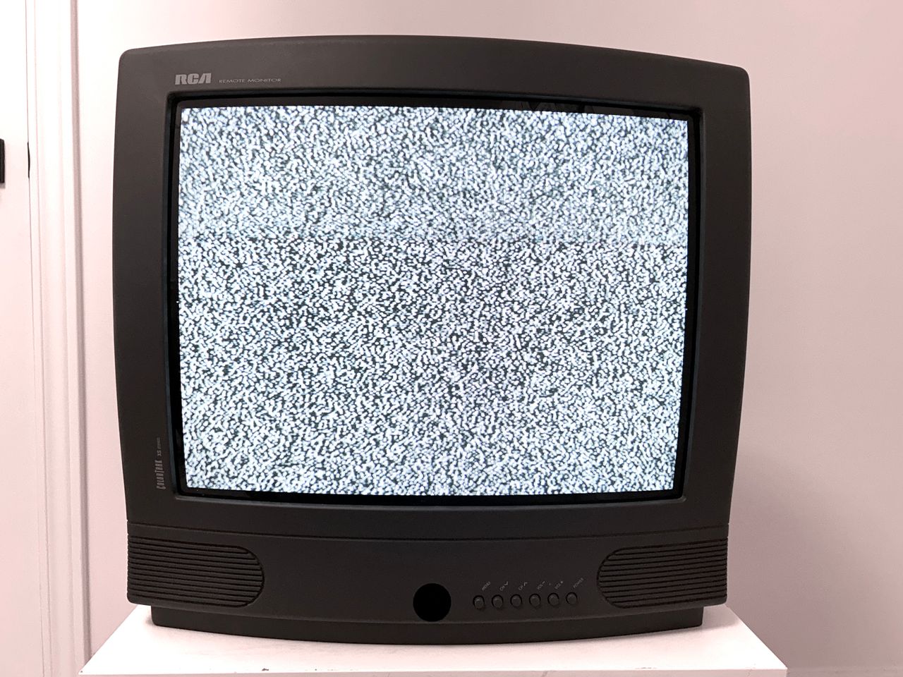
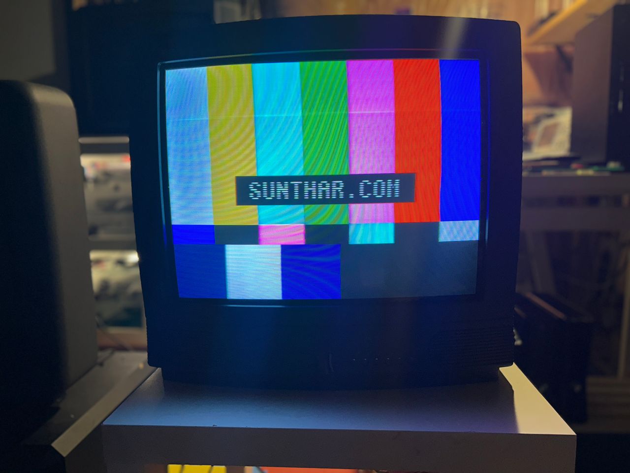
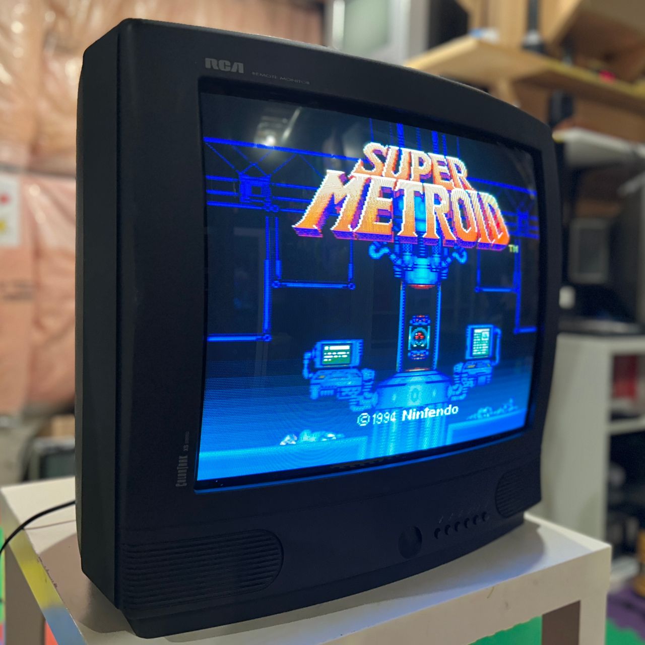
RCA F20352SF
RCA F20352SF CRT RGB mod
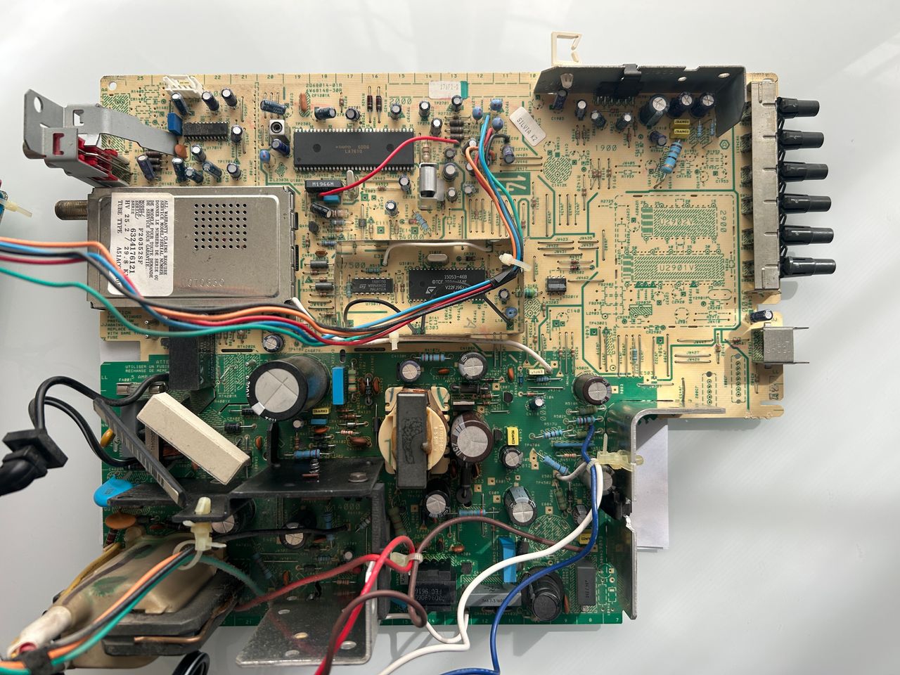
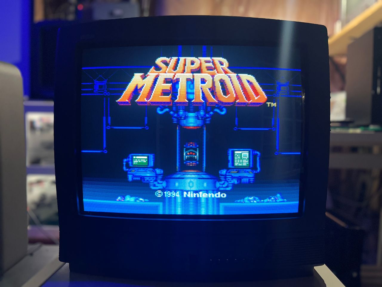
RCA F20352SF, 20" CRT RGB mod. This set is a bit peculiar as it has transistor that amplifies the RGB signal from OSD.
View full CRT details and more mod examples →
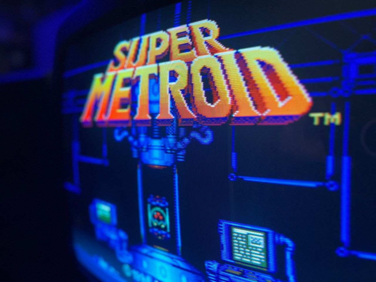
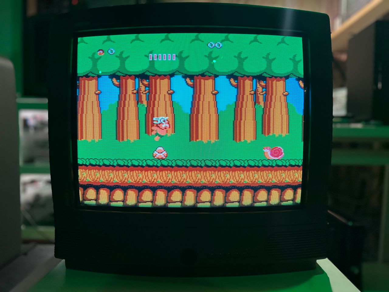
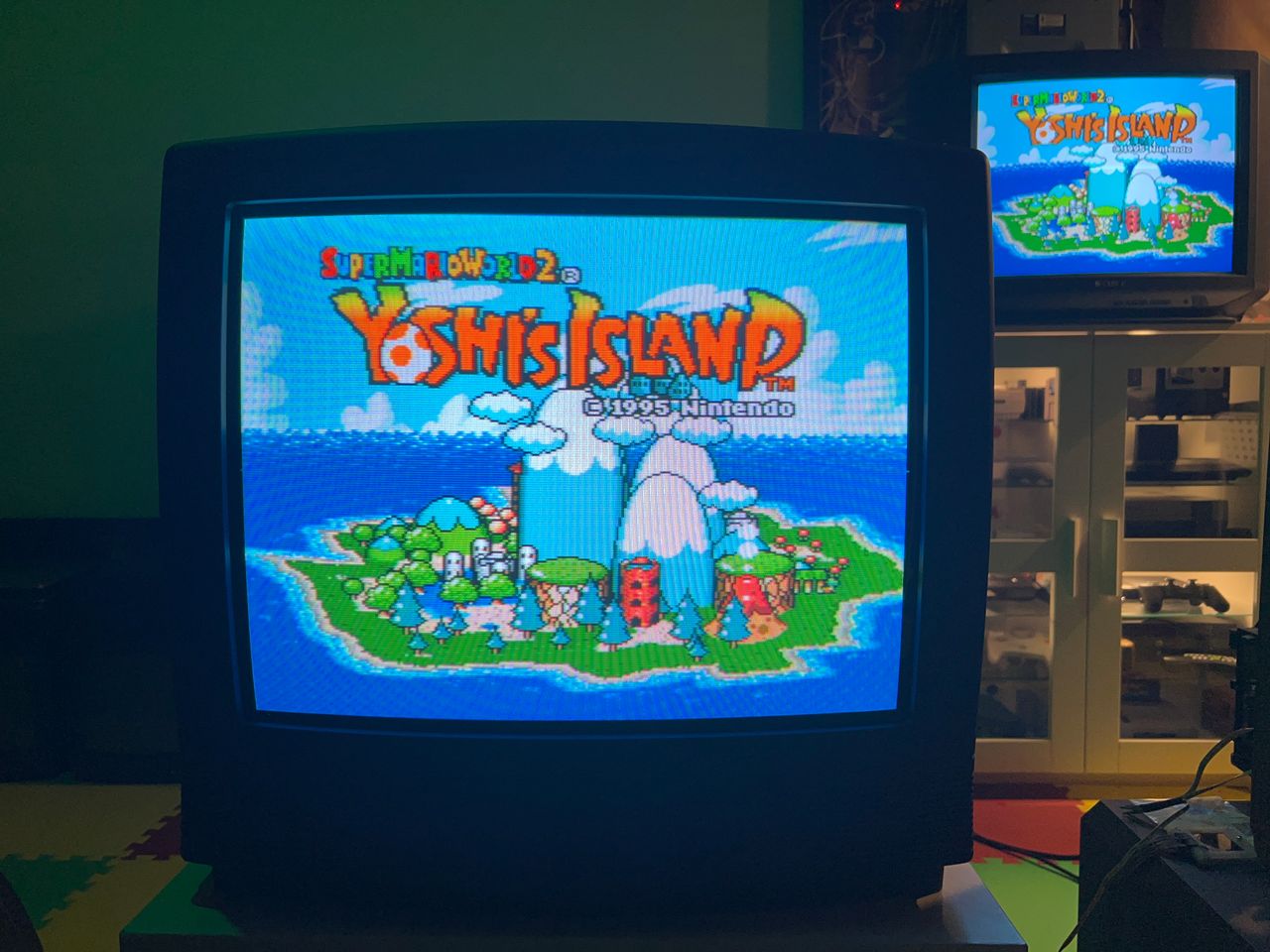
This turned out beautifully. This 20" set features an RCA tube that delivers a soft, arcade-like glow. The same mod should work for models using the CTC177 chassis or LA610 chroma ICs. Several mods shared on Shmups appear to have failed due to the unusual transistor amp present in the RGB path. Several also skipped the required diodes on the R, G, B, and blanking lines — these are essential for reducing noise. The models listed below can benefit from this tutorial, though minor variations may apply.
- RCA 27CR620
- Chassis CTC177AH
Contributors
Thank you to everyone who contributed to this guide:
- Sunthar — photos and documentation
CRT safety
Caution
You can die doing this! So read carefully! CRT TV is not a toy. Do not open a CRT TV. If you don't have any prior knowledge about handling high voltage devices, this guide is not for you. CRT TV contains high enough voltage (20,000+ V) and current to be deadly, even when it is turned off.
Plan of attack
Manuals and Datasheets
Specs
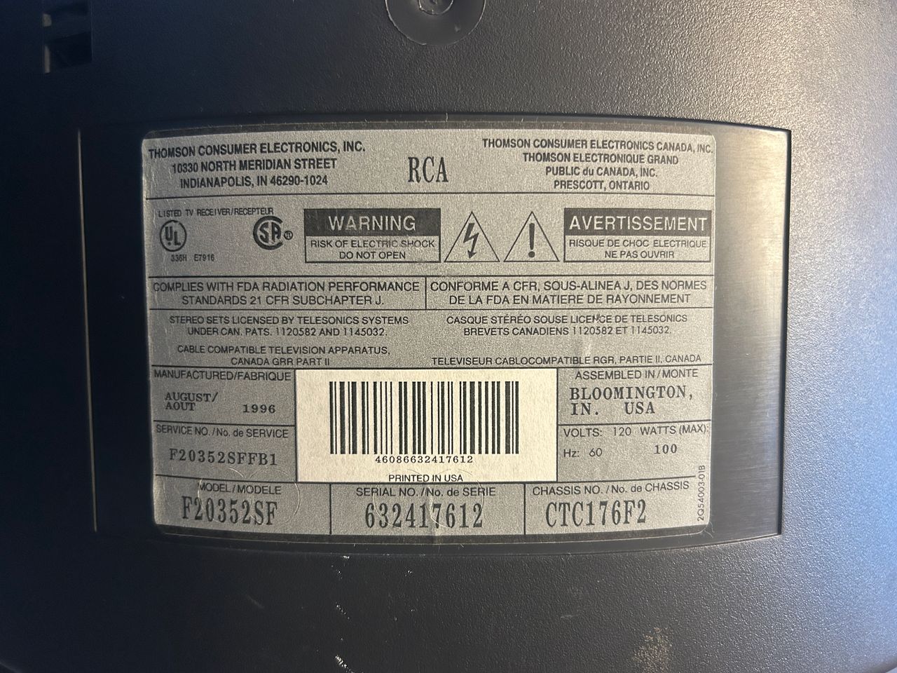
- Year:
- Chassis: CTC176F2, CTC176
- Tube: RCA A51ACG34X02
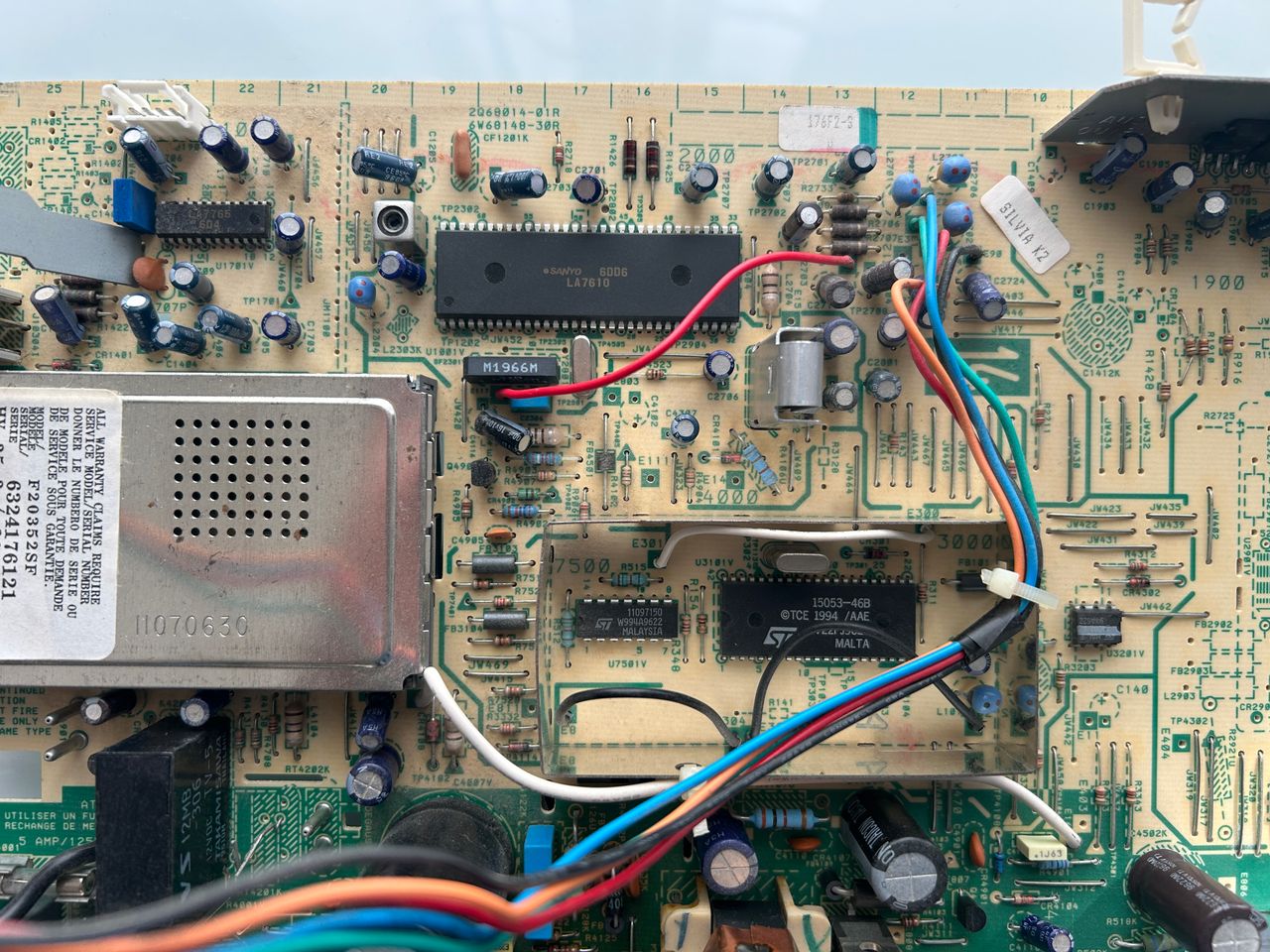
- Jungle Chip: Sanyo LA7610
- OSD Chip: ST15053-46B
- Screen Size: 20"
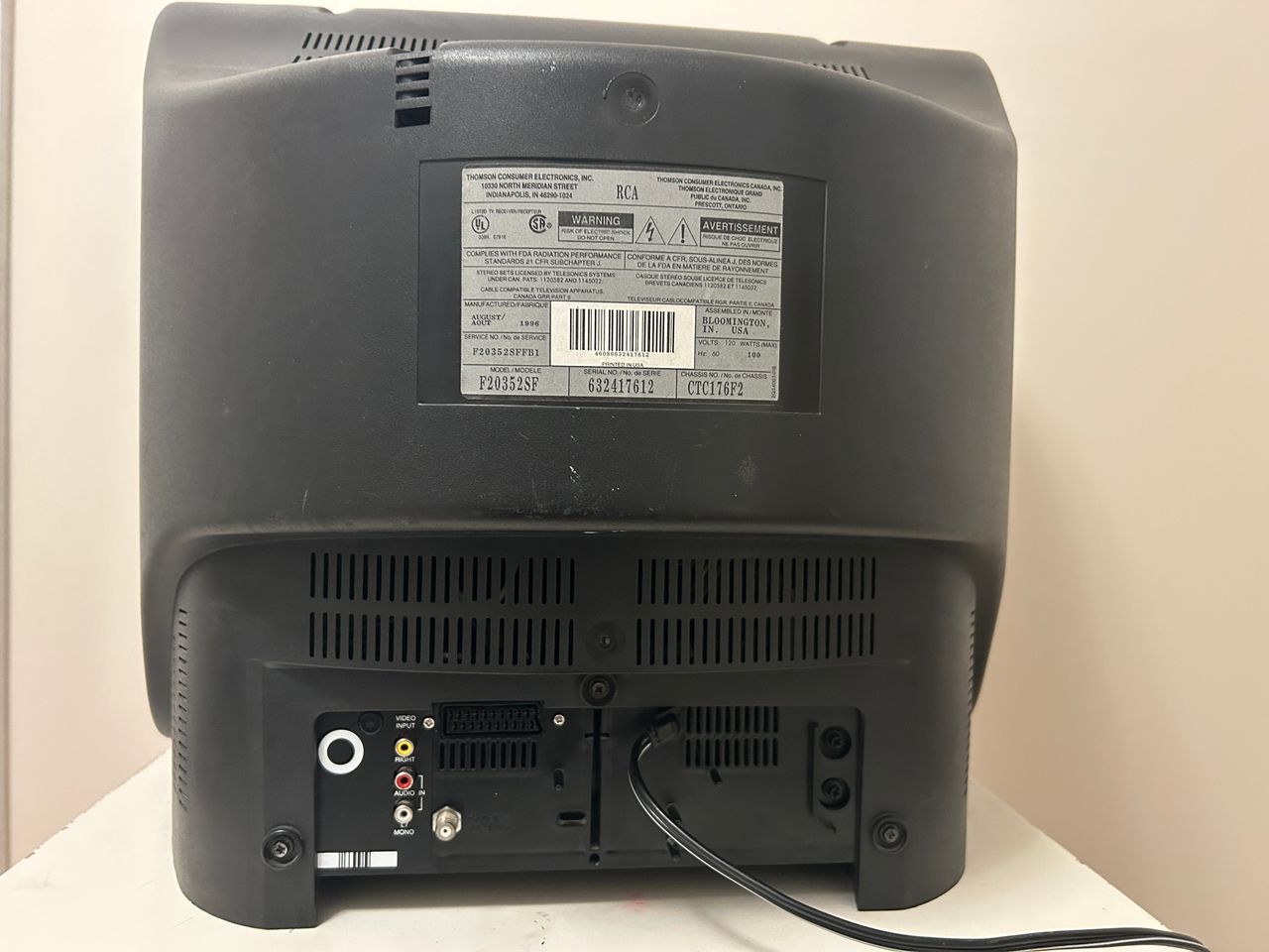
- Inputs: Composite, RF
RGB mux diagram
Prepare the mux diagram. If you are building your own circuit, this diagram should help.
Performing the mod
STEP 1: Remove the following components
Remove the following RGB resistors that are connected to the ground.
- R317 (120Ω)
- R319 (120Ω)
- R321 (120Ω)
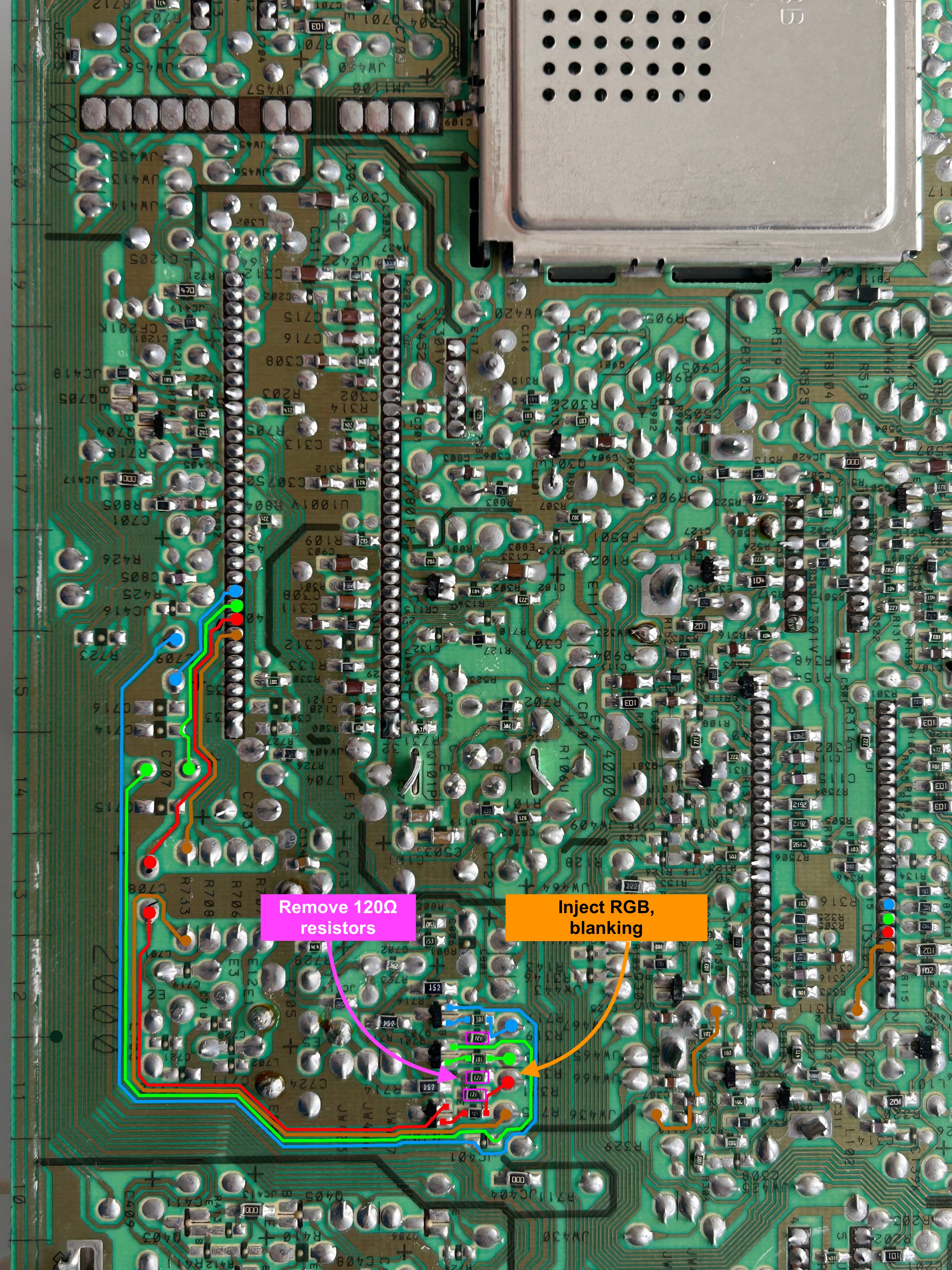
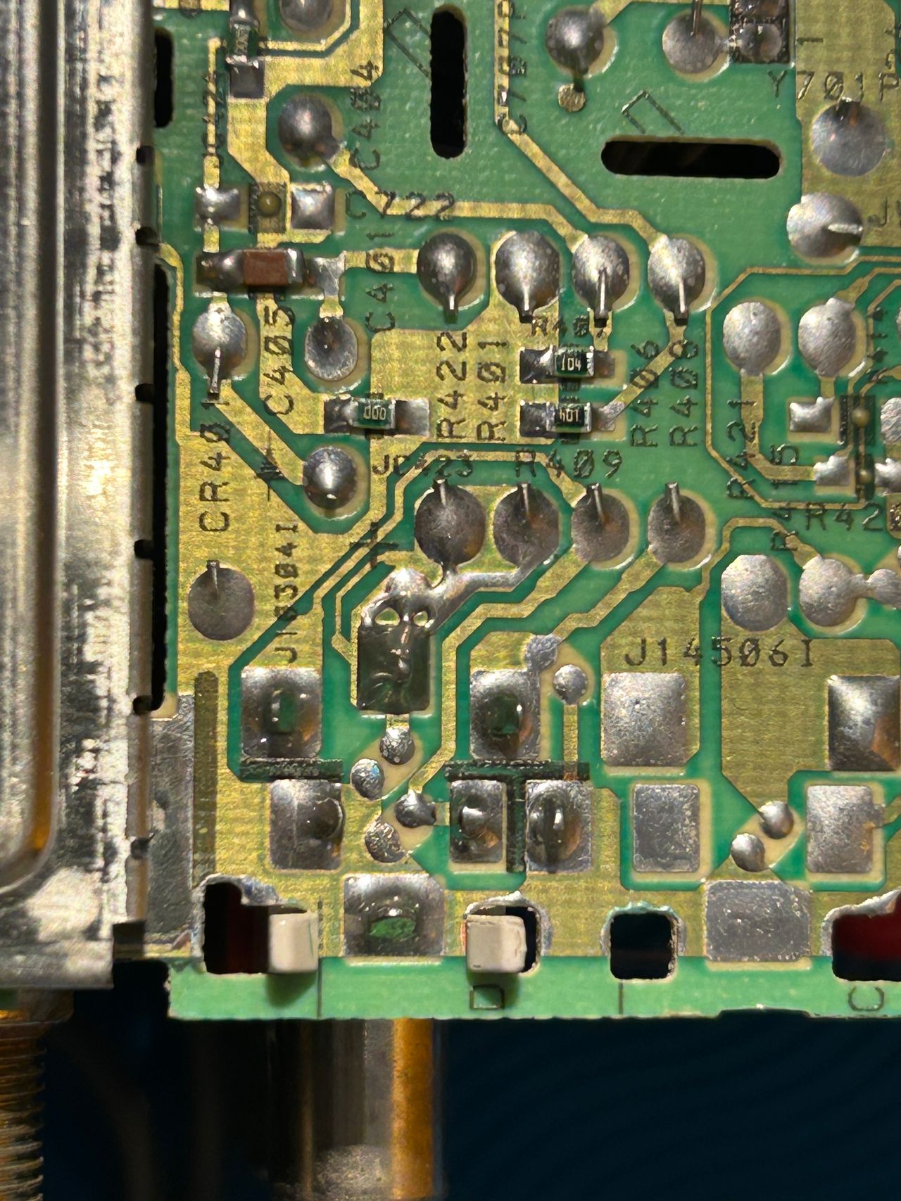
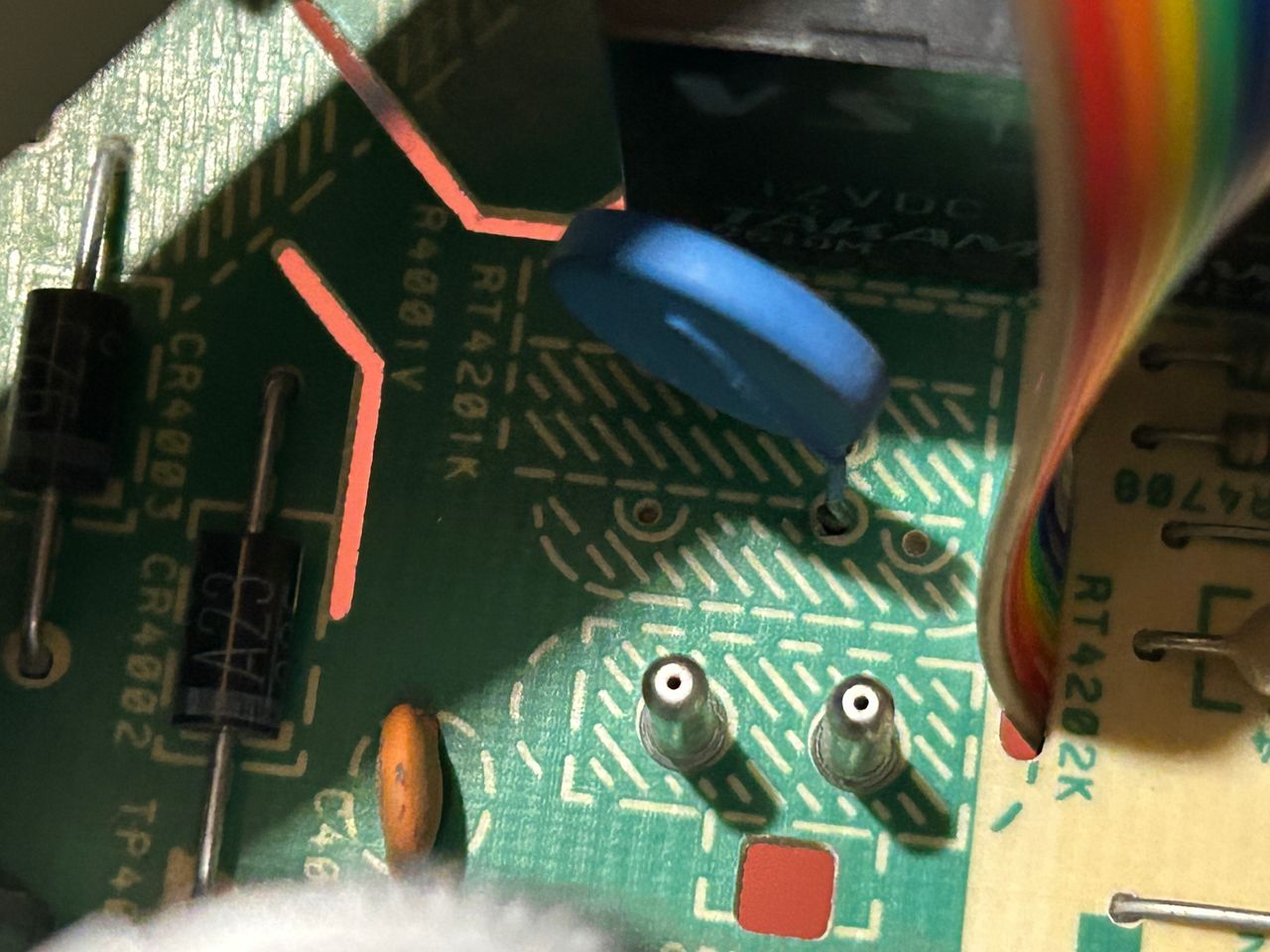
STEP 2: Add inline diodes to reduce interference
This is an important step to replace the following jumpers with diodes.
- JW466
- JW465
- JW467
- JW436
Not doing this means, there will be interferene. Pay attention to the direction of the diode, which is represented by the black bar on the diode.

STEP 3: Connect RGB and Blanking
Attach RGB wires and blanking on exactly where these resistors were removed.

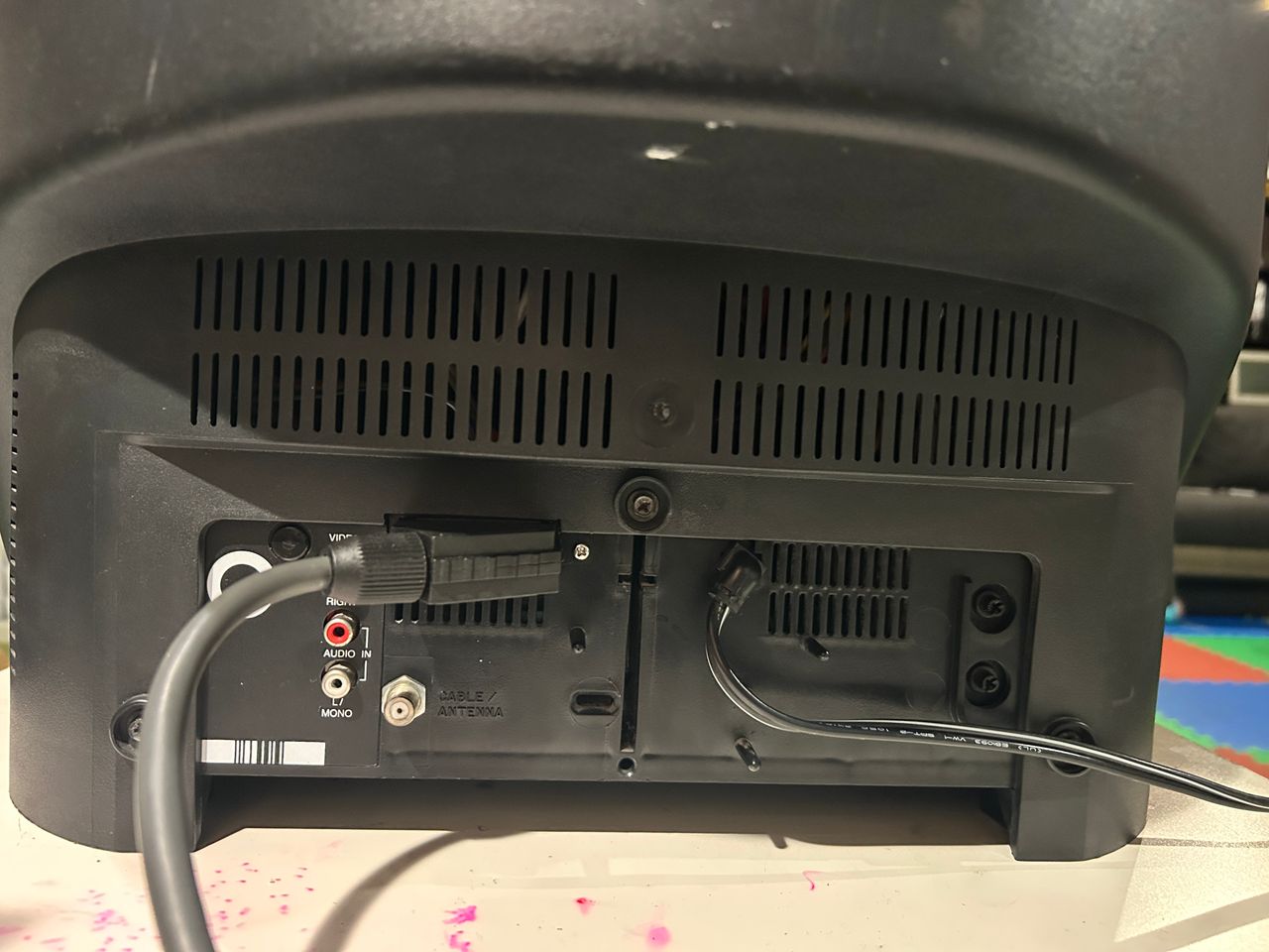
STEP 4: Permanently enable stereo (optional)
Stereo can be permanently enabled by removing the lip seen in the below picture. Alternatively, plugging anything into the red RCA port will also activate stereo.

STEP 5: Connect Audio, Sync and Ground
Composite Sync, Audio and Ground wires should be connected.

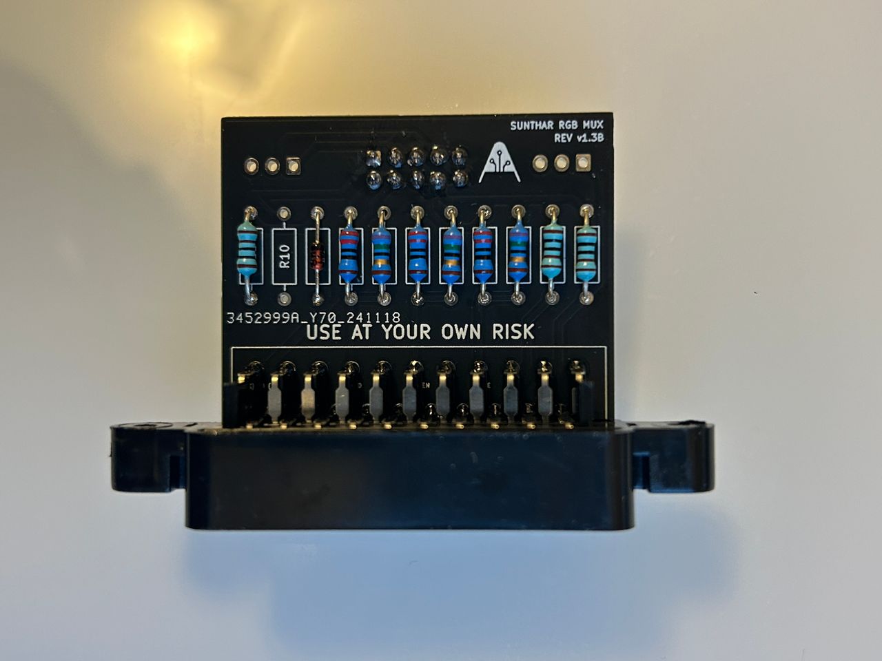
STEP 6: Build your mux board/circuit
This mod uses the RGB mux board. This is optional, but will make your mod easier and stable. You can also create the circuit presented in the schematics above without the board. Please also checkout the mux calculator to play with your own values.
| Component | Value |
|---|---|
| RGB/OSD inline resistor (chassis) | 1kΩ |
| Removed RGB/OSD resistor (chassis) | 120Ω |
| RGB inline diode method (chassis) | Yes |
| RGB termination (R1, R2, R3) | 75Ω |
| RGB inline (R4, R5, R6) | 120Ω |
| Audio LR (R7, R8) | 1kΩ |
| Diode (R9) | 1N4148 |
| Blanking Ground Resistor (R10) | open |
| Blanking Resistor (R11) | 1kΩ |
Compatible mux boards:
Pictures
Photos by Sunthar's Super Store


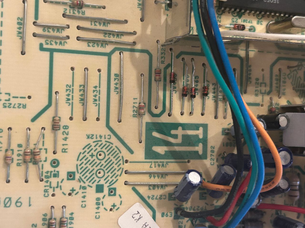
Diodes are important to reduce interference.
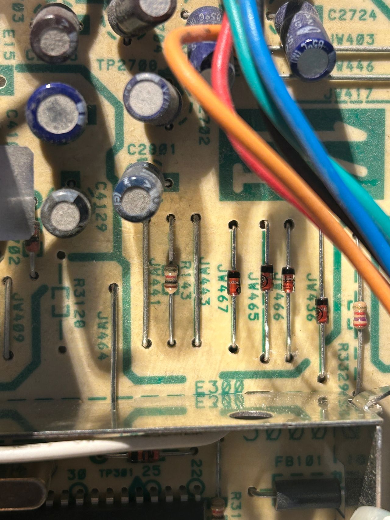
Jumpers for R, G, B and blanking replaced with diodes.
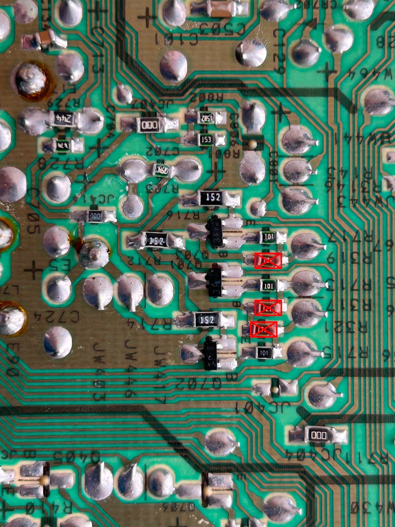
Remove these three 120ohm resistors
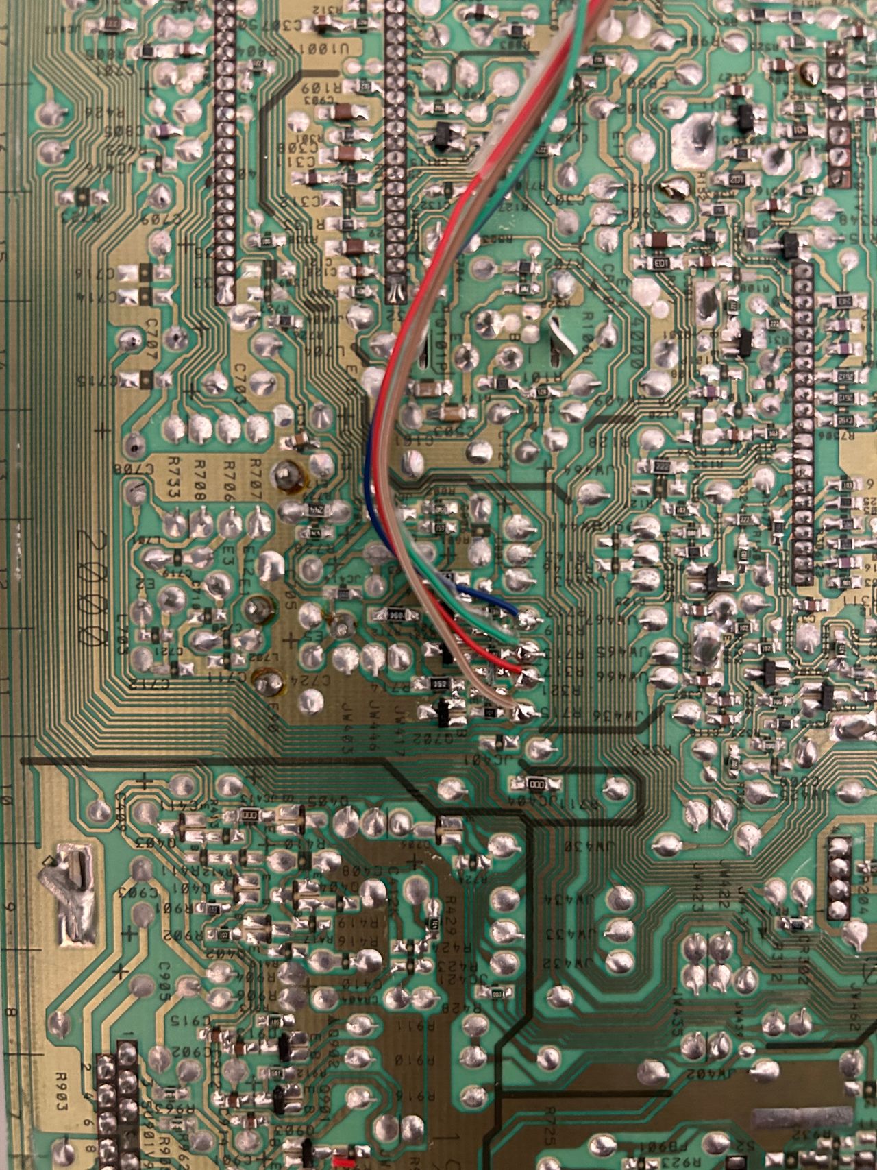
R, G, B, blanking wires soldered
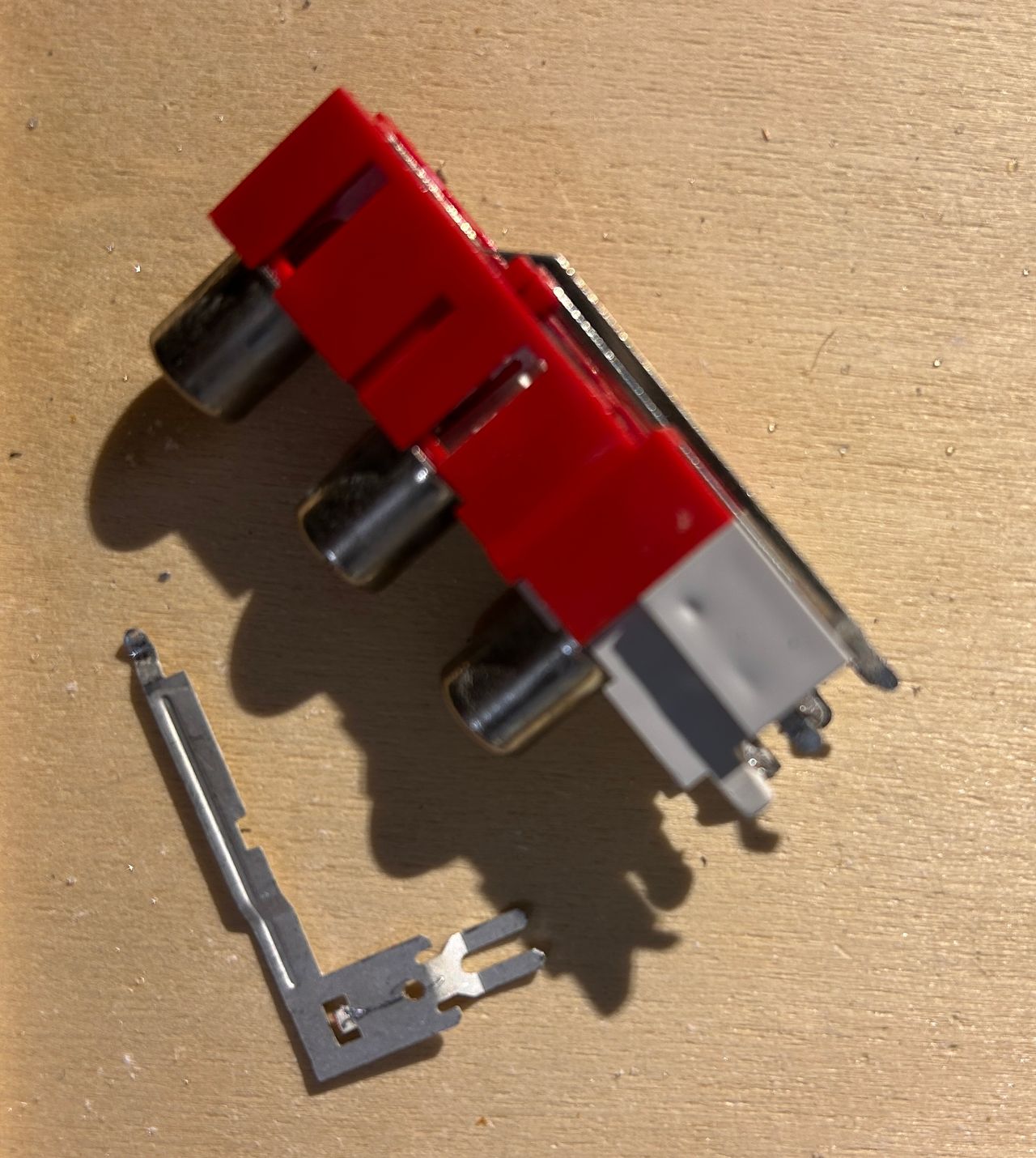
Stereo can be permanently enabled by removing the lip.
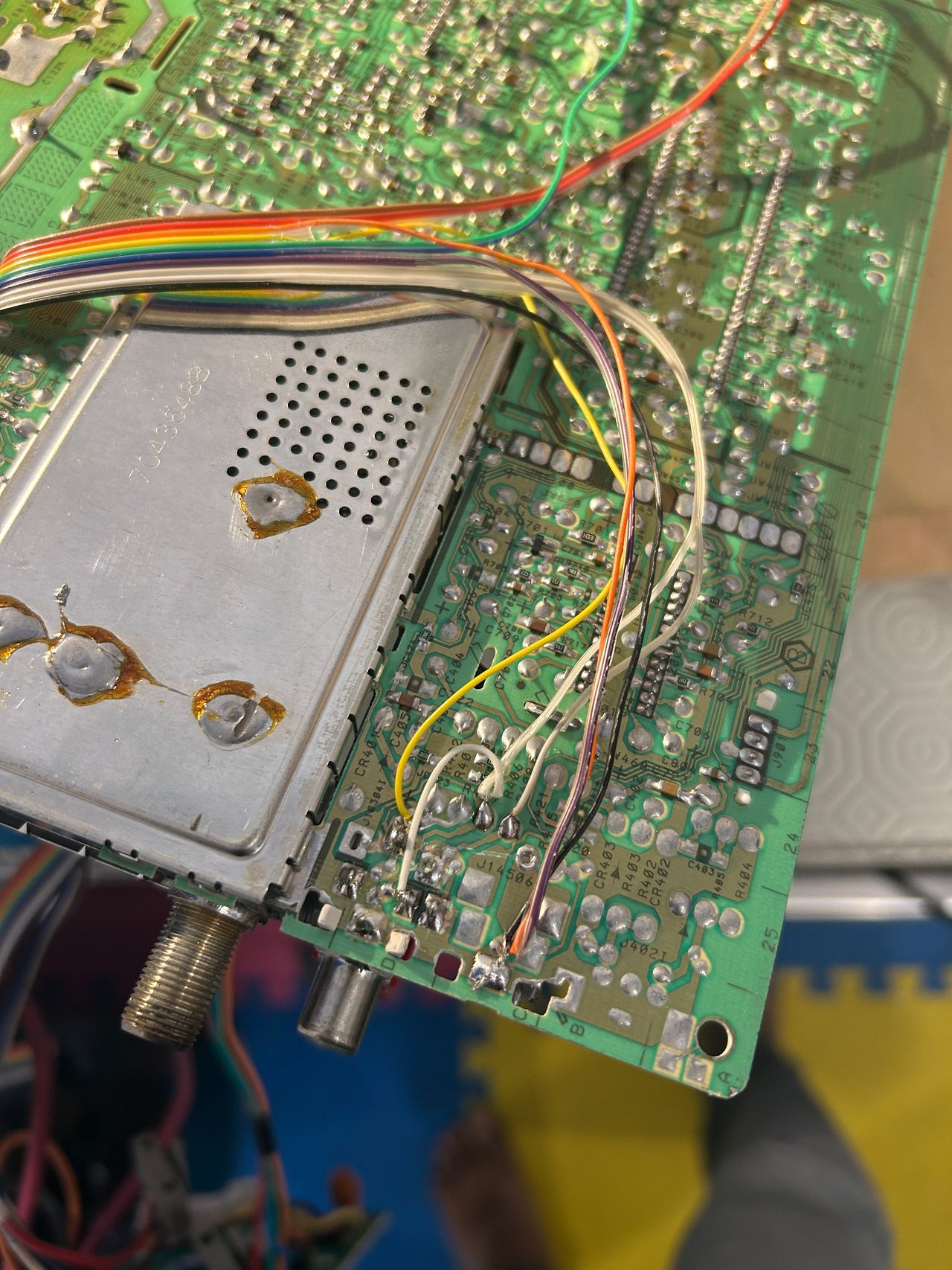
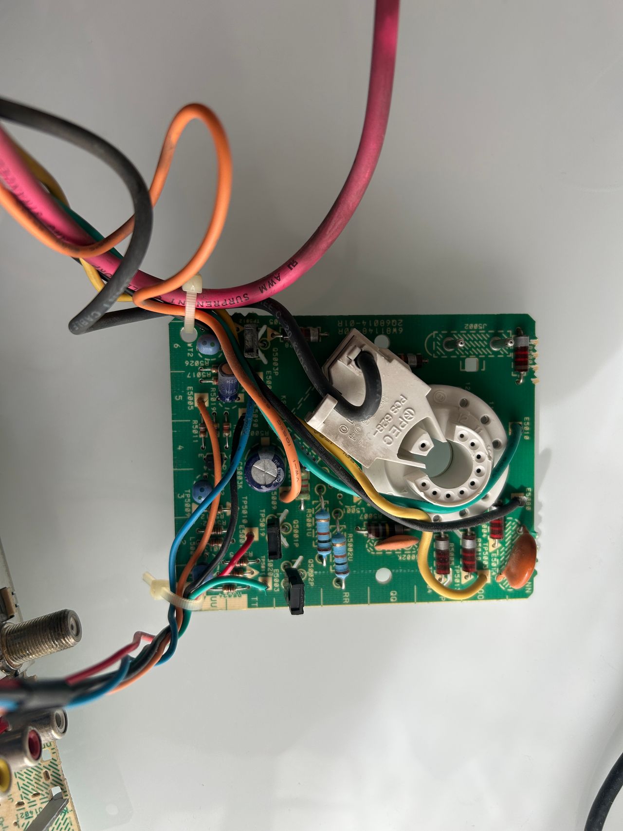
Sync, Audio and Ground wires soldered
Traces below the composite input prior to soldering sync, ground
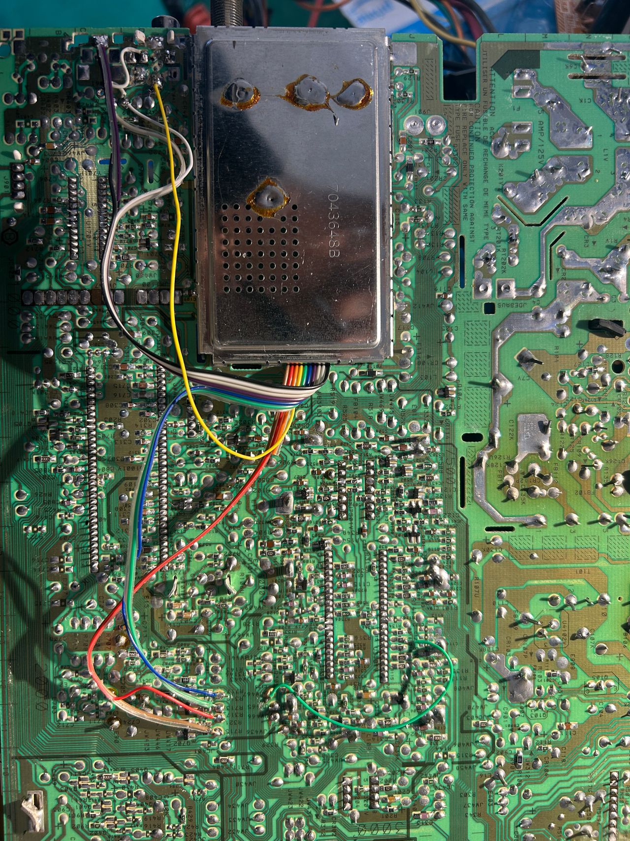
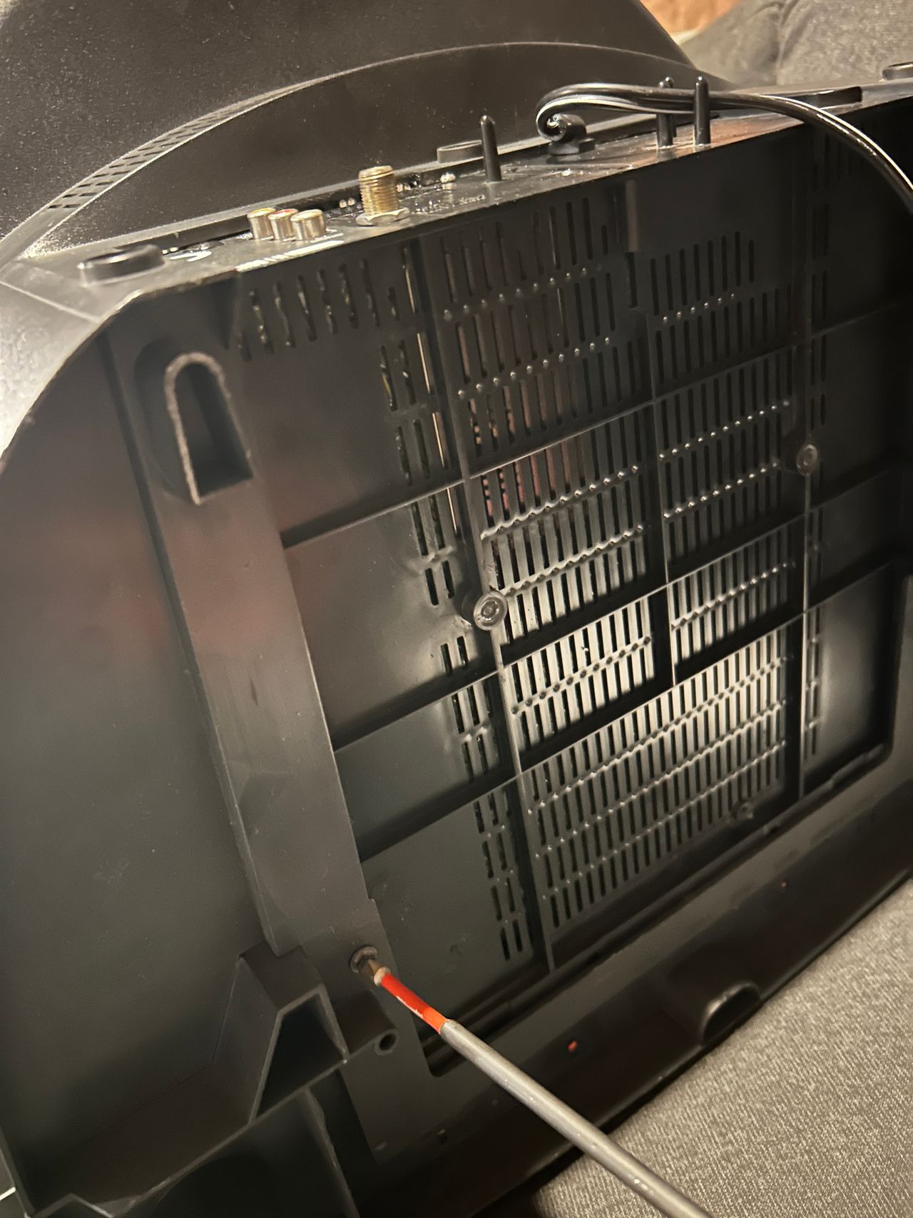
Rainbow wires can be routed through the little opening on the chassis.
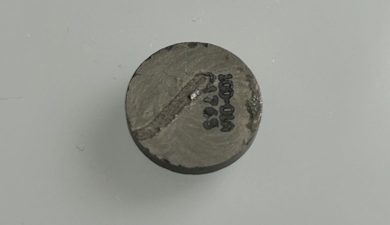
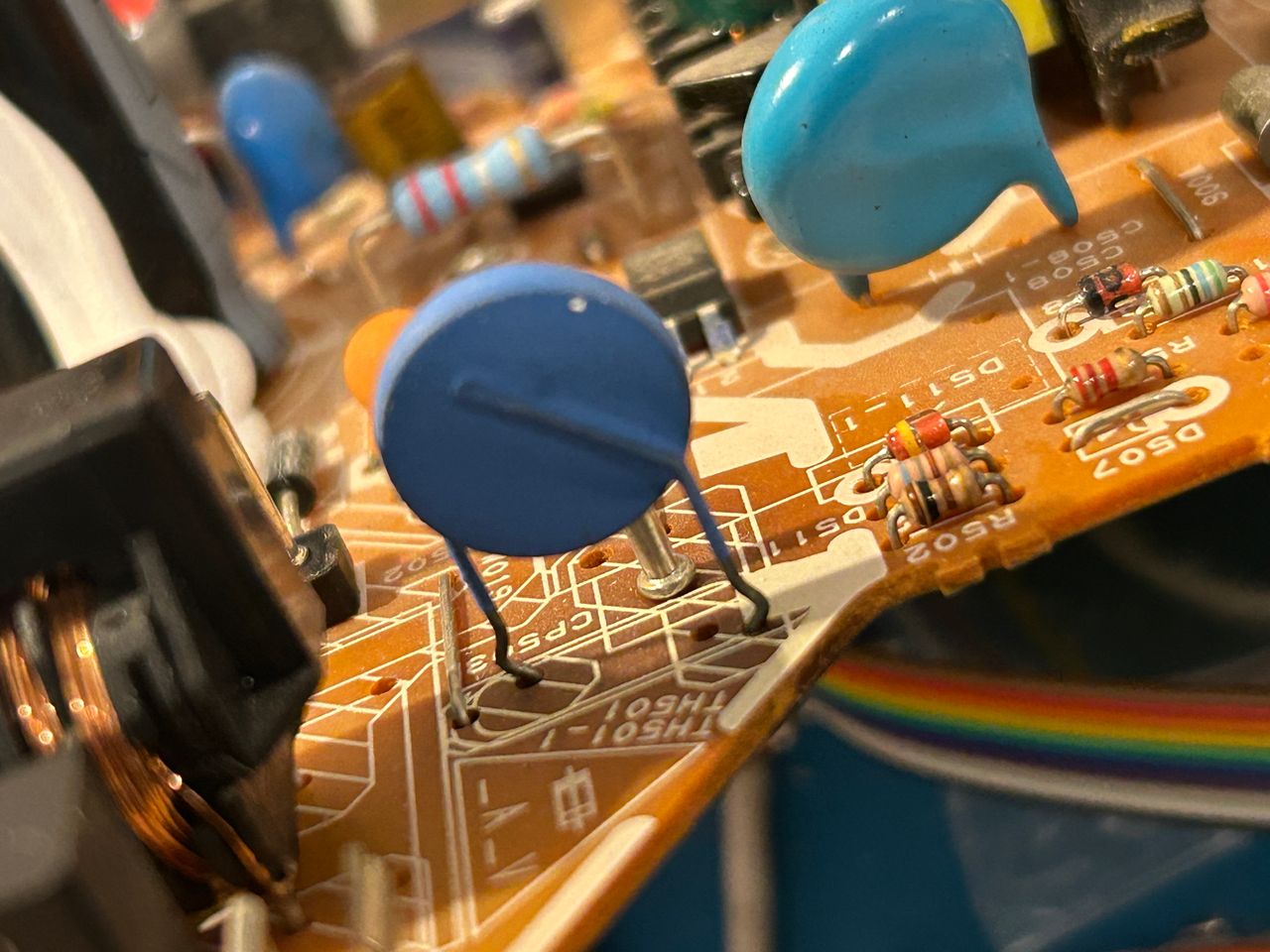
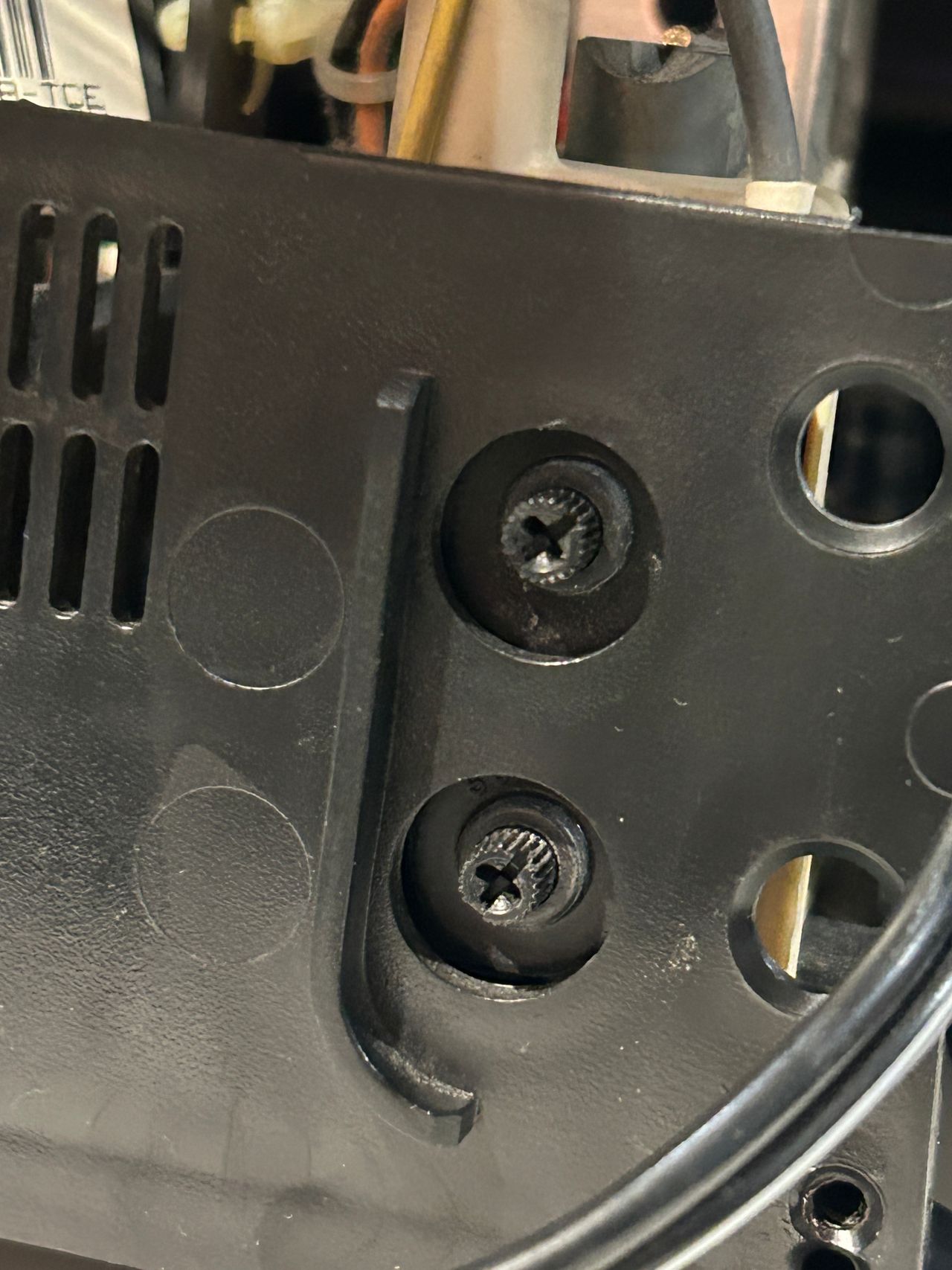
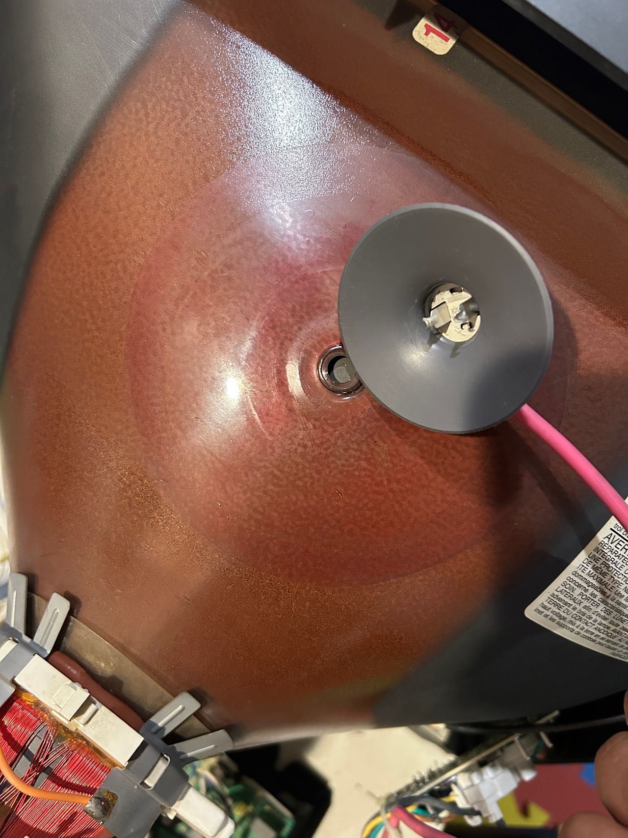
This is a common problem on this set where the thermistor breaks off.
Equivalent thermistor was taken from Toshiba 13A24
Thermistor transplanted
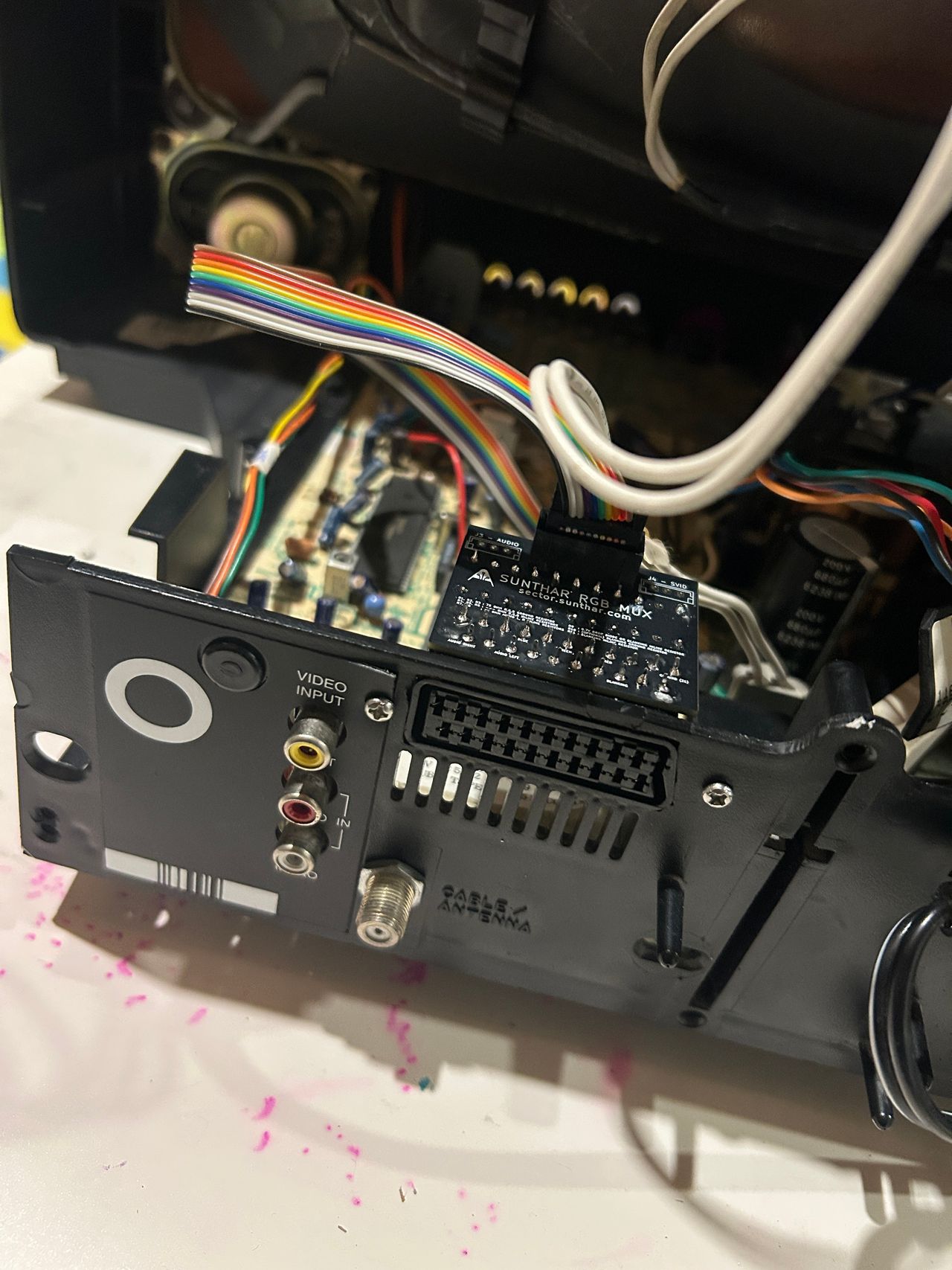
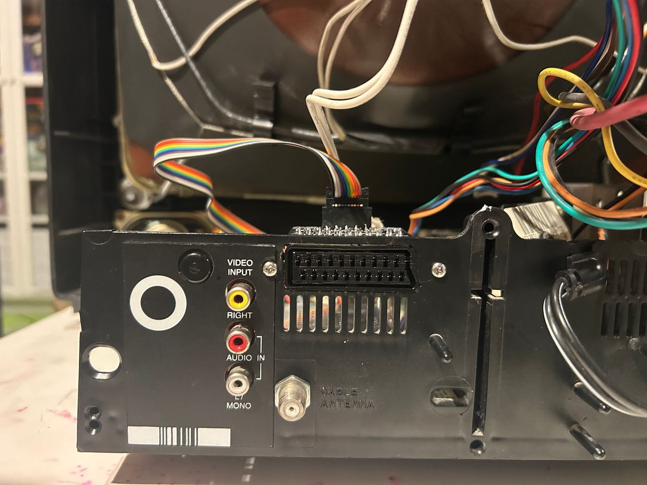
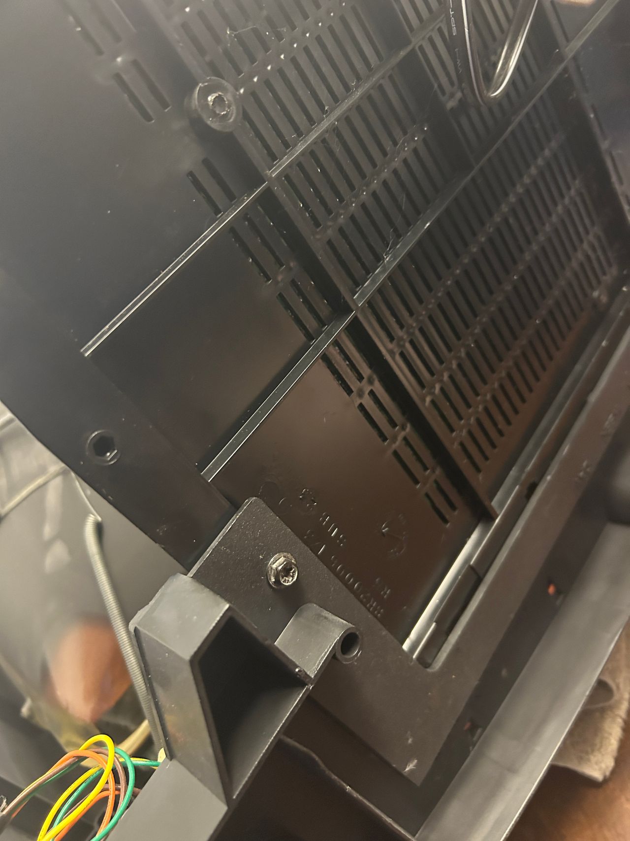
In hindsight, this wasn’t the ideal location for mounting the SCART connector. I also had to trim the rear cover to make it fit. A better approach would be to mount the SCART connector directly on the rear cover or relocate it to the grille just below.
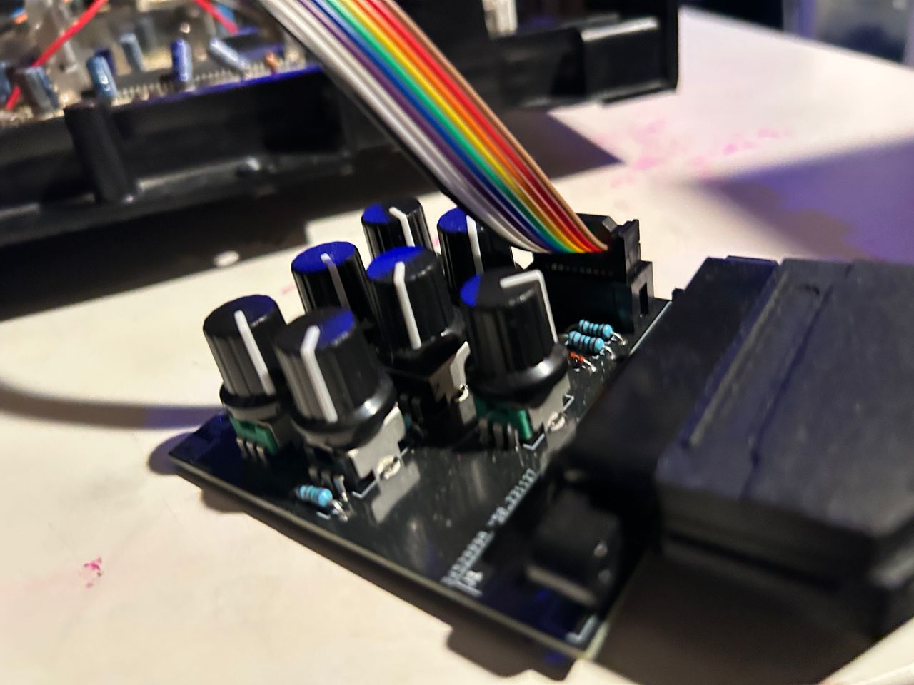
RGB tuner in use to fine tune the colors.
Reference Photos