
Sony KV (BA-1)

SuntharAbout 3 minCRT RGB modKV-13TR28KV-13TR29KV-13V50KV-20TR23KV-20TS29KV-20TS32KV-20TS50KV-20V50

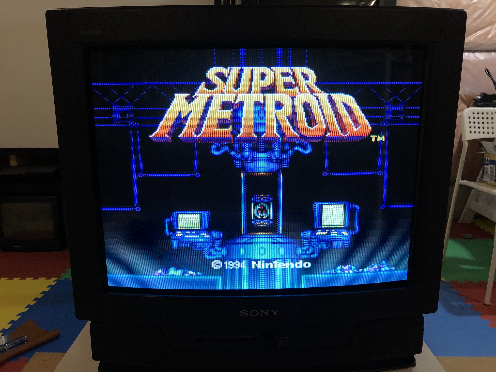
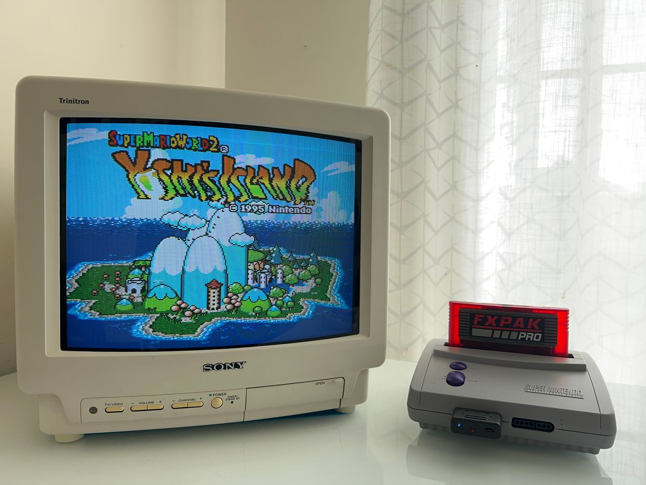
Sony BA-1 chassis CRT RGB mod

Bring your Sony CRT to life with vibrant RGB colors! Below mod was performed on KV-20TS29.

img

This tutorial should also cover the RGB mod for the below models with the BA-1 chassis. However, there might be slight differences.

13" models

  • KV-13TR28
  • KV-13TR29
  • KV-13V50

20" models

  • KV-20TR23
  • KV-20TS29
  • KV-20TS32
  • KV-20TS50
  • KV-20V50

Inspired by the following mods

CRT safety

Caution

You can die doing this! So read carefully! CRT TV is not a toy. Do not open a CRT TV. If you don't have any prior knowledge about handling high voltage devices, this guide is not for you. CRT TV contains high enough voltage (20,000+ V) and current to be deadly, even when it is turned off.

READ THIS BEFORE CONTINUING

Plan of attack

READ THIS TO PREPARE

Theory

Sometimes it is nice to know the theory behind the mod. I have put this on a separate page. This shows how the various resistor values are calculated.

READ THE RGB MODDING THEORY

Service manuals

Specs

Sony KV-20TS29

  • Manufactured: October 2001, Mexico
  • NTSC, 60 Hz
  • Chassis: BA-1
  • Tube: A51JUH51X
  • Jungle Chip: CXA1465AS

Sony KV-13TR28

  • Manufactured: April 1994, Mexico
  • NTSC, 60 Hz
  • Chassis: BA-1
  • Tube: A34JBU70X
  • Jungle Chip: CXA1465AS

Schematics

Sony BA-1 schematics

Red is shown for reference. Blanking (Ys), Red, Green, Blue lines are exposed on 5, 6, 7, 8 of the CN101 connector.

Performing the mod

You can't ask for a more straightforward RGB mod.

Fortunately this chassis doesn't require any muxing. You can pass R, G, B through a 0.1uF, 75ohm terminated wire directly to the CN101 header. Blanking (Ys) can be fed through a 1kΩ + 0.7V didoe to pin 5 of the CN101 header.

STEP 1: Connect RGB, Blanking and Audio

You only need about a maxium 1 feet length of ribbon cable. Shorter this cable the better as it reduces interferece.

See picture to see where blanking, R, G, B should be connected. Blanking (Ys), Red, Green, Blue lines are exposed on 5, 6, 7, 8 of the CN101 connector.

img

V1 V-IN for SYNC V1 L-IN for Left Audio V1 R-IN for Right Audio E for GROUND

img

STEP 2: Build your mux board (optional)

Below mod uses the RGB mux board. However, it is optional for BA-1 chassis. Using the mux board makes the mod neater and easier. Please note for this mod, 0.1uF caps were used in place of R4, R5, R6 resistors.

Buy your RGB mux board with the necessary parts to complete this mod

TV ModelKV-20TS29KV-13TR28
Audio LR (R7, R8)1kΩ1kΩ
RGB termination (R1, R2, R3)75Ω75Ω
RGB inline caps (R4, R5, R6)0.1uF0.1uF
Diode (R9)1N41481N4148
Blanking Resistor (R11)1kΩ1kΩ

Caps were used instead of resistors.

img

Buy your RGB mux board with the necessary parts to complete this mod

STEP 3: Attach the female SCART connector to TV

Sony KV-20TS29 had this sticker at the back that made it very difficult to cut the SCART port. Cutting this port is probably most complex part of this mod.

img

Creating a SCART cutout and mounting it is an art. I have a dedicated section for it.

How to create and mount a SCART female plug?

Pictures of the mod

OSD

Menu on top of the Metroid game img

Games

NES - Adventure Island img

SEGA Genesis - Sonic img

XBOX - UnleashX img

PS1 - Boot img

Patterns

Grid img

Inside of the CRT

A board img

Back view img

Tube img

img

Neck board img

Service Menu

On the remote, press keys in this sequence DISPLAY, 5, VOL +, POWER

1 and 4 to select 3 and 6 to adjust

MUTING, ENTER to write to memory.

NUMSETTINGVALUECHANGED
1AFC0DEFAULT
2HFRE87DEFAULT
3VFRE12DEFAULT
4VPOS1719
5VSIZ3127
6VLIN8DEFAULT
7VSCO6DEFAULT
8HPOS710
9HSIZ1211
10PAMP2021
10CPIN4DEFAULT
14GAMP27DEFAULT
15BAMP19DEFAULT
16GCUT8DEFAULT
17BCUT8DEFAULT
19SPIX33DEFAULT
22SBRT2825
Last update: