
Toshiba 27A30
Toshiba 27A30 CRT RGB mod
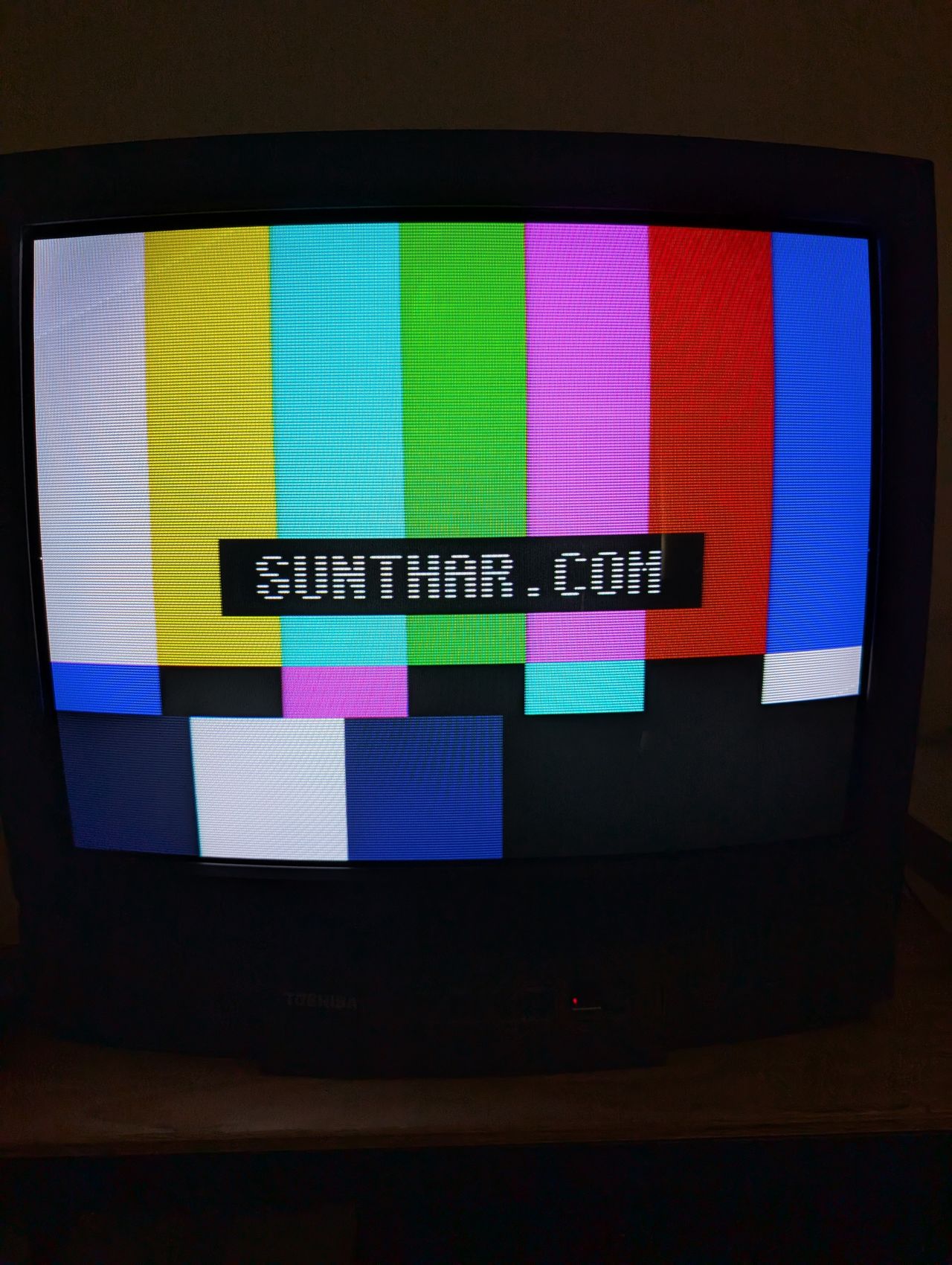
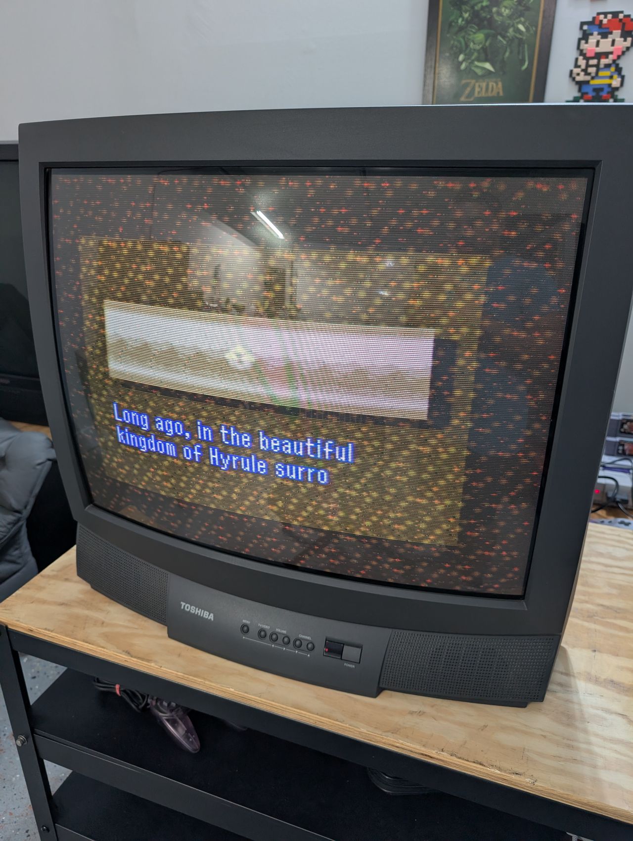
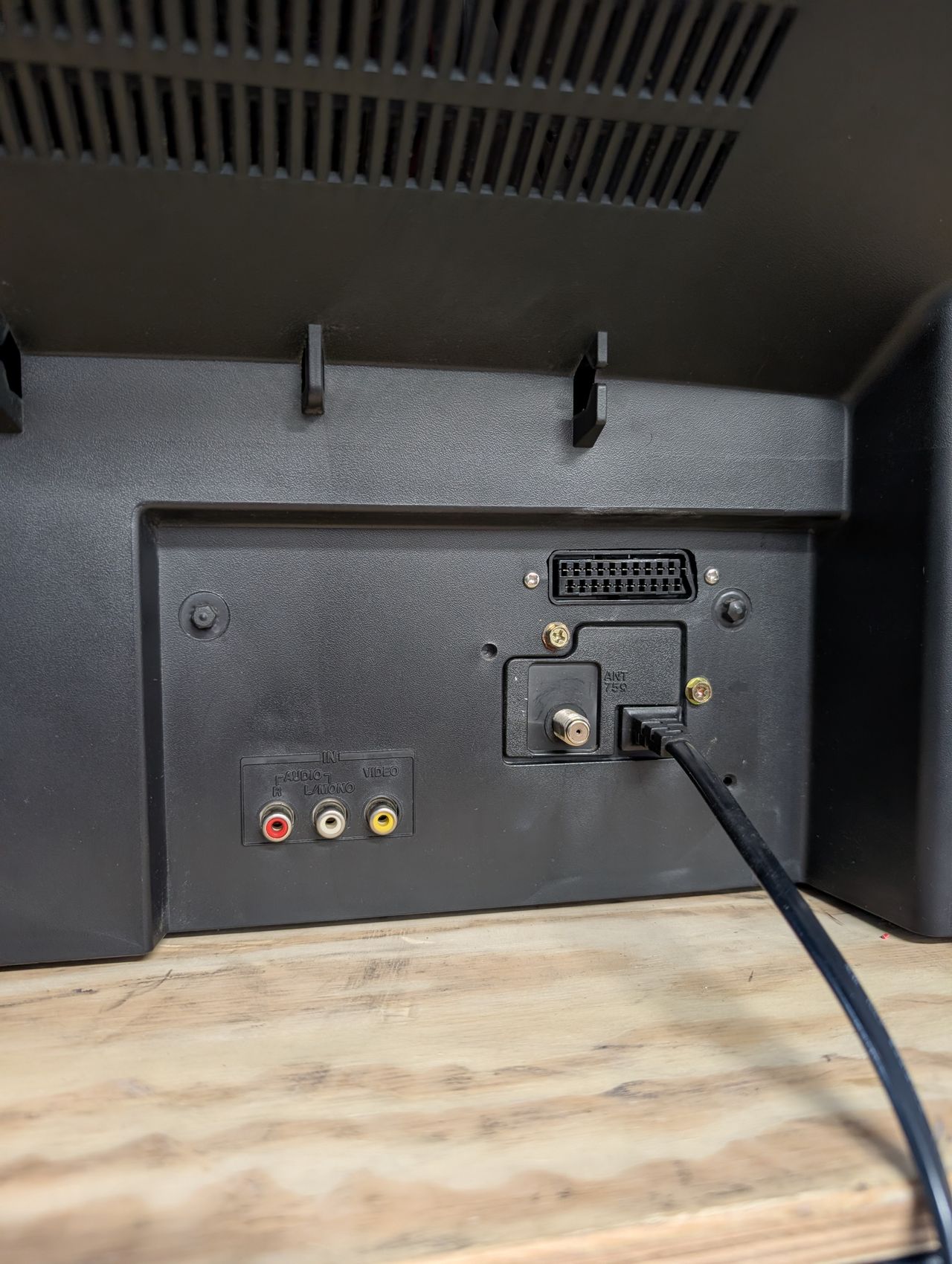
The Toshiba 27A30 is a 27" curved-tube CRT television released around 2000. It is highly regarded for its excellent geometry, reliable color reproduction, and classic analog aesthetic.
Fortunately, this set is RGB moddable.
View full CRT details and more mod examples →
Contributors
Thank you to everyone who contributed to this guide:
- Michael Lopez — showcase author
CRT safety
Caution
You can die doing this! So read carefully! CRT TV is not a toy. Do not open a CRT TV. If you don't have any prior knowledge about handling high voltage devices, this guide is not for you. CRT TV contains high enough voltage (20,000+ V) and current to be deadly, even when it is turned off.
Plan of attack
Manuals and Datasheets
Specs
- Chassis: N0ES
- Jungle Chip: Toshiba TA1223AN
- OSD Chip: TMPA8700CMN
- Screen Size: 27"
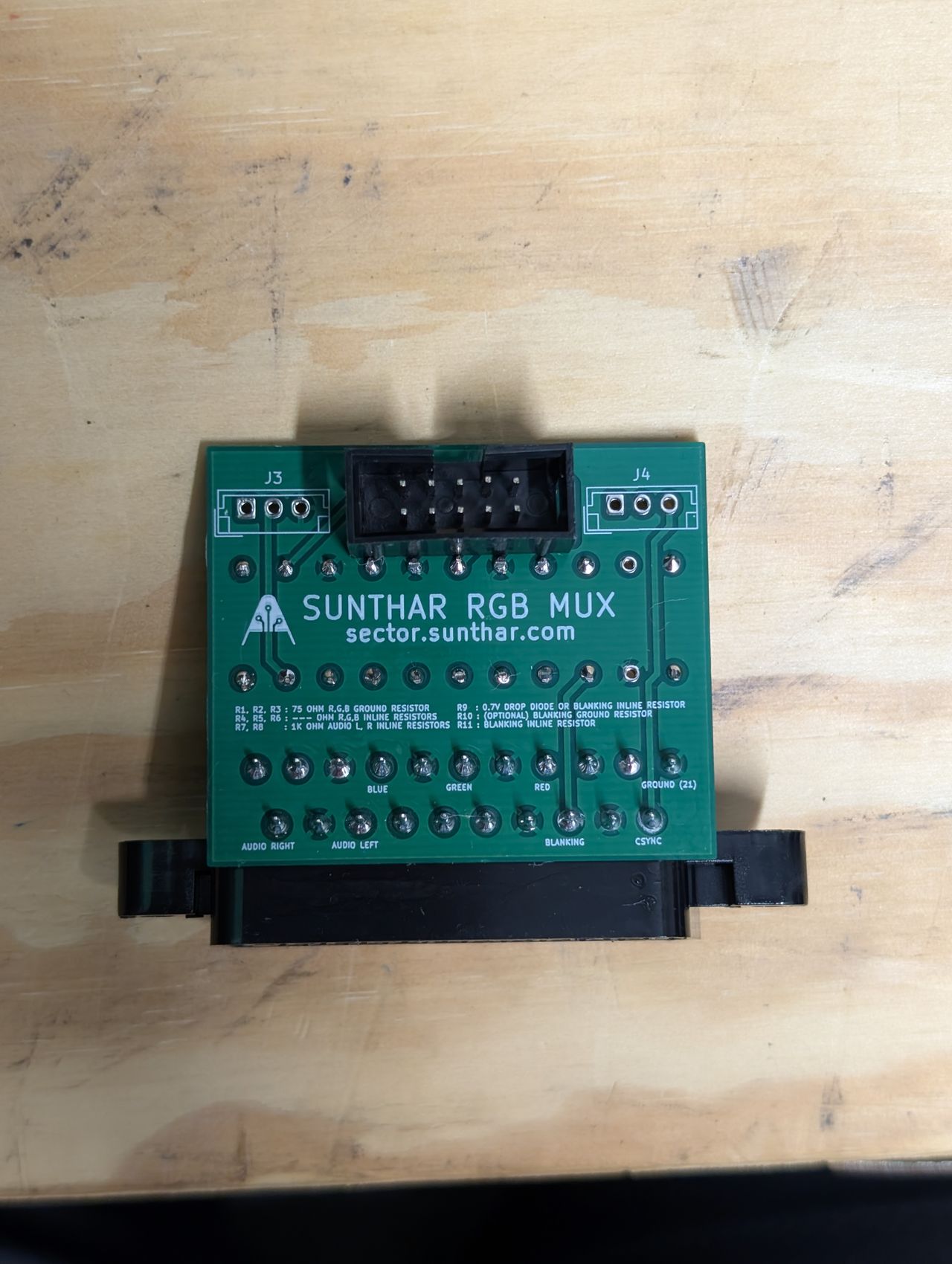
RGB mux diagram
Prepare the mux diagram. If you are building your own circuit, this diagram should help.
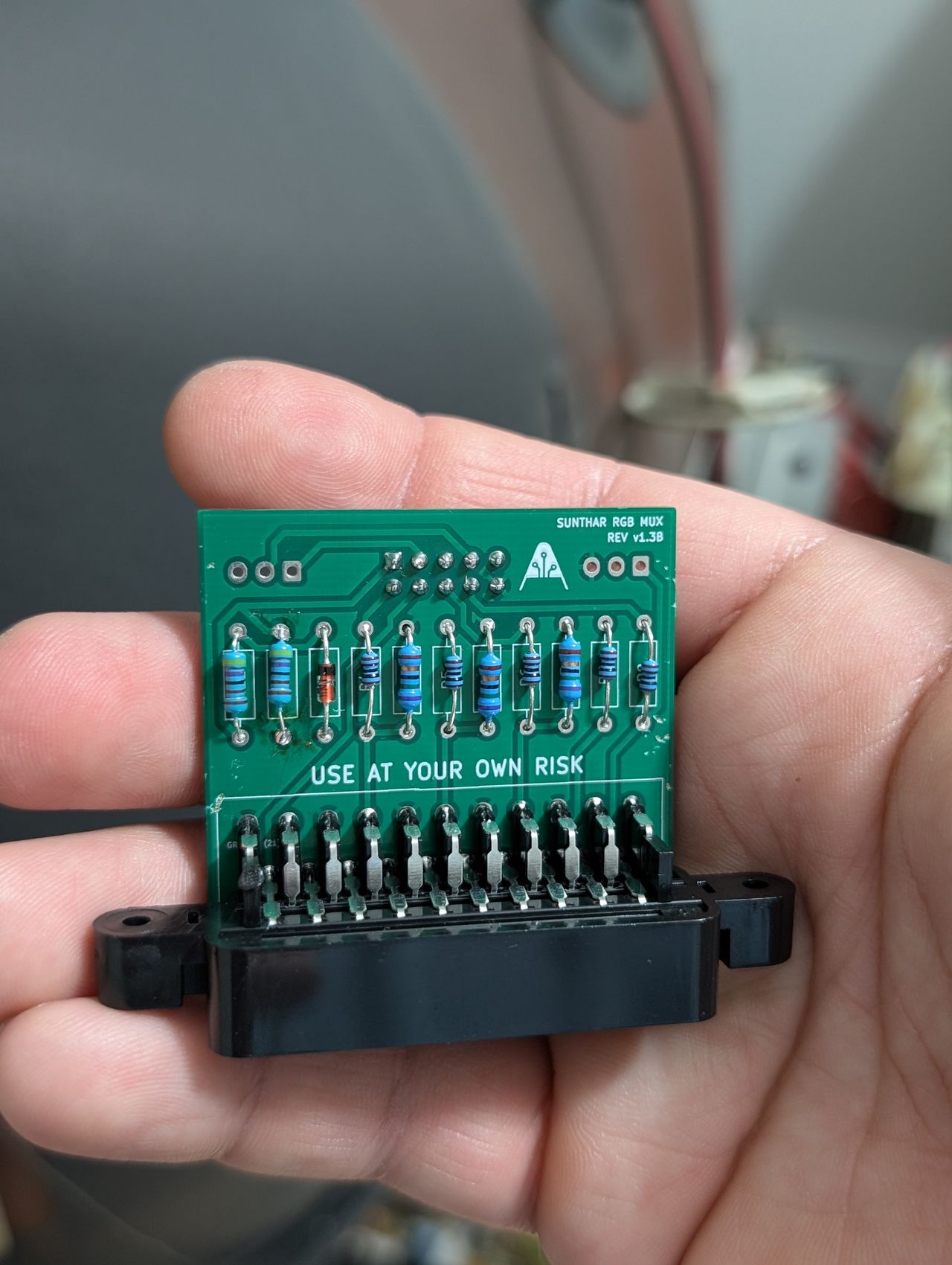
This mod uses the RGB mux board. This is optional, but will make your mod easier and stable. You can also create the circuit presented in the schematics above without the board. Please also checkout the mux calculator to play with your own values.
| On Toshiba CRT Chassis | 27A30 |
|---|---|
| CRT RGB inline resistor | 4.7kΩ |
| CRT RGB ground resistors removed | 1.2kΩ |
| 0.1μF caps replaced | Yes |
| Add diodes on chassis RGB lines? | No |
| Add blanking diode on chassis | Yes |
| RGB mux board | 27A30 |
|---|---|
| Mux board RGB termination (R1, R2, R3) | 75Ω |
| Mux board RGB inline resistors (R4, R5, R6) | 1kΩ |
| Mux board Audio LR (R7, R8) | 1kΩ |
| Mux board blanking diode (R9) | 1N4148 |
| Mux board blanking ground resistor (R10) | open |
| Mux board blanking resistor (R11) | 4.7kΩ |
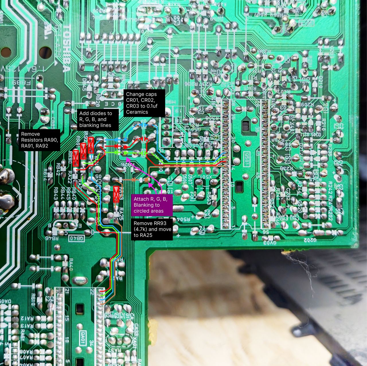
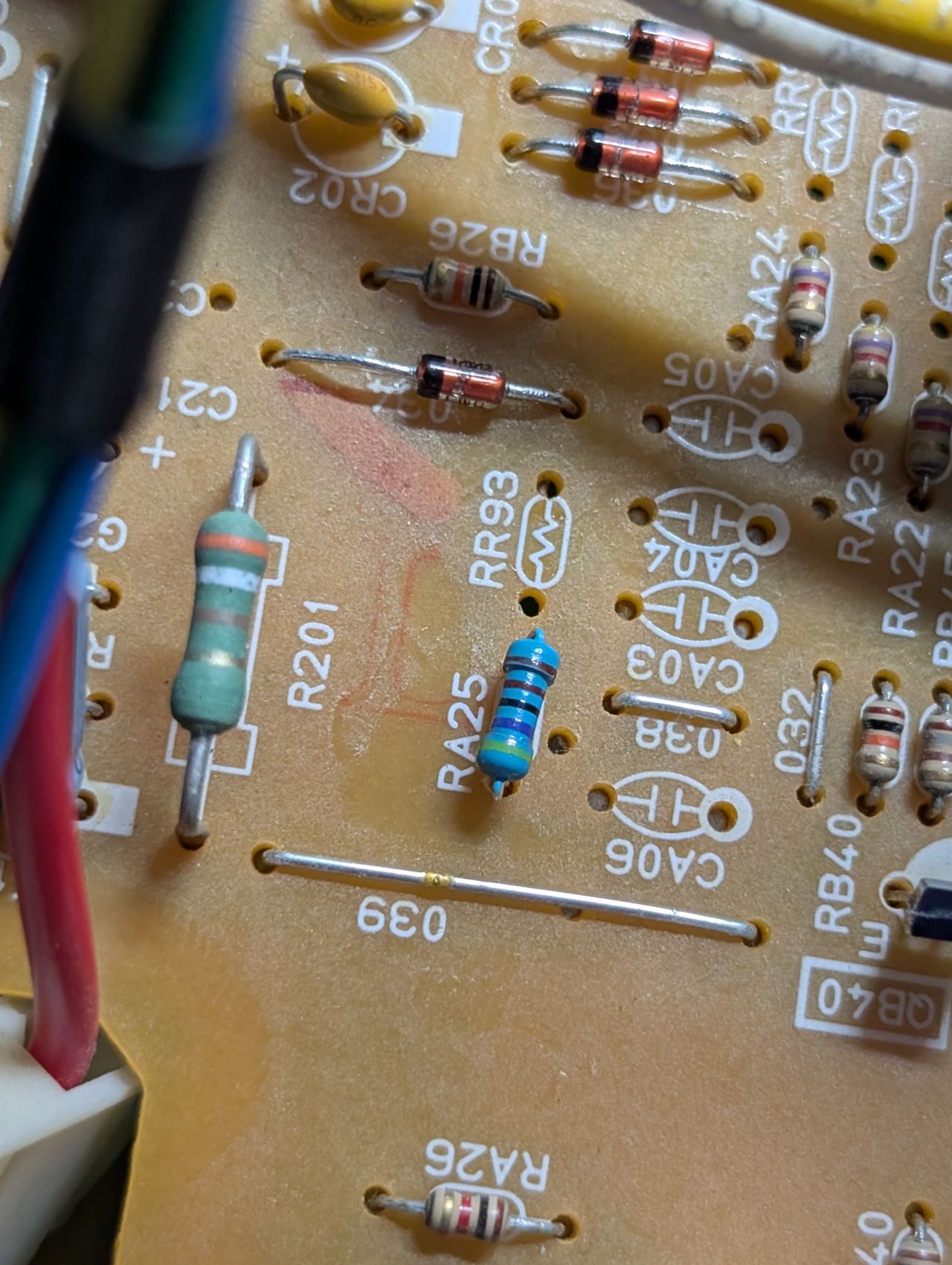
Performing the mod
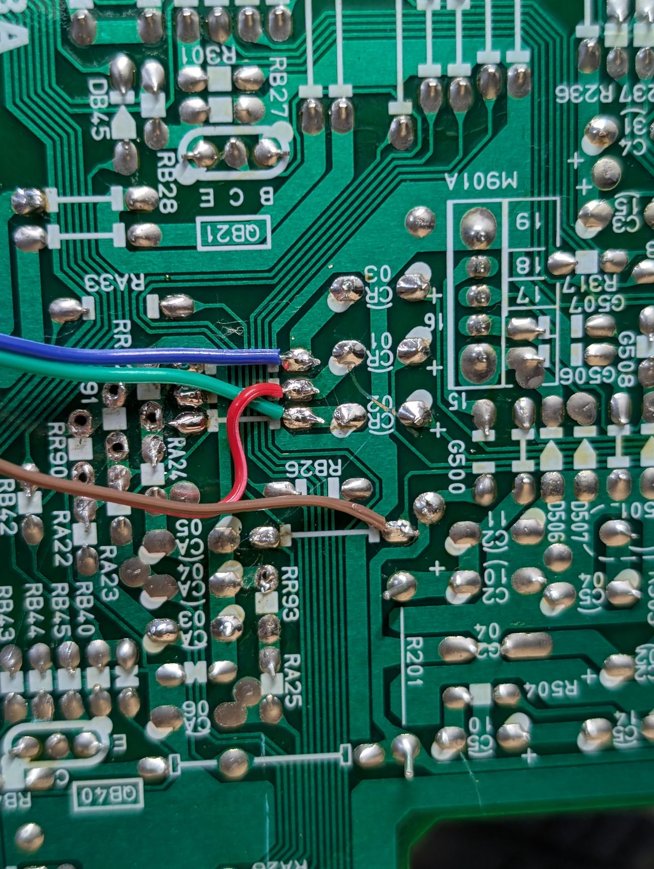
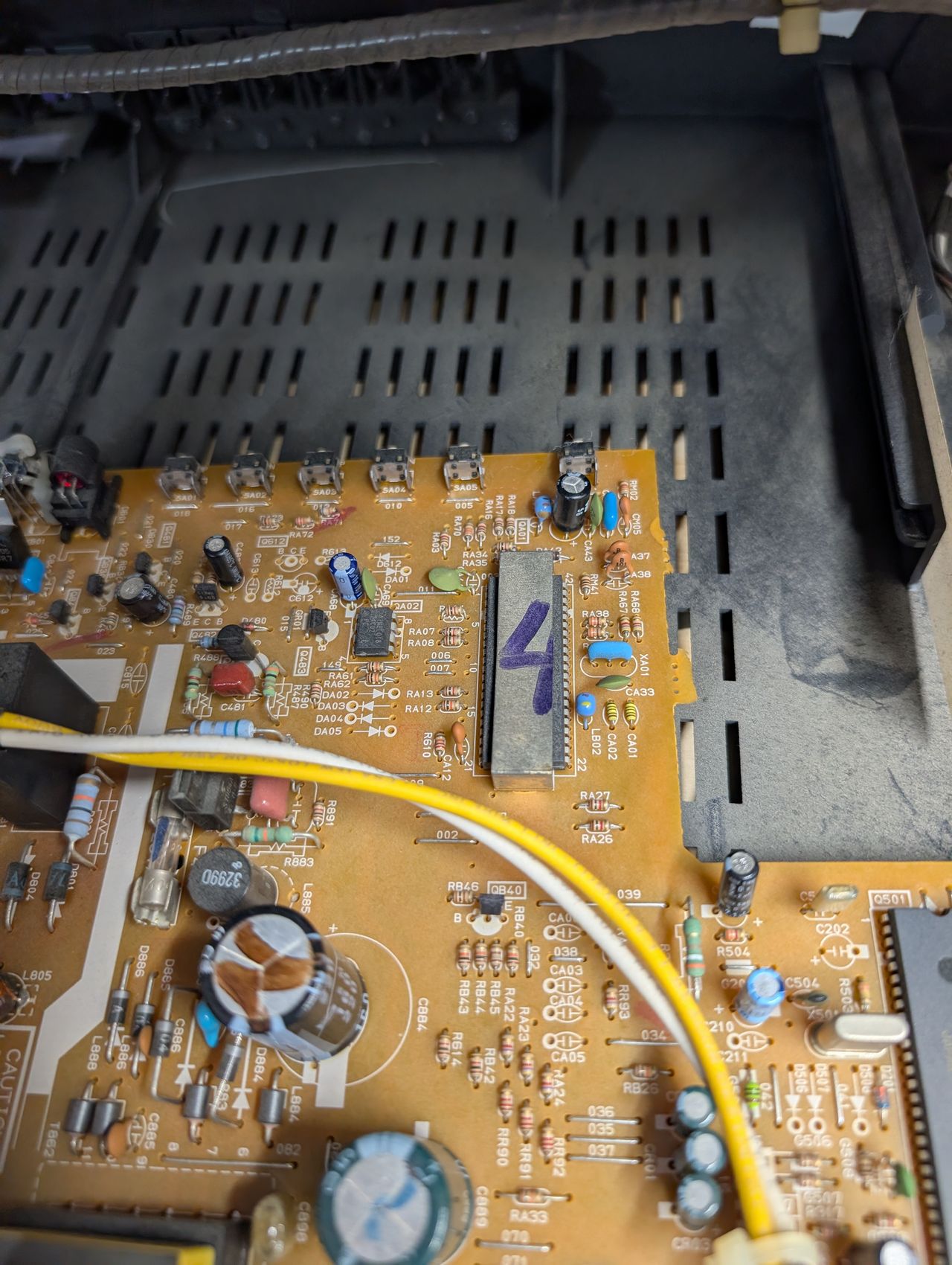
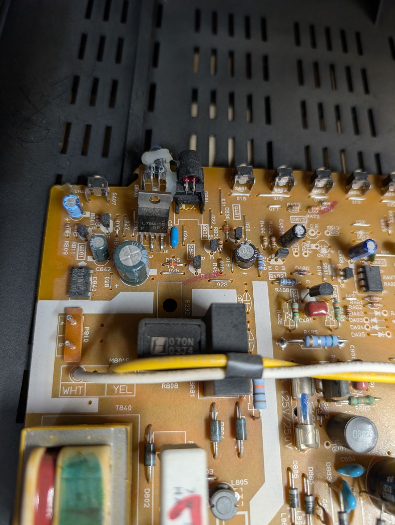
Remove RA25 (6.8kohm) and the ground resistor RR93 (4.7kohm) and replace RA25 with 4.7kohm removed from RR93.
Pictures
Photos by Michael Lopez
RGB modification showcase converted from a community support request.
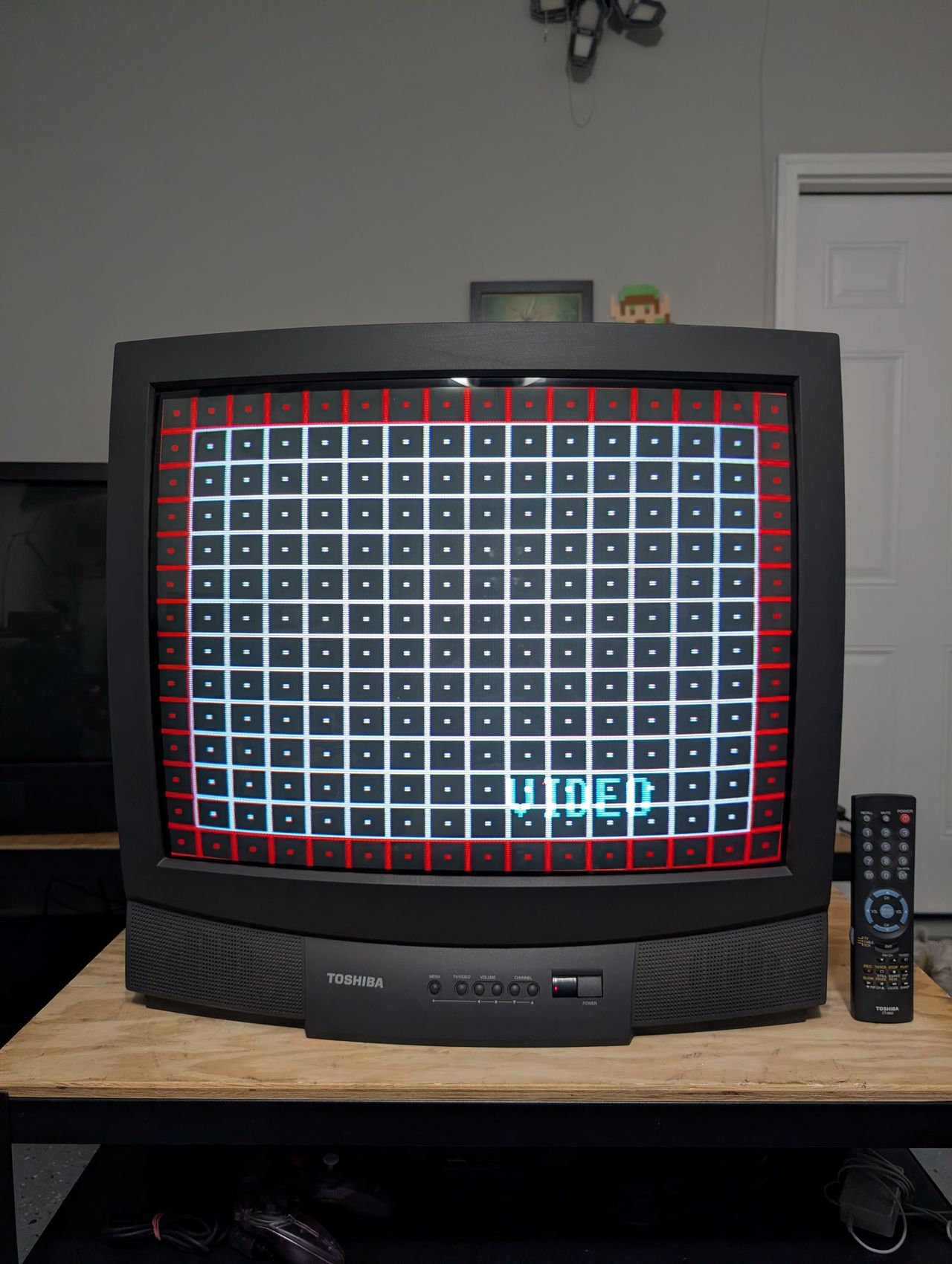
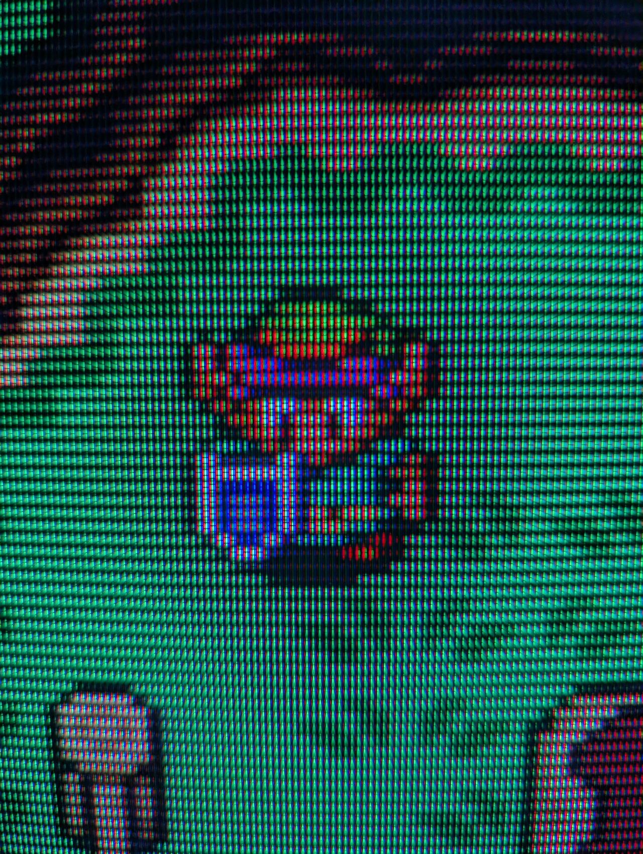
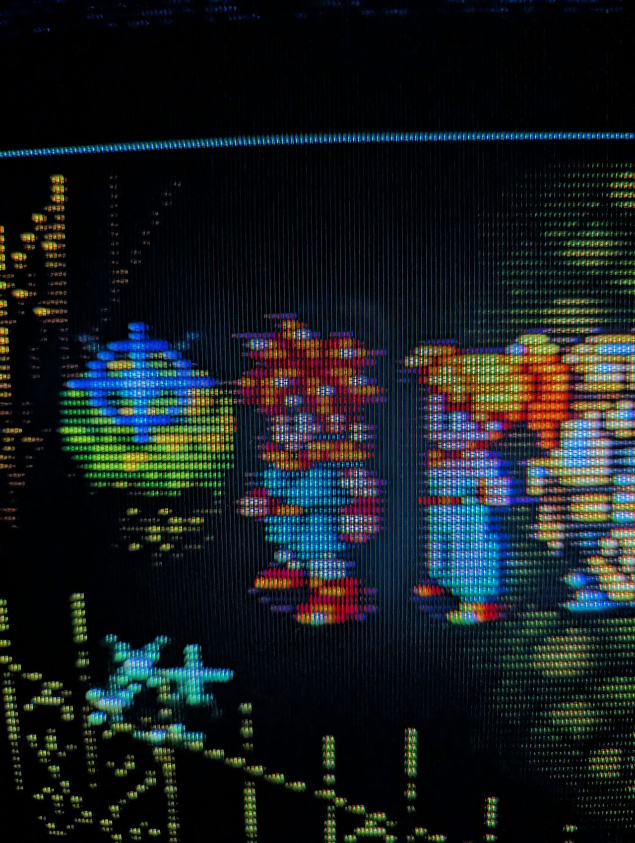

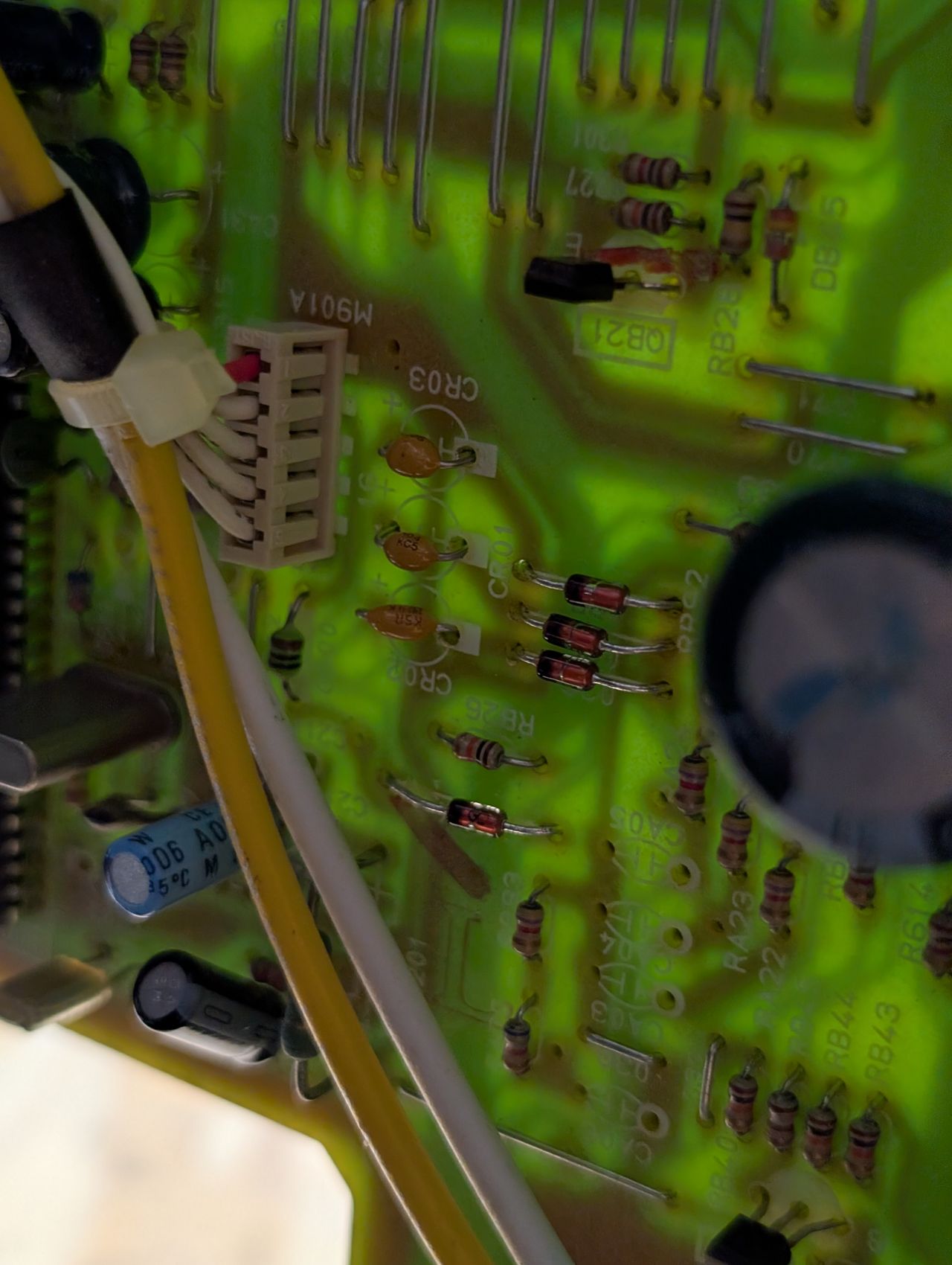
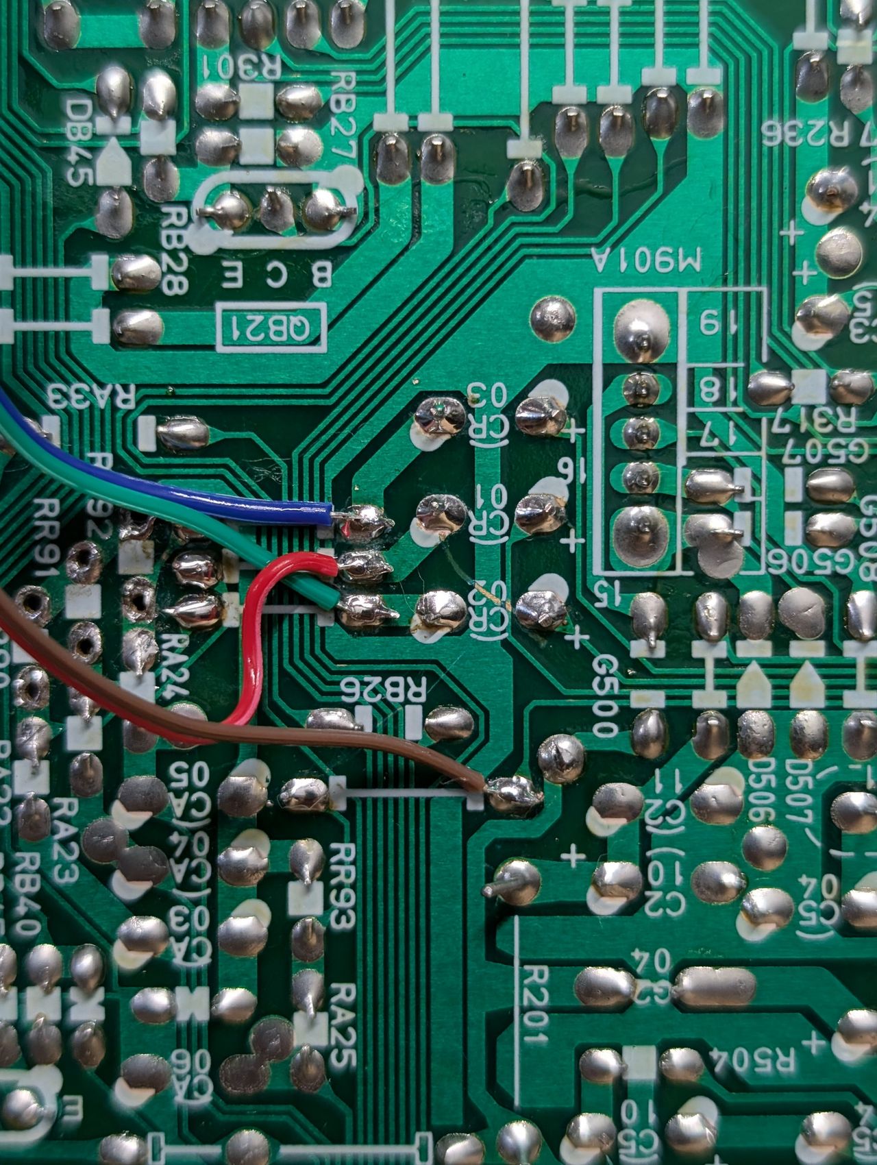
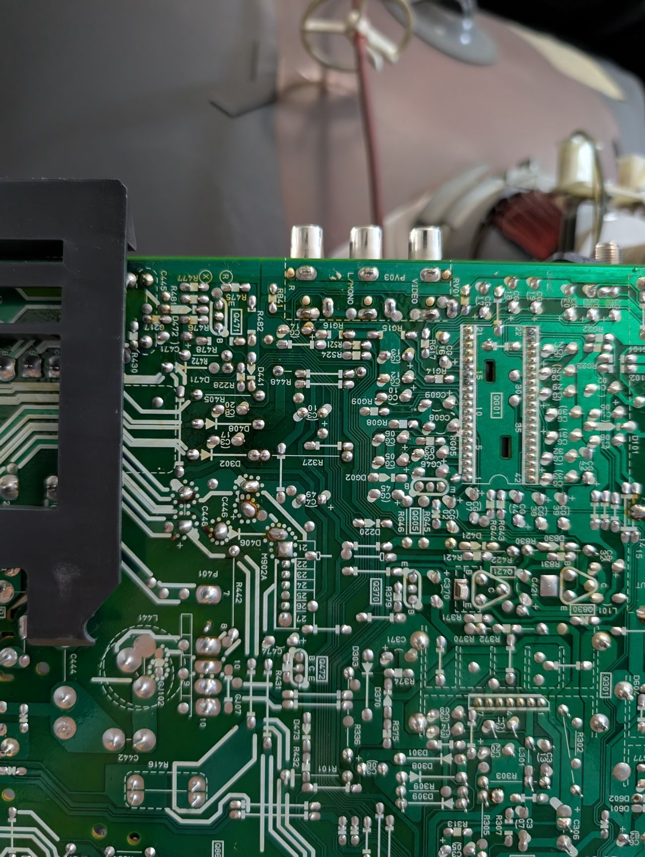
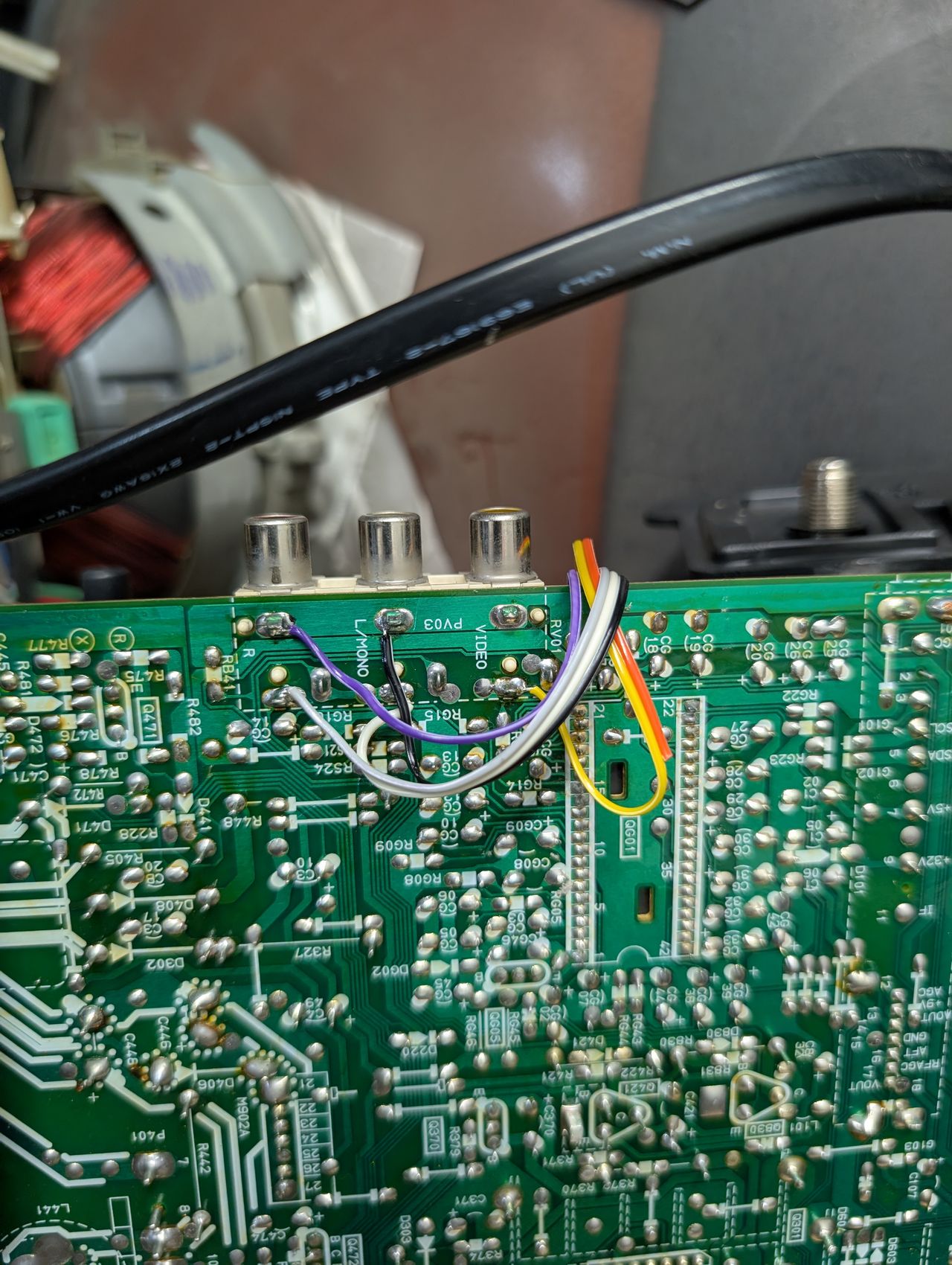
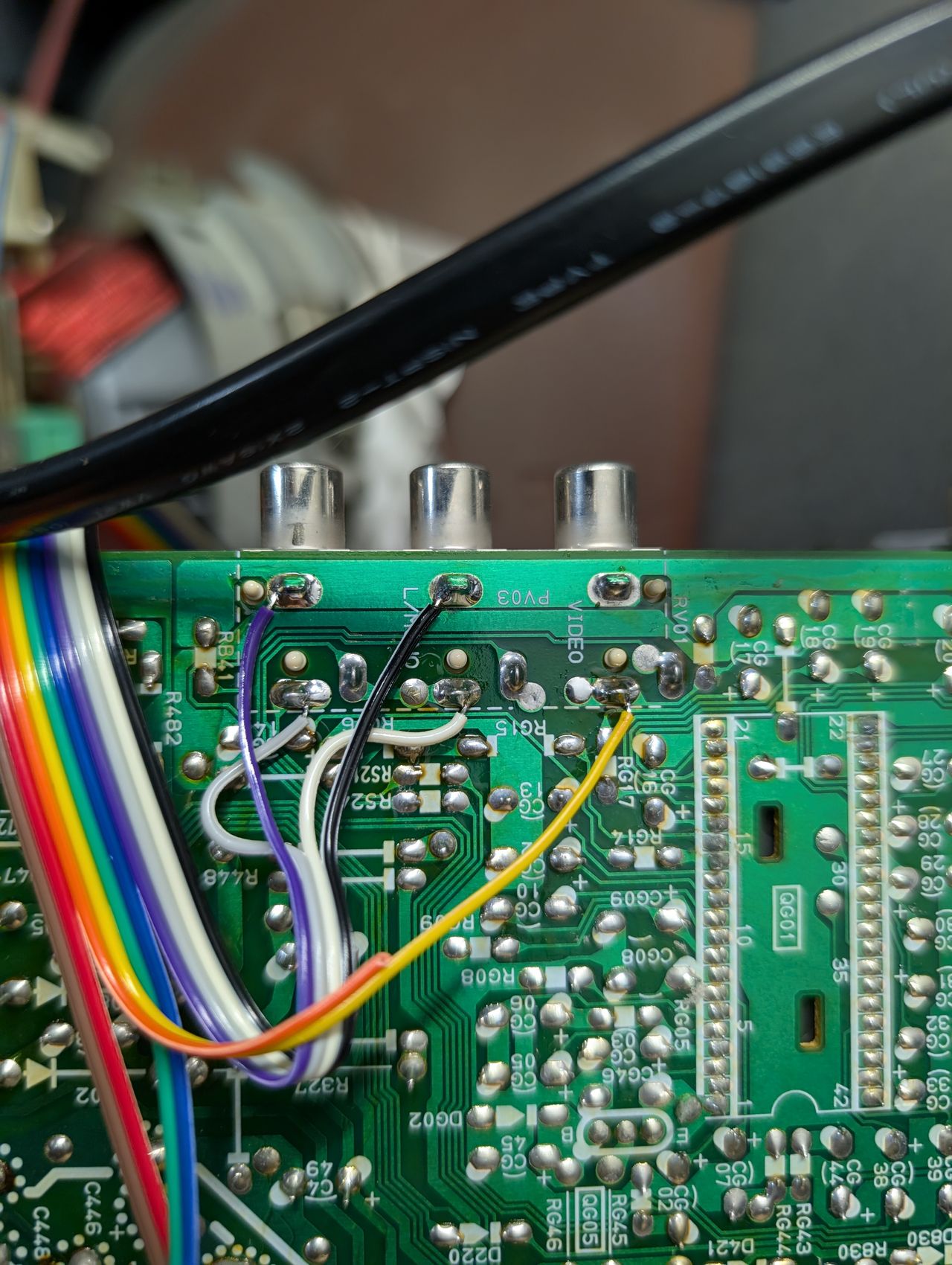
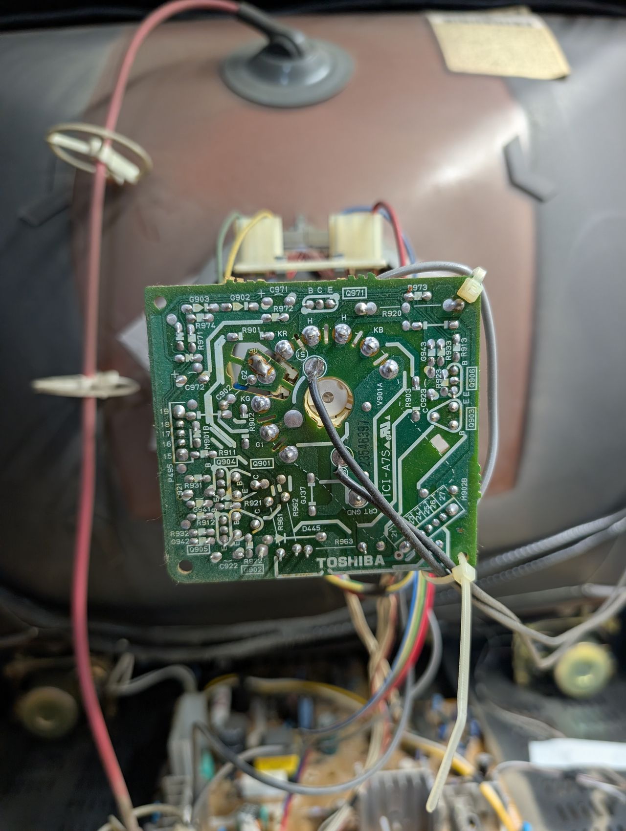
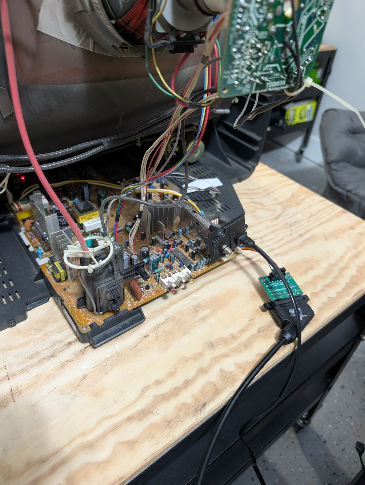

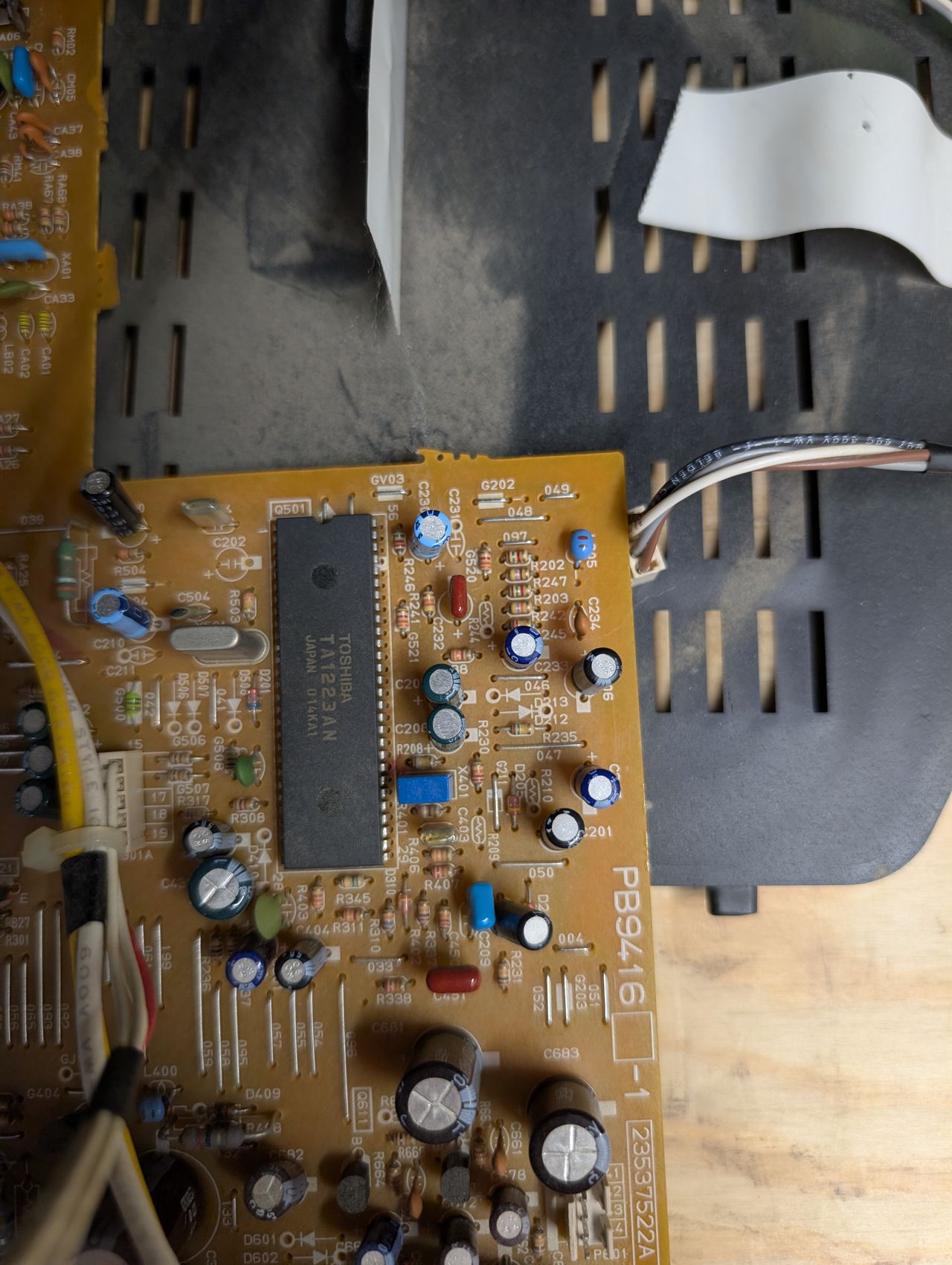
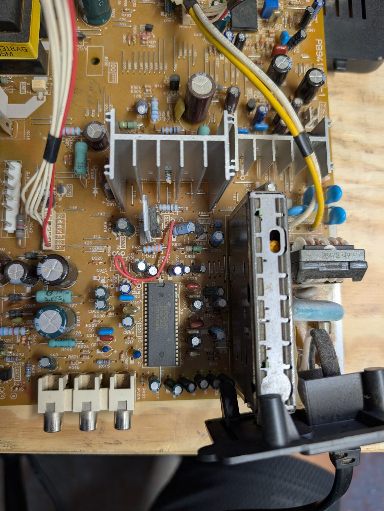
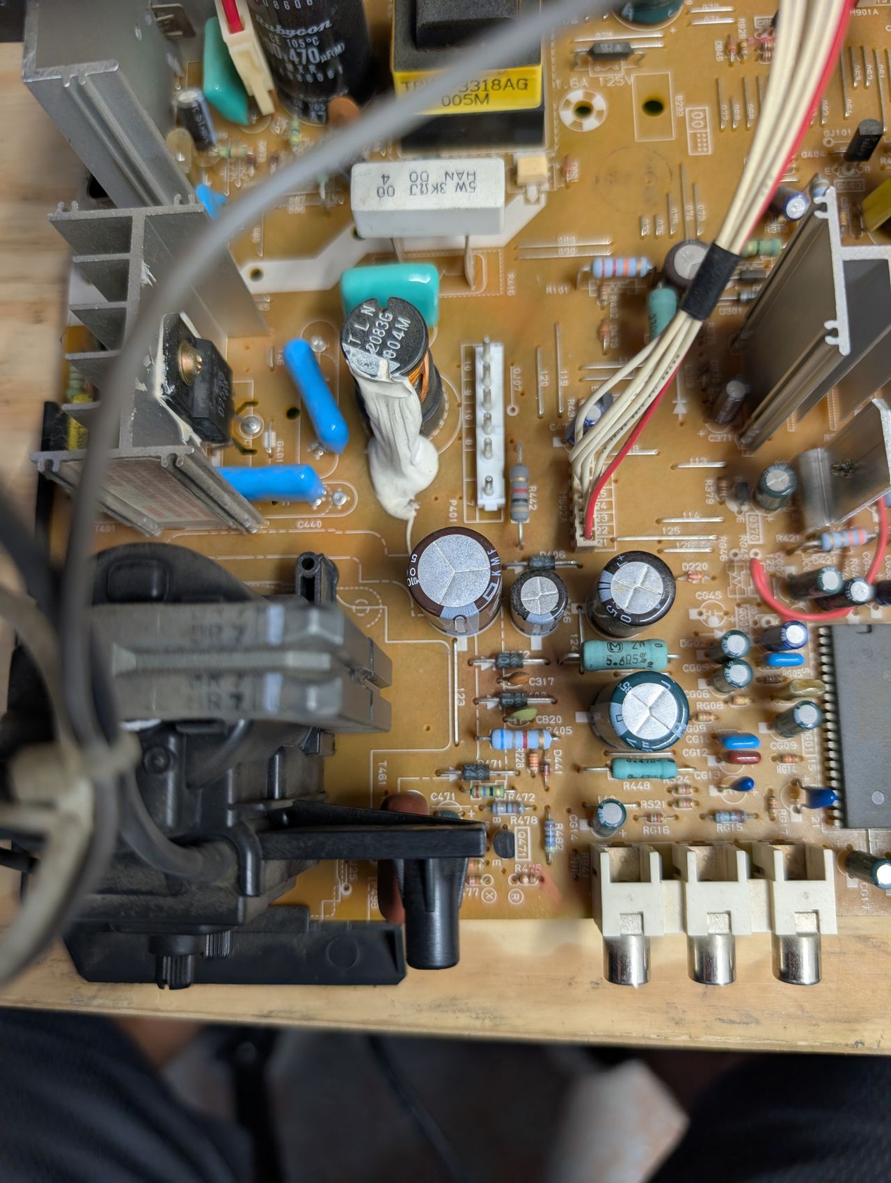
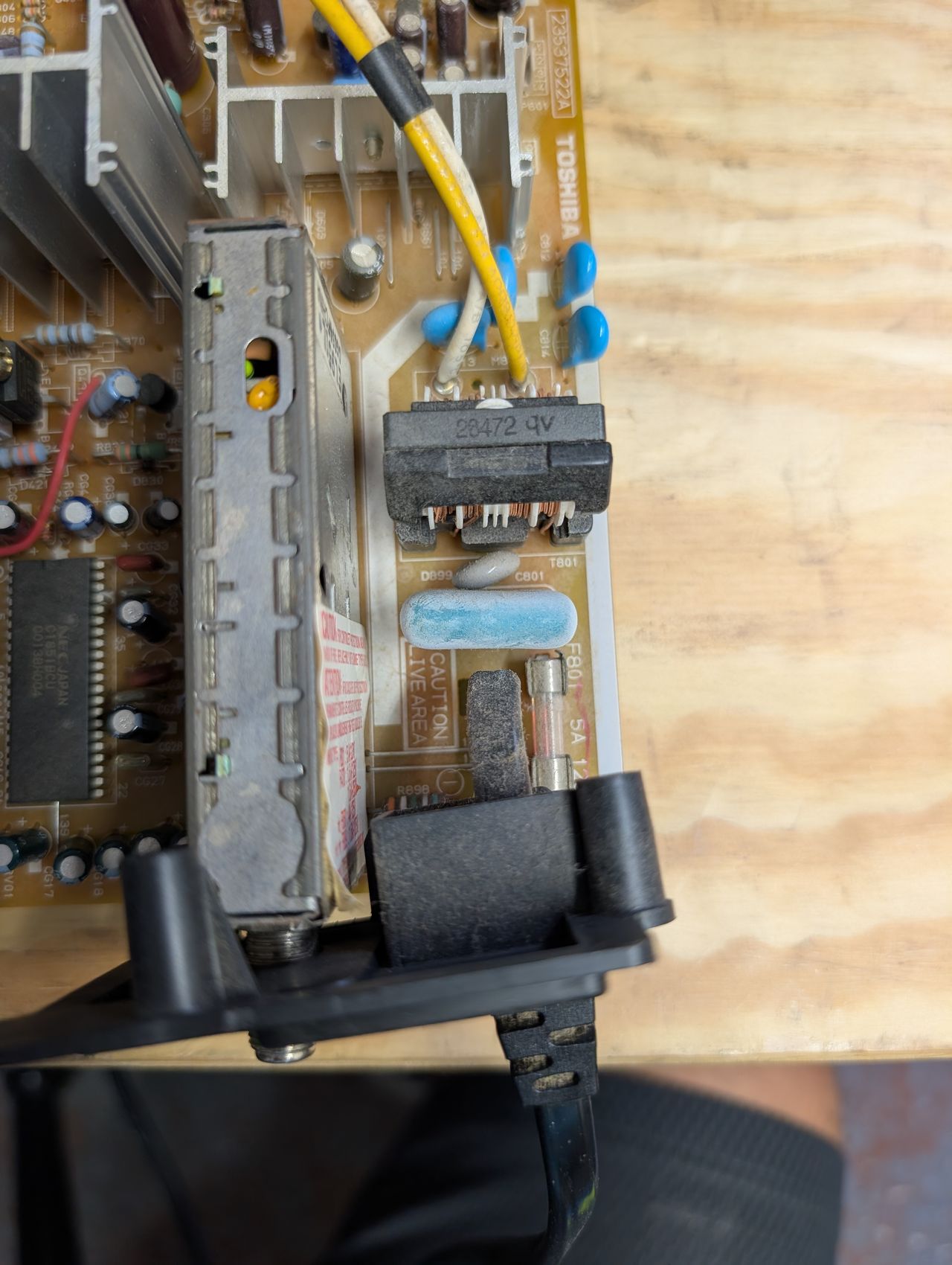
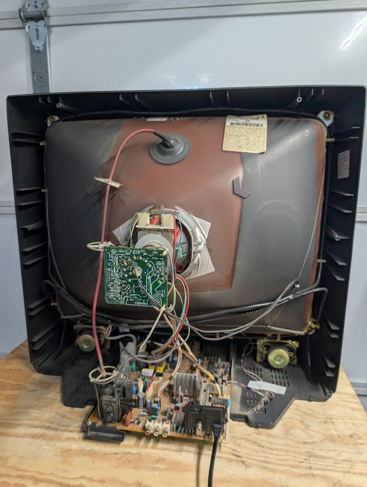
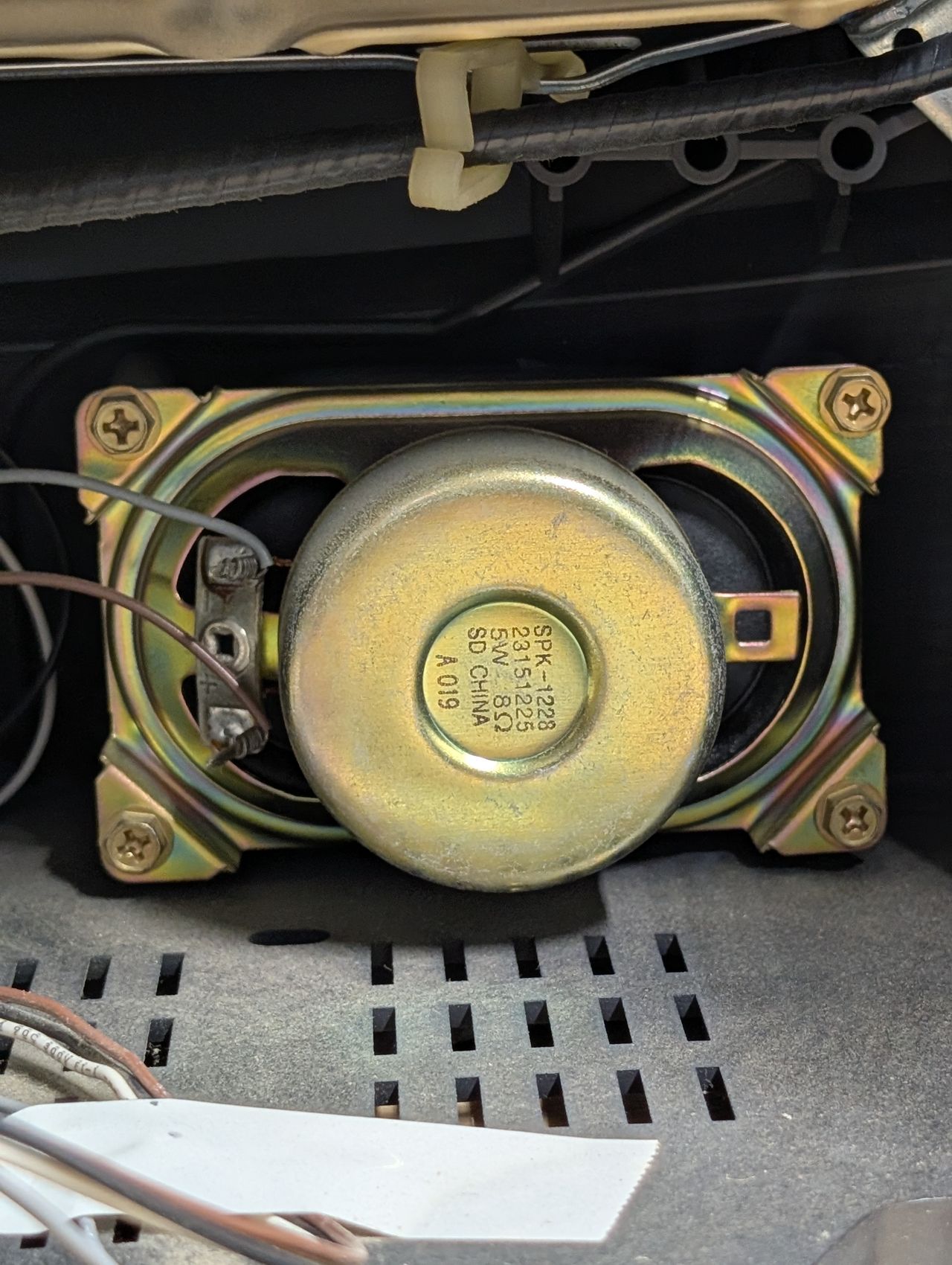
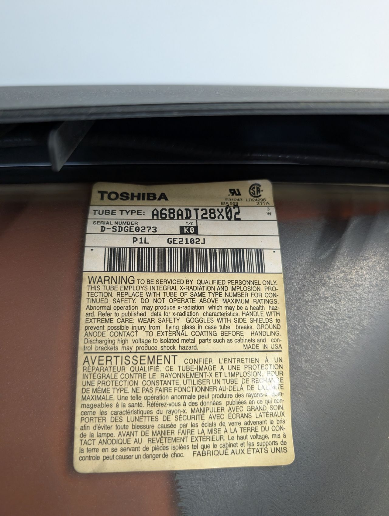
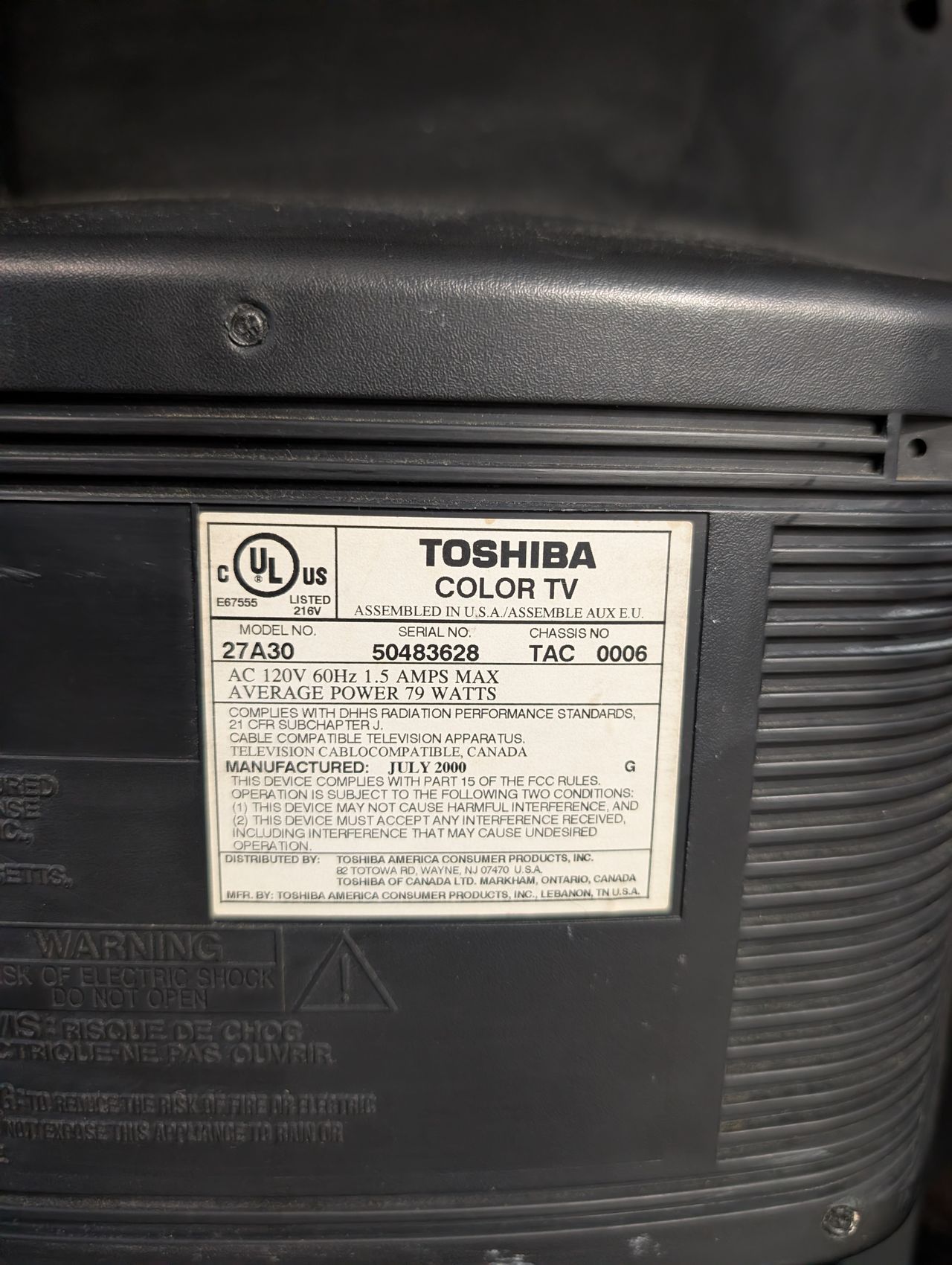
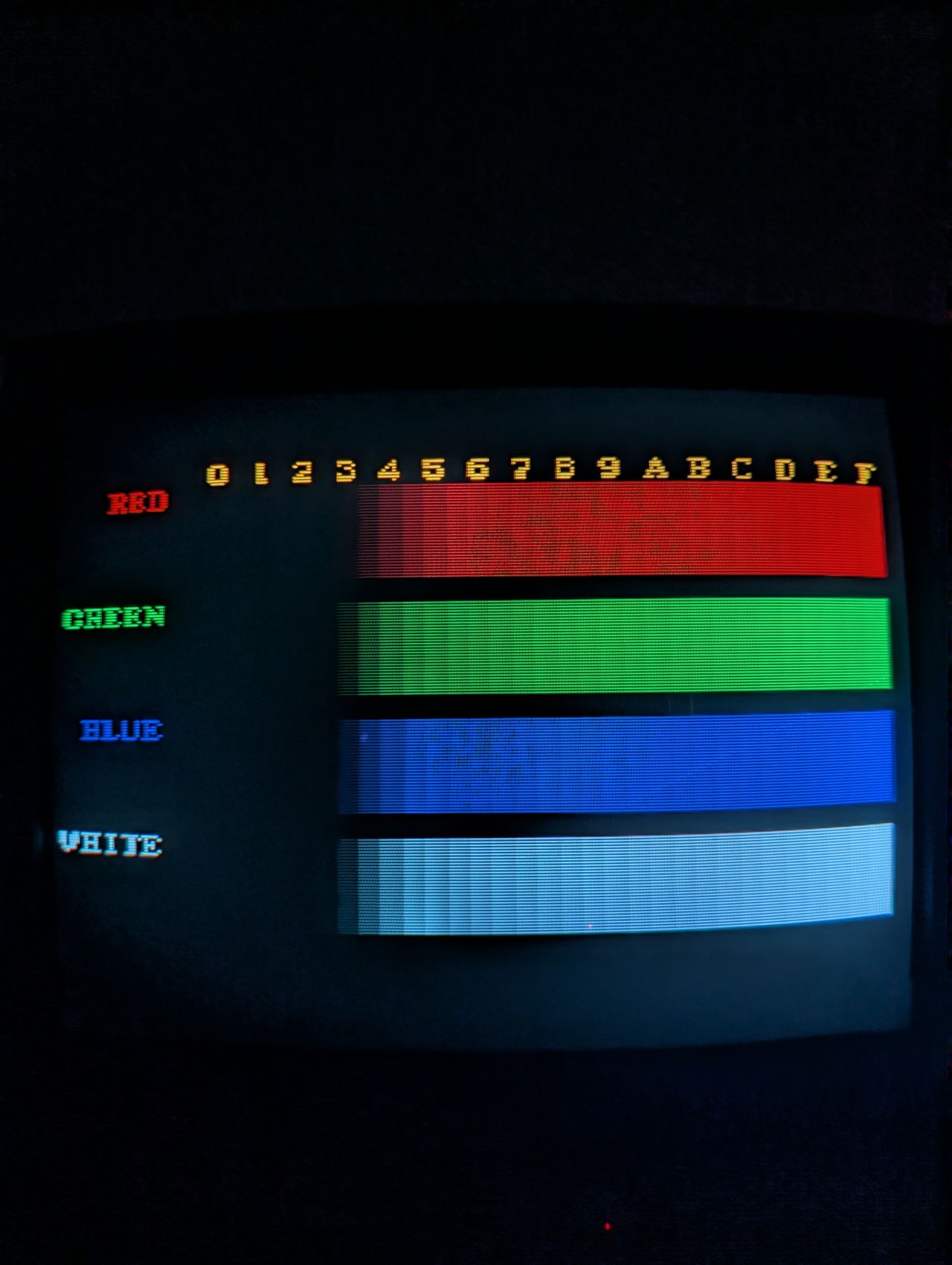
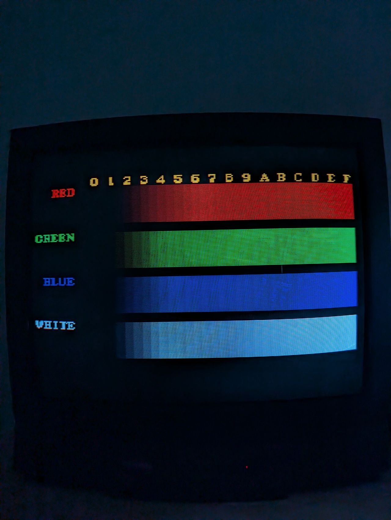
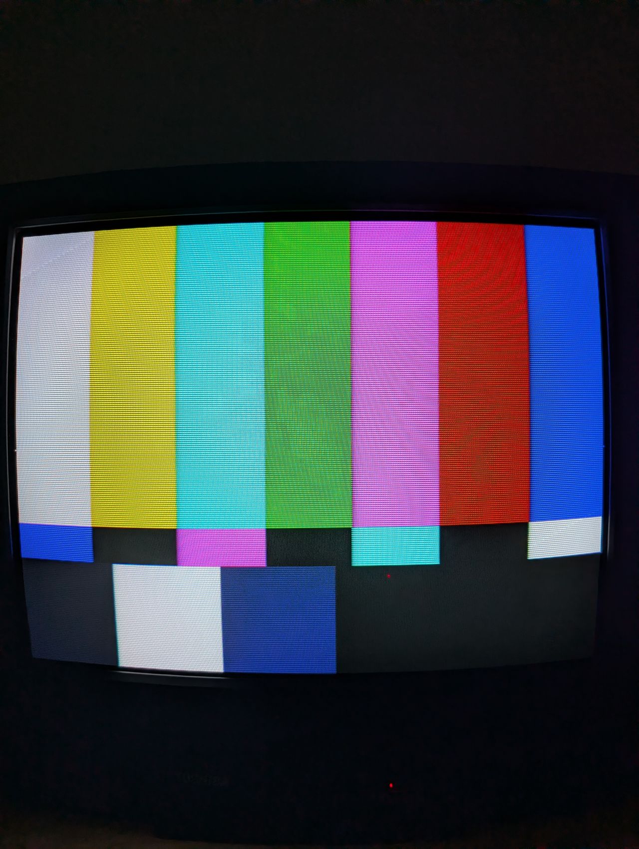
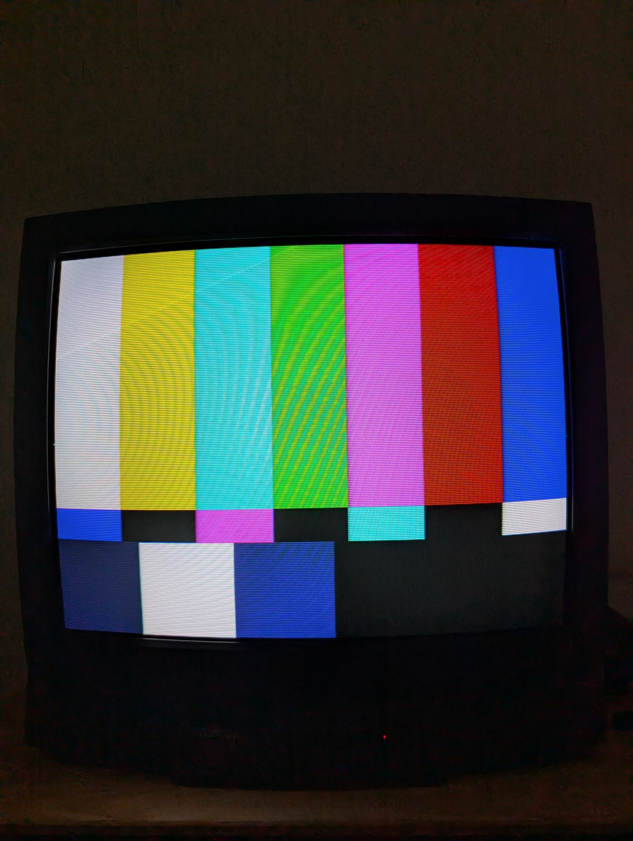
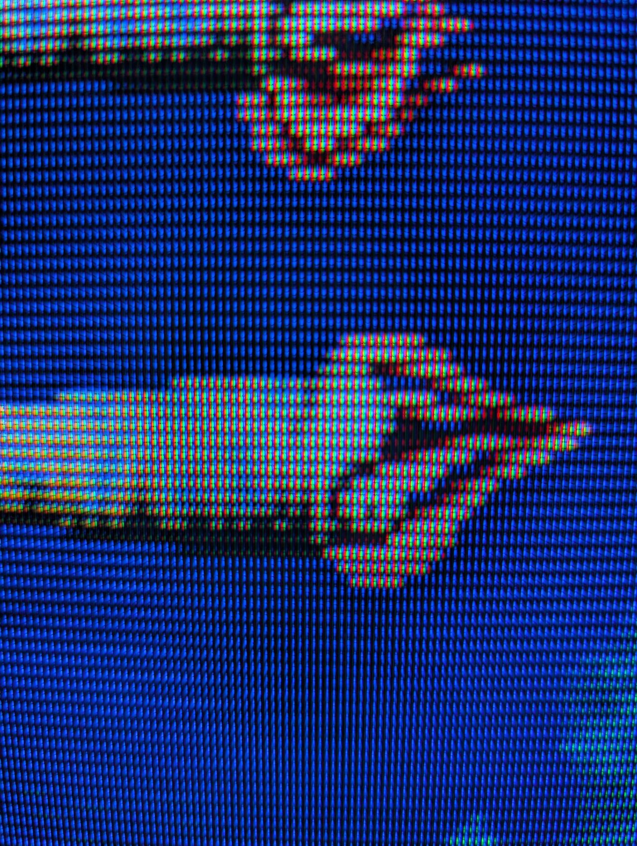
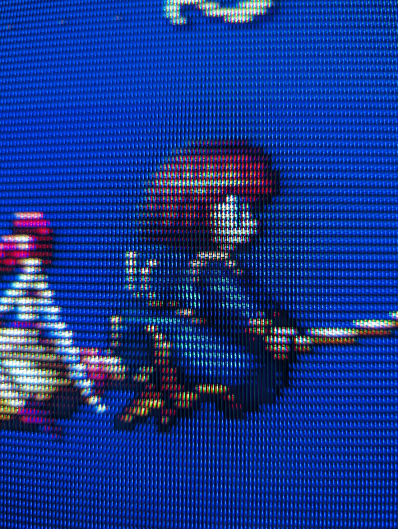

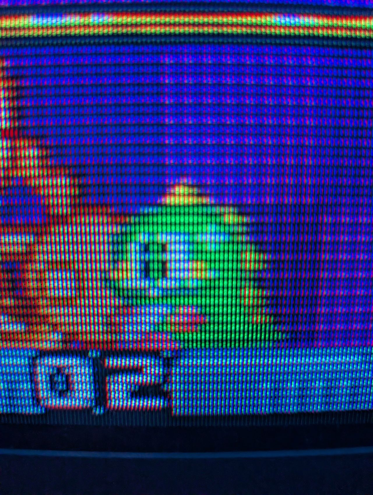
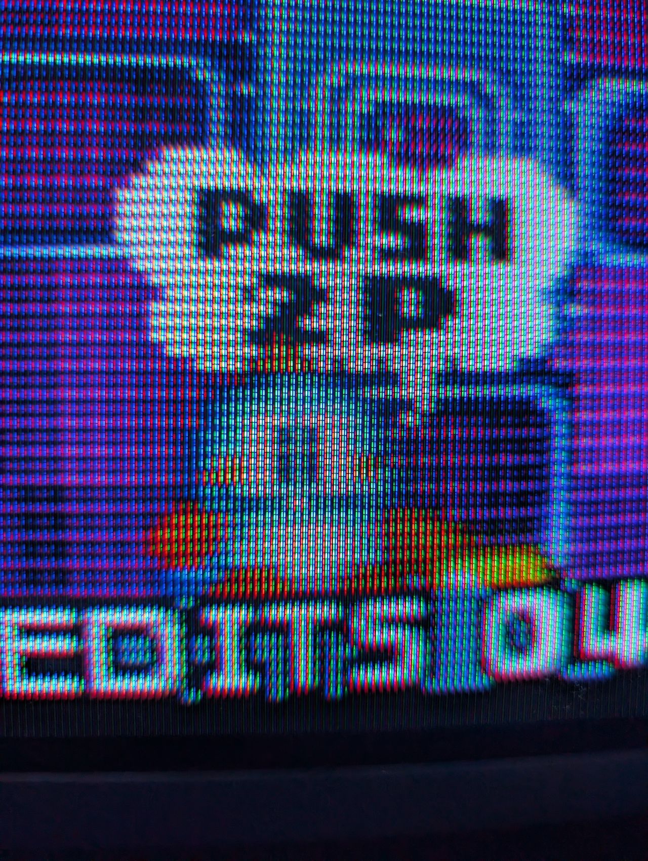
Reference Photos