JVC AV-27050
JVC AV-27050 CRT RGB mod
Note: There is a known issue with this mod, where some inputs were disabled after attempting the RGB mod.
This tutorial covers the RGB mod for JVC AV-27050.
View full CRT details and more mod examples →
Contributors
Thank you to everyone who contributed to this guide:
- Zachary Lahlou — photos and documentation
CRT safety
Caution
You can die doing this! So read carefully! CRT TV is not a toy. Do not open a CRT TV. If you don't have any prior knowledge about handling high voltage devices, this guide is not for you. CRT TV contains high enough voltage (20,000+ V) and current to be deadly, even when it is turned off.
Plan of attack
Service manuals
Specs
- Year:
- Format: NTSC
- Tube: JVC A68ADT25X01
- Jungle Chip: Toshiba TA1242N
- OSD Chip: Matsushita MN1874878JP1
- Screen Size: 27"
- Inputs: Composite, S-Video, RF
RGB mux diagram
This mod uses the RGB mux board. This is optional, but will make your mod easier and stable. You can also create the circuit presented in the schematics above without the board. Please also checkout the mux calculator to play with your own values.
| Component | Value |
|---|---|
| RGB/OSD inline resistor (chassis) | 2.2kΩ |
| Removed RGB/OSD resistor (chassis) | 470Ω |
| RGB inline diode method (chassis) | Yes |
| 0.1μF caps replaced (chassis) | Yes |
| RGB termination (R1, R2, R3) | 220Ω |
| RGB inline (R4, R5, R6) | 470Ω |
| Audio LR (R7, R8) | 1kΩ |
| Diode (R9) | 1N4148 |
| Blanking Ground Resistor (R10) | open |
| Blanking Resistor (R11) | 1kΩ |
| Transistor Base Resistor (R12) | 1kΩ |
| Transistor (Q1) | PN2222A |
Performing the mod
RGB mod for this is not yet confirmed. Values presented are all theoretical based on service manual.
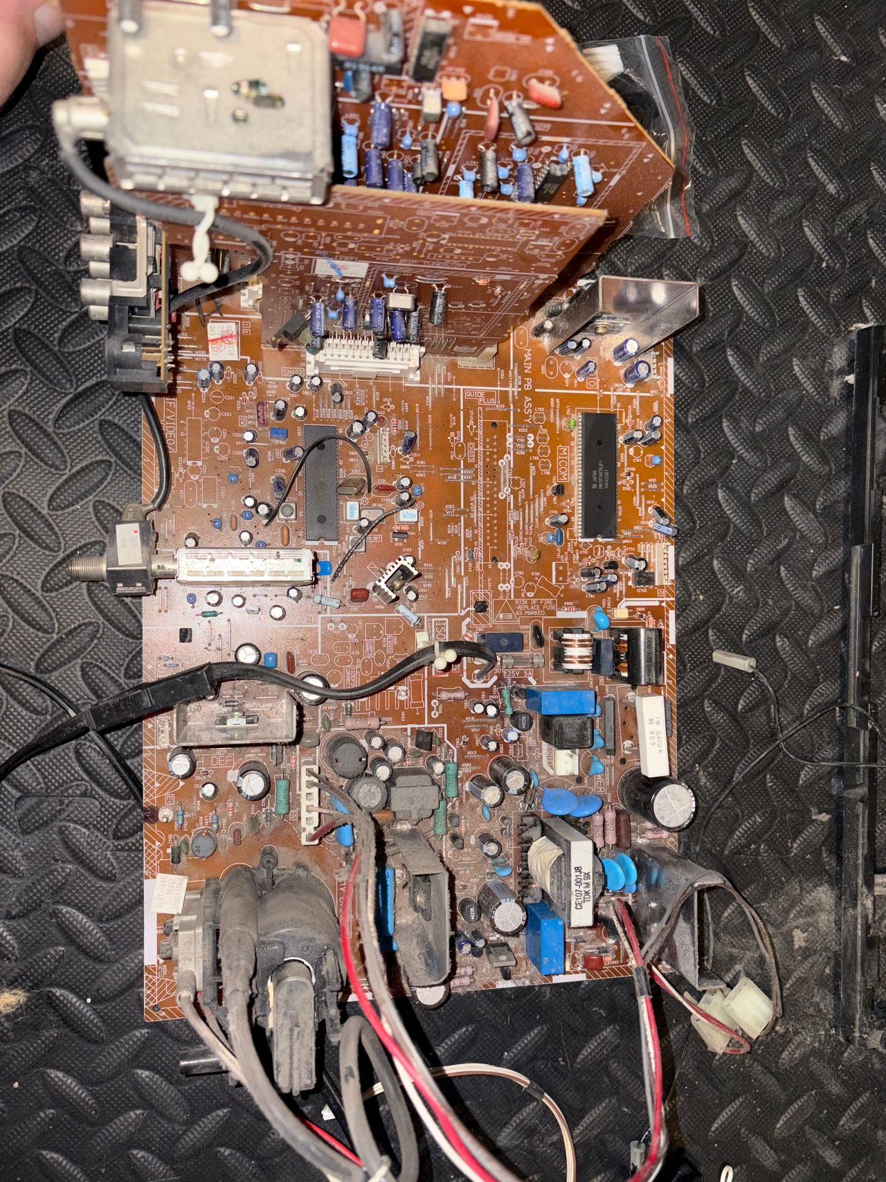
Pictures
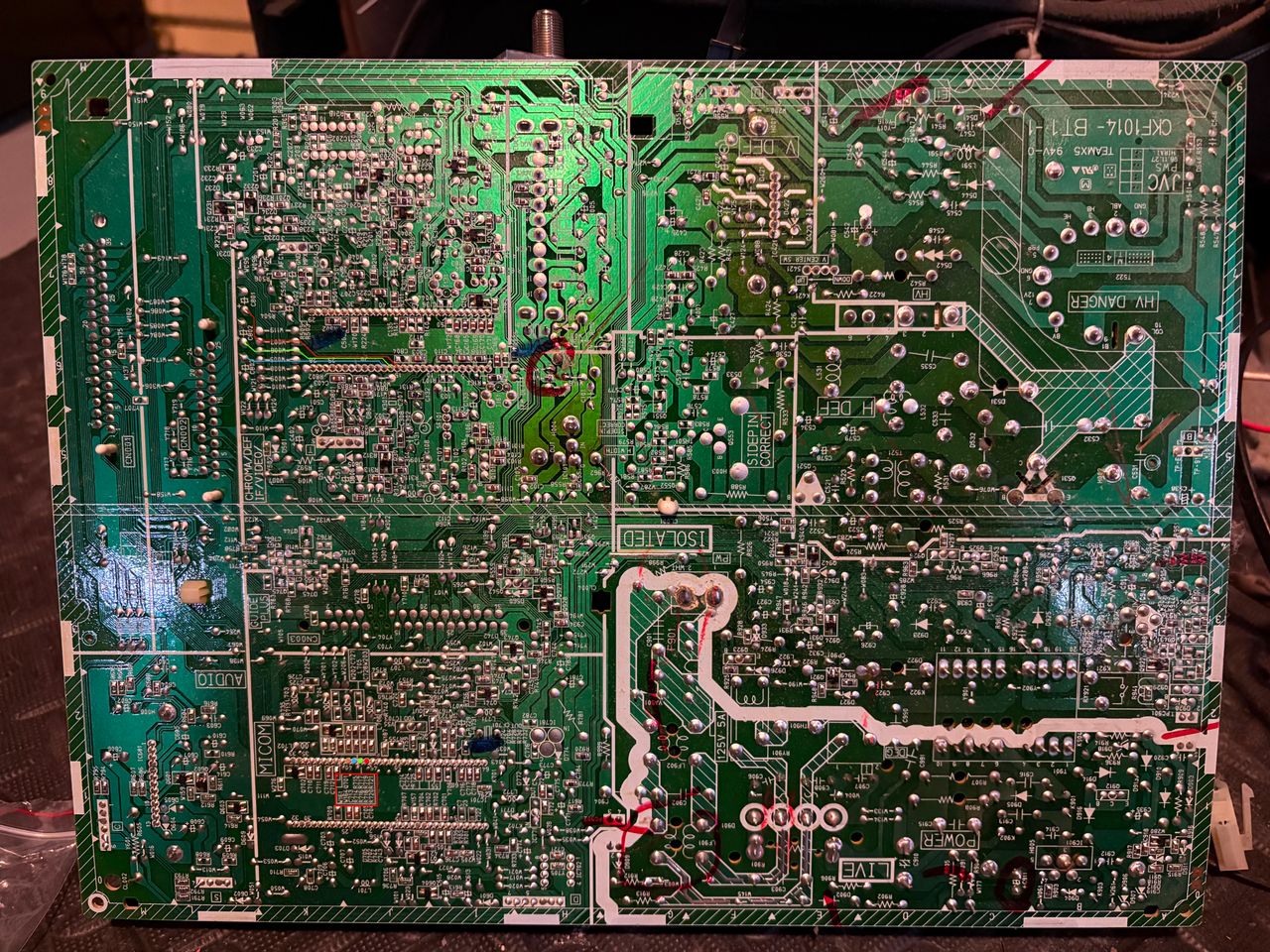
Photos by Zachary Lahlou's Sector
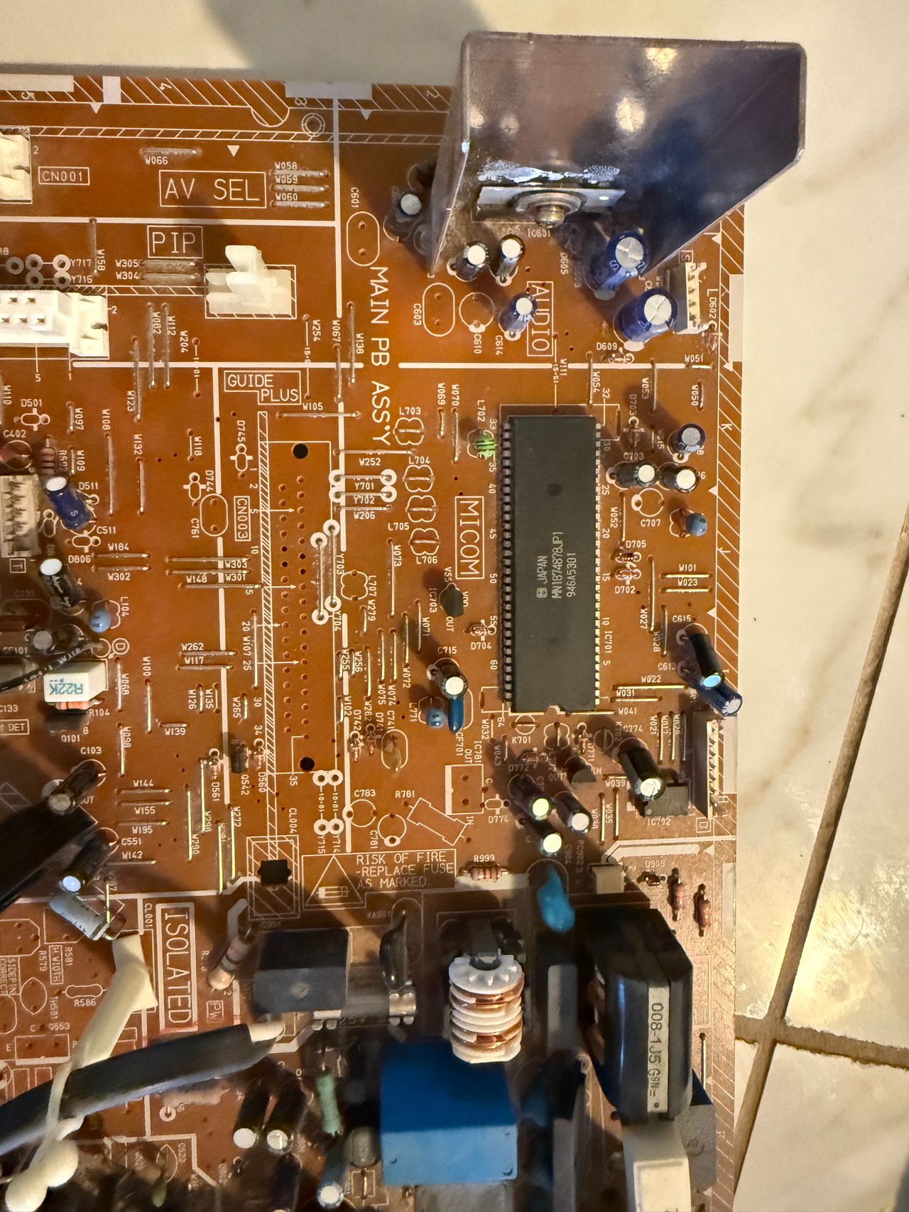
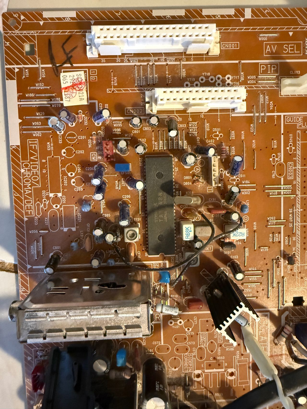
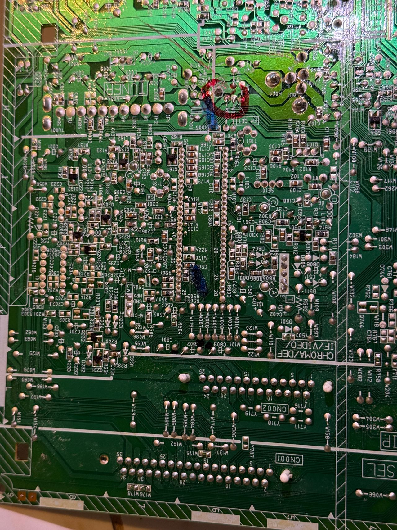
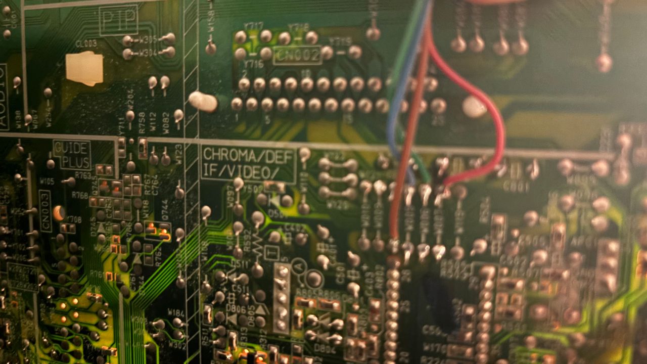
Trace side of the jungle IC
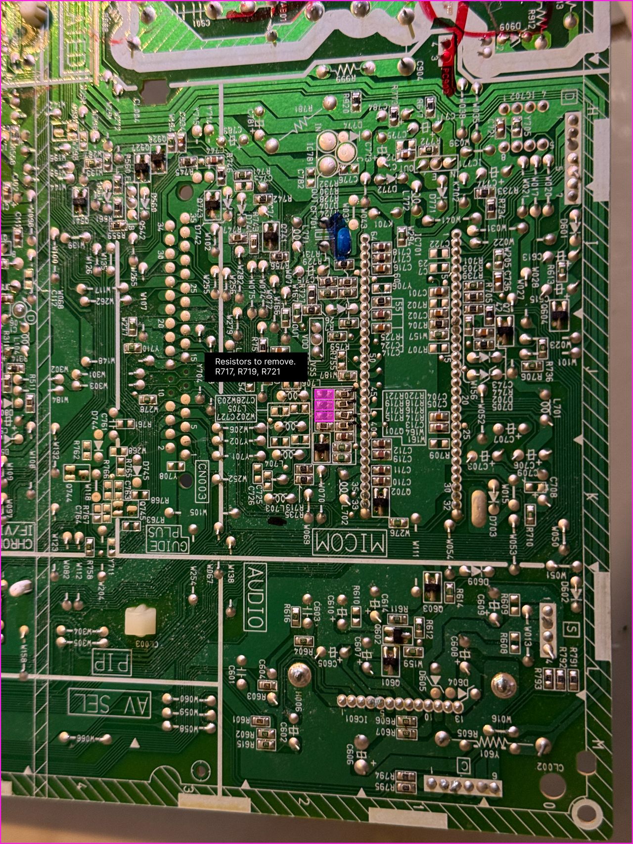
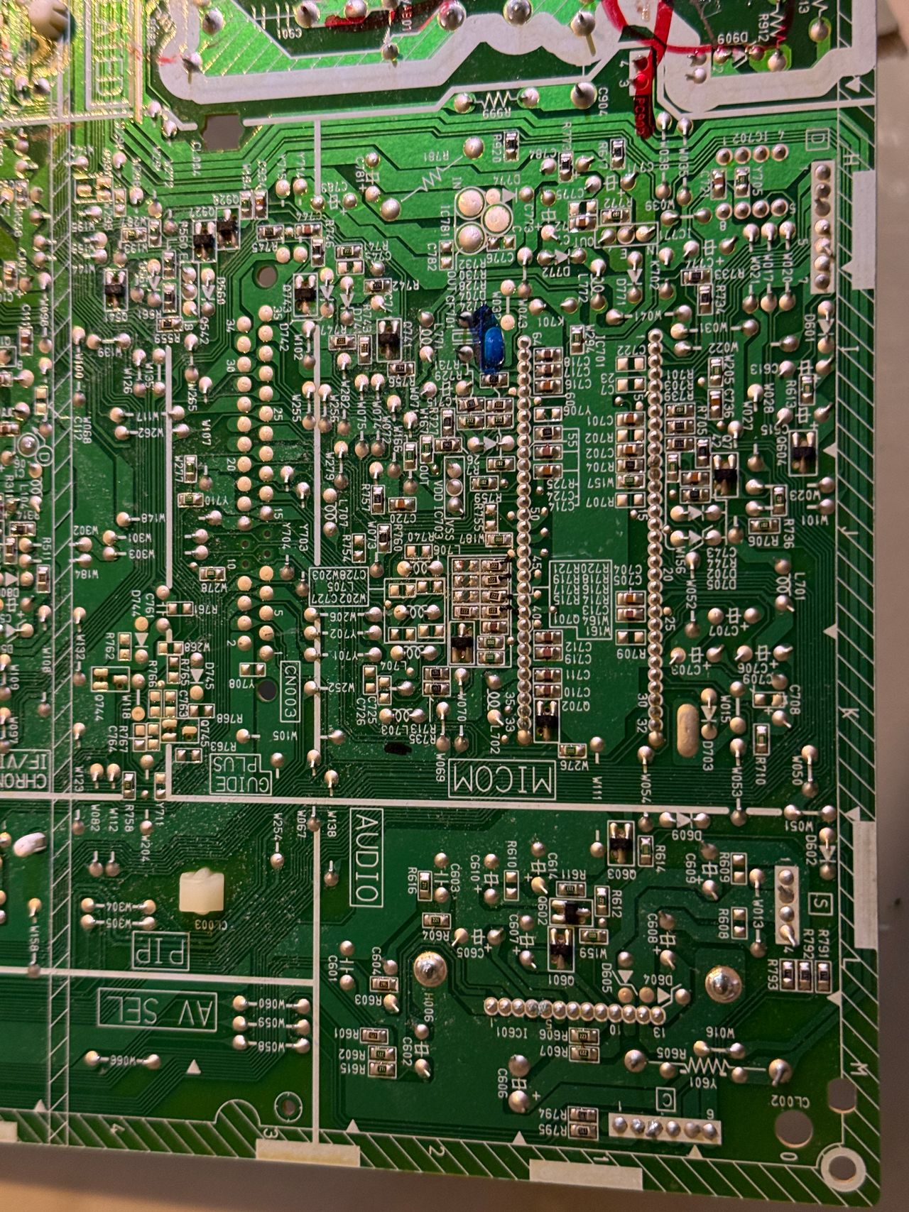
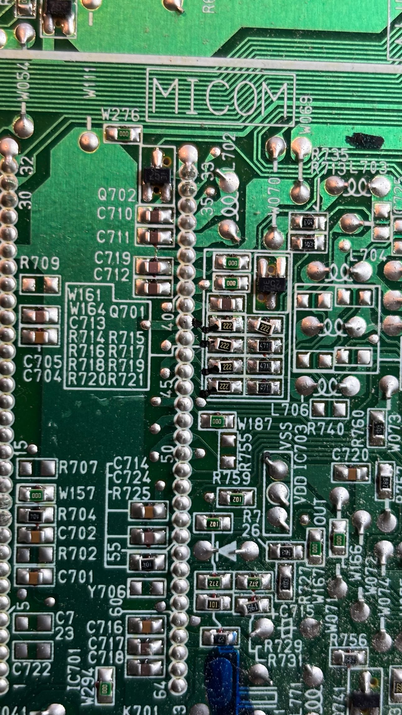
Remove resistors R717, R719, R721
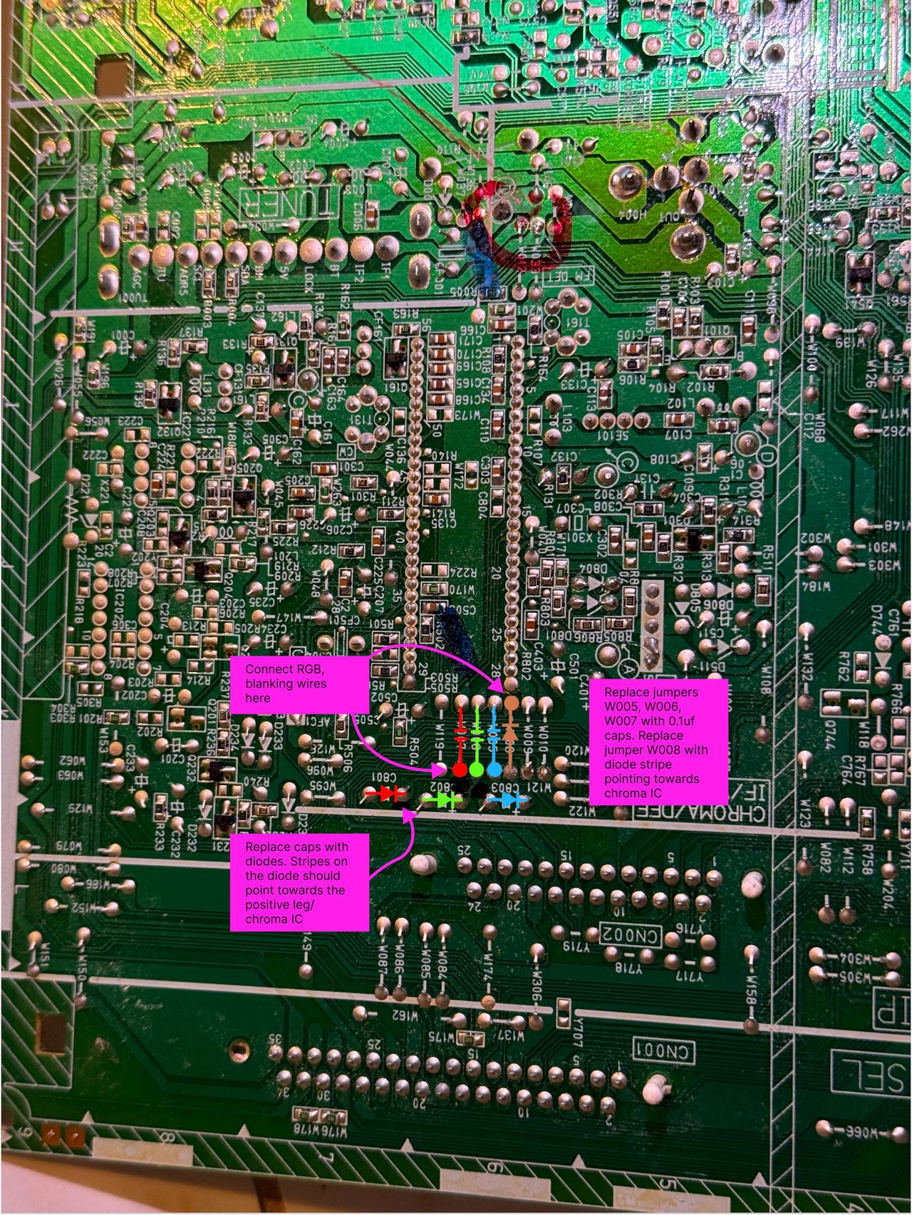
Where to add the capacitors and diodes. You basically remove the jumpers and add the RGB 0.1uf capacitors, diode. Remove the 3 electrolytic capacitors and add diodes. Direction f the diodes matter.
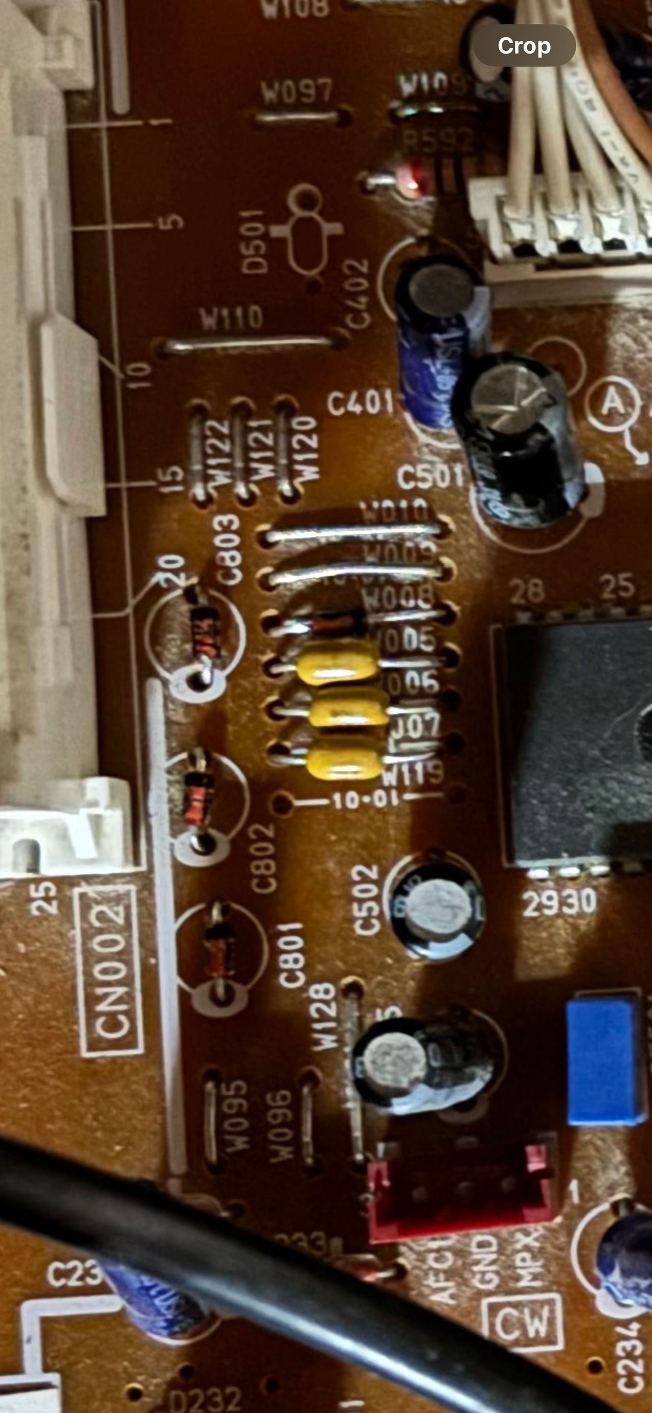
See above for how capacitors and diodes are installed.
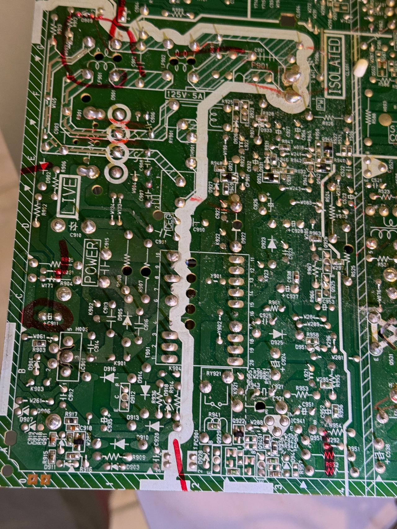
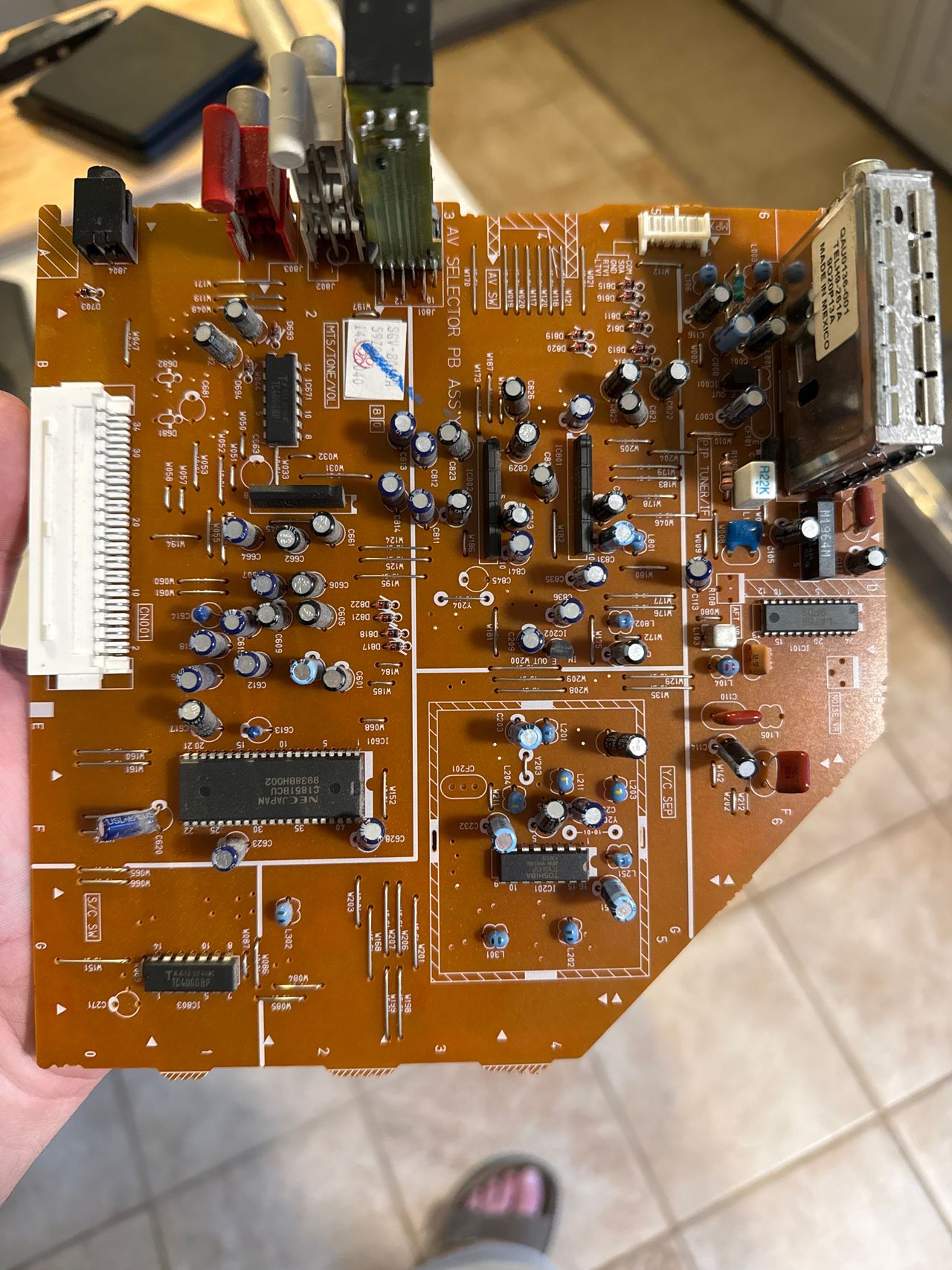
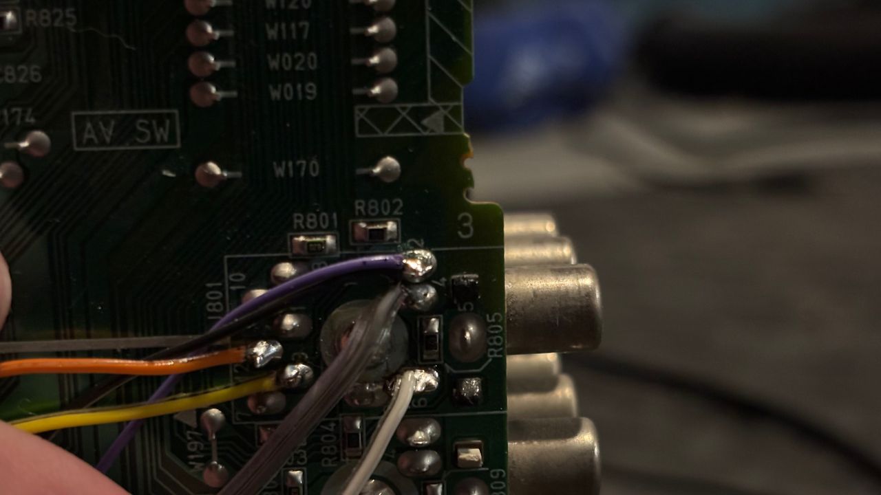
R, G, B, and blanking wire hookup.
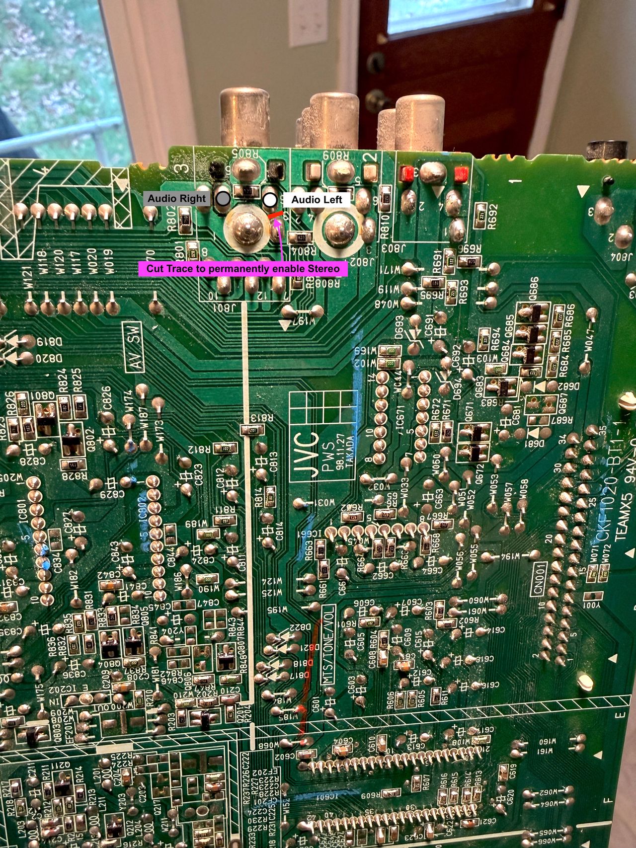
Where to connect audio wires and cut trace to permanently enable stereo.
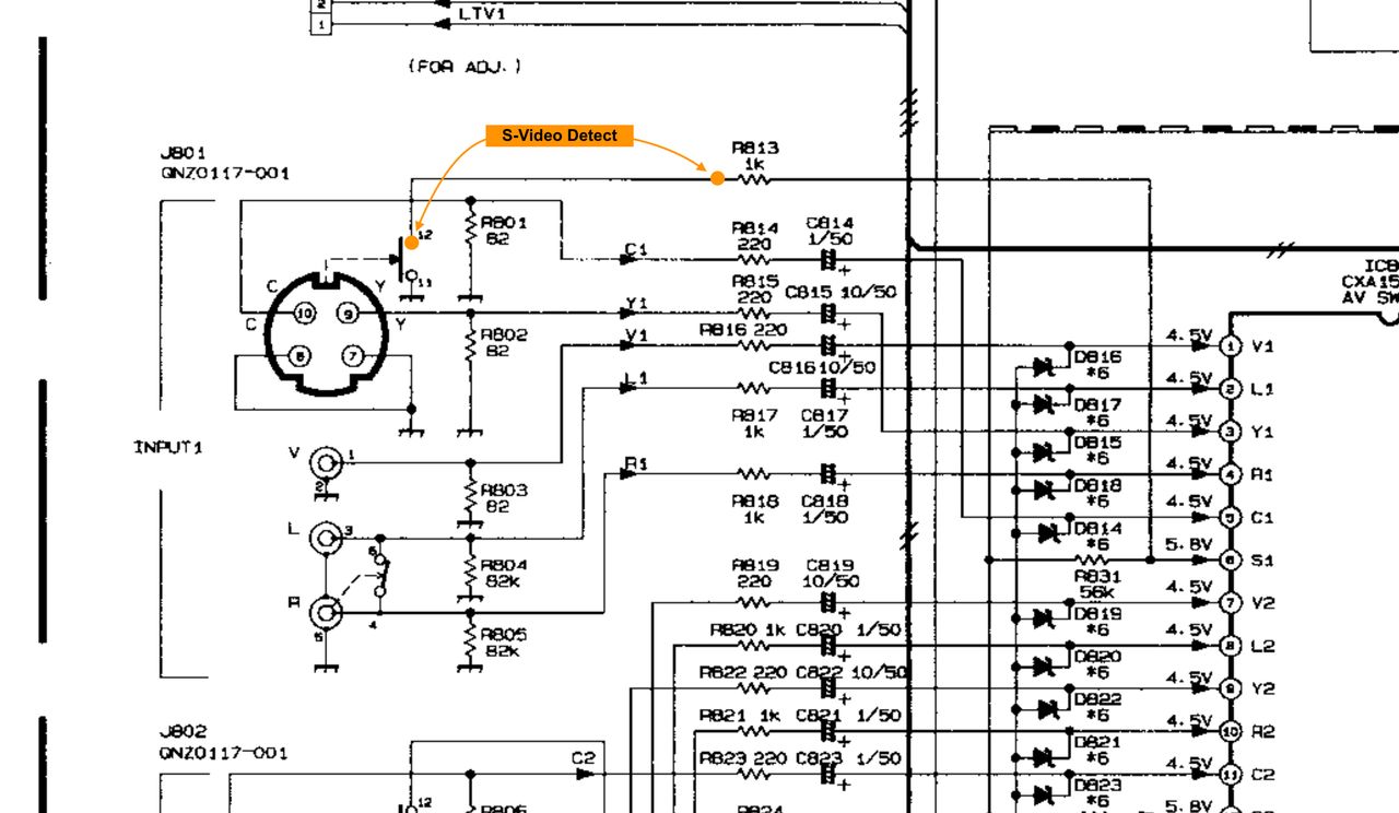
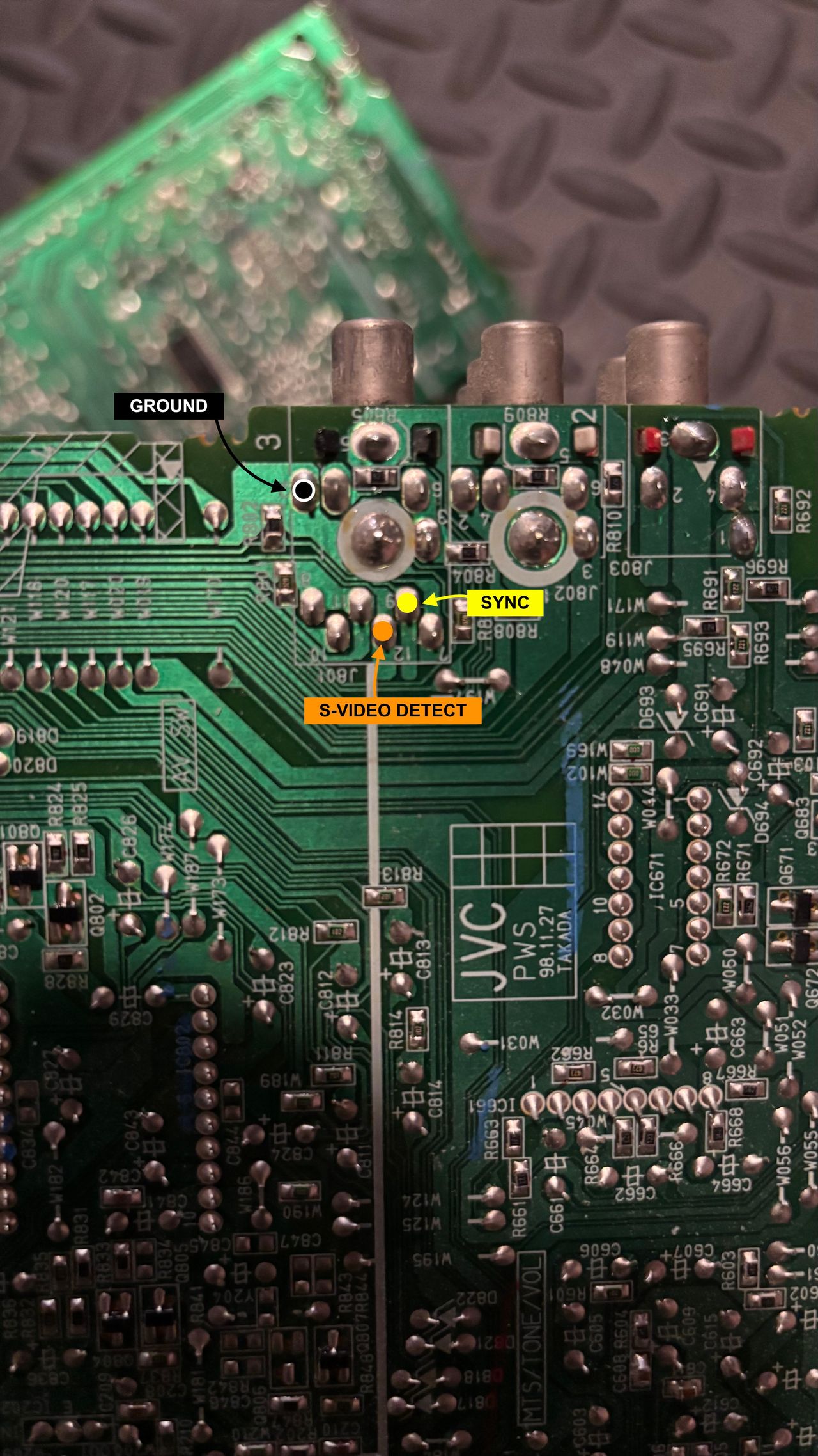
Attach sync and s-video detect. When s-video detect is activated, composite input will be disabled.
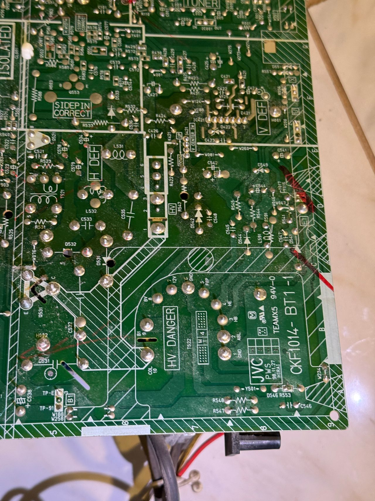
Wiring of R, G, B, s-video detect and sync.
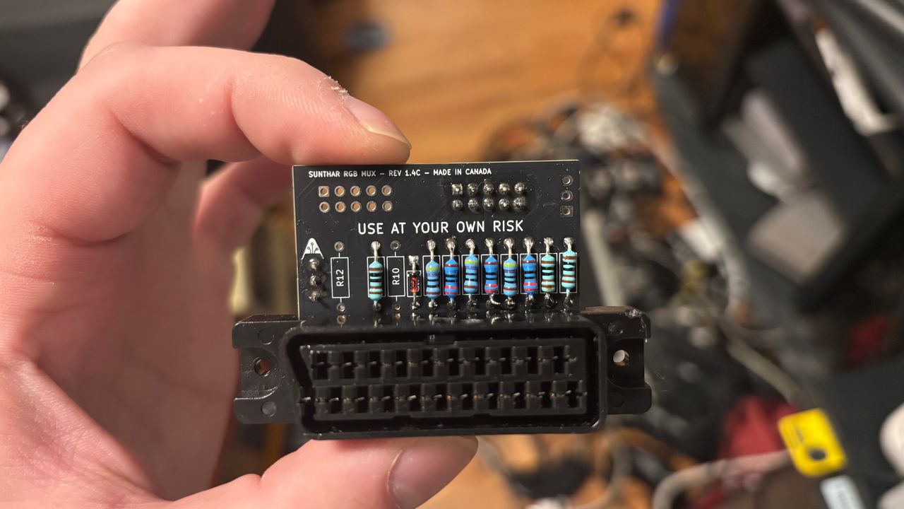
Mux board configuration
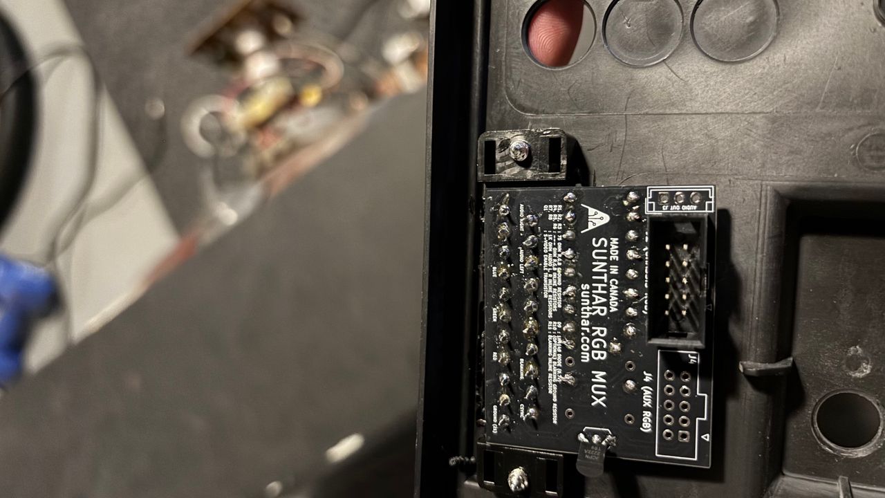
Mux board mounted
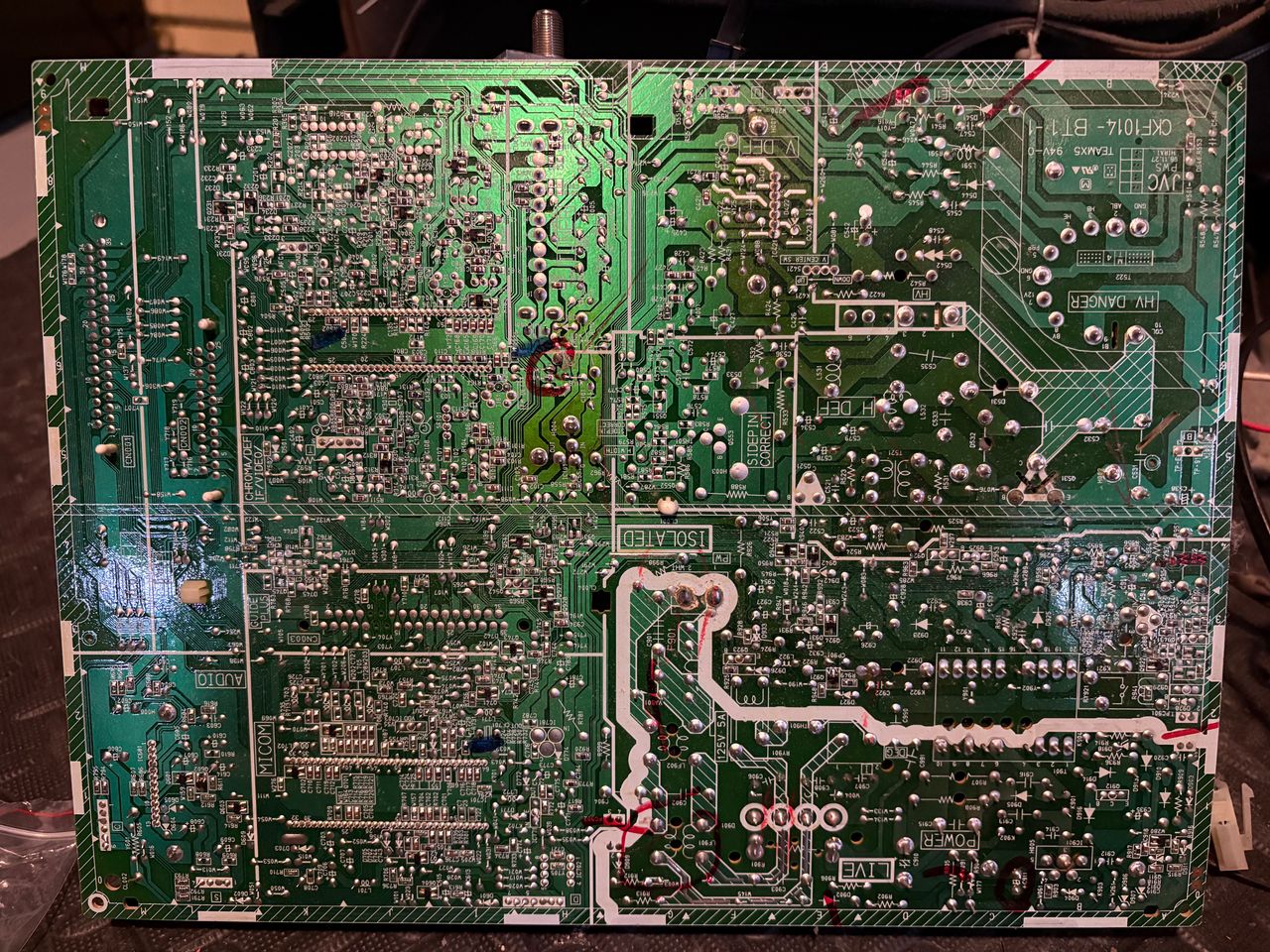
Reference Photos