JVC AV-32D501
JVC AV-32D501 CRT RGB mod
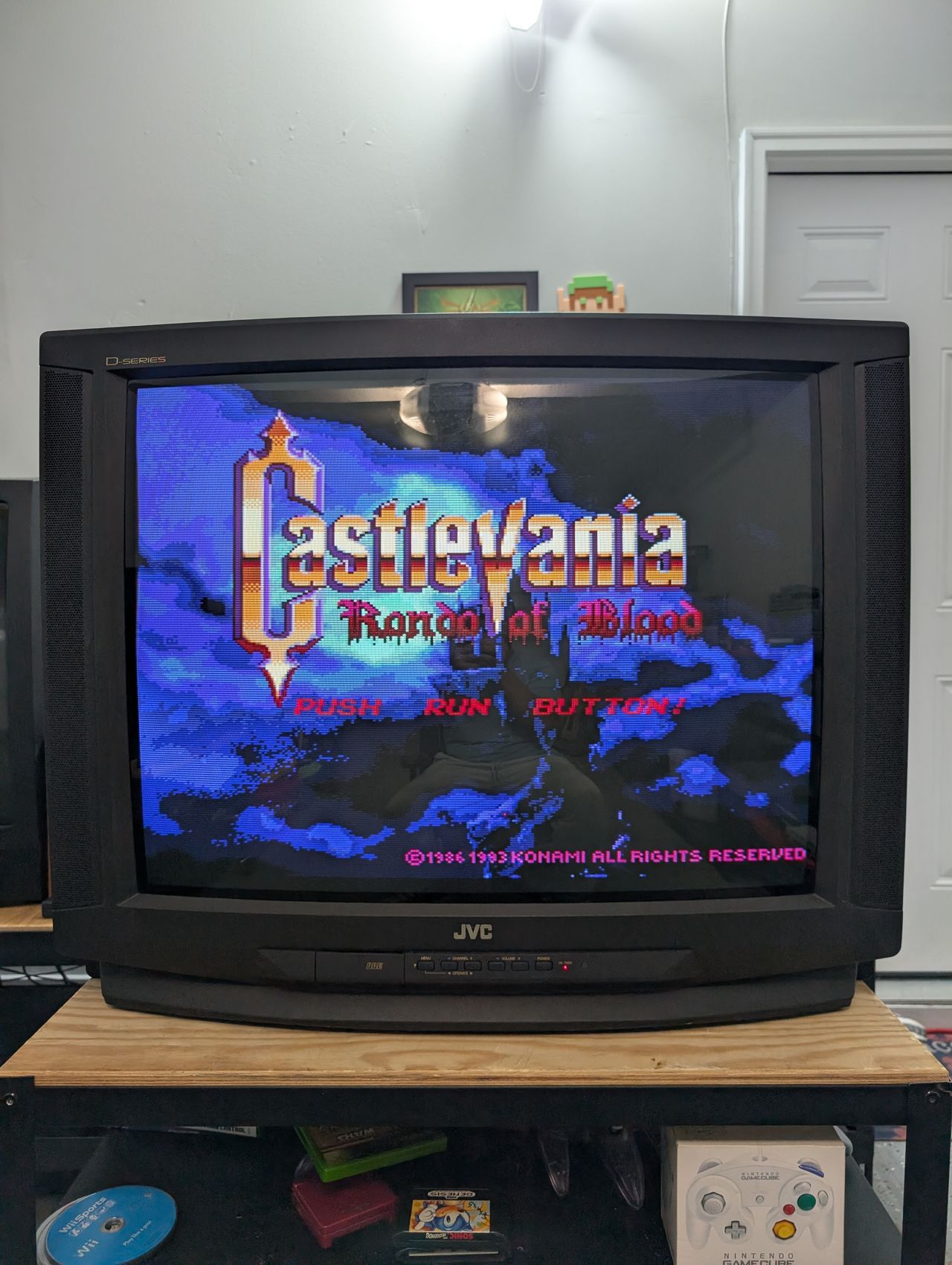
RGB modification of a 32" JVC AV-32D501
View full CRT details and more mod examples →
Contributors
Thank you to everyone who contributed to this guide:
- Michael Lopez — photos and documentation
CRT safety
Caution
You can die doing this! So read carefully! CRT TV is not a toy. Do not open a CRT TV. If you don't have any prior knowledge about handling high voltage devices, this guide is not for you. CRT TV contains high enough voltage (20,000+ V) and current to be deadly, even when it is turned off.
Plan of attack
Service manuals
Specs
- Year: 2000
- Format: NTSC
- Chassis: GR2
- Jungle Chip: JVC JCC1007A
- OSD Chip: Matsushita MN1876478JD
- Screen Size: 32"
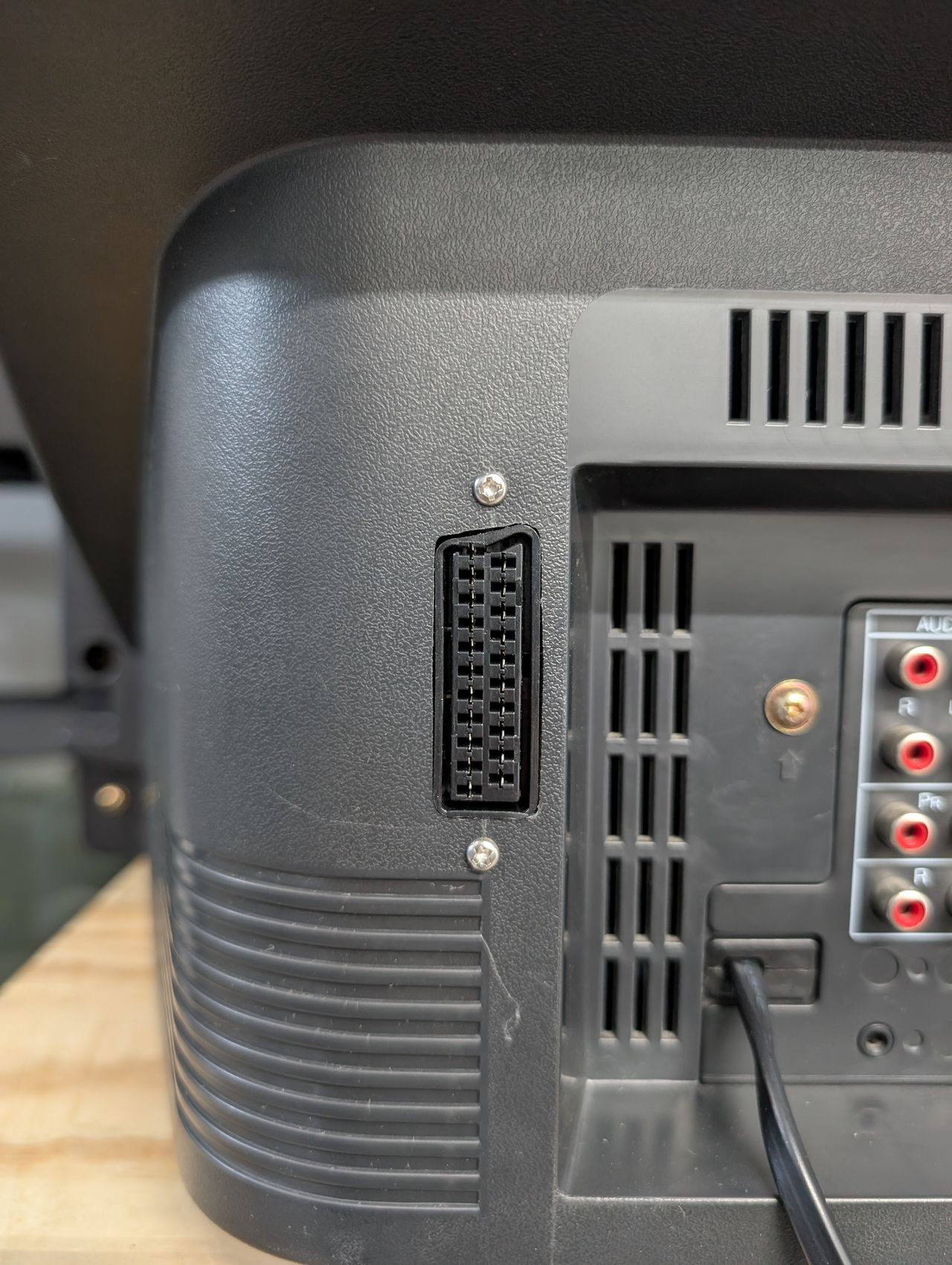
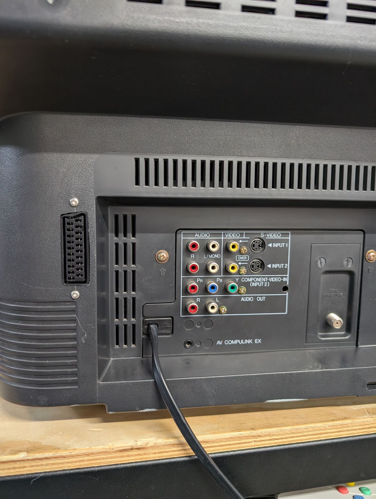
- Inputs: Composite, S-Video, RF, Component YPbPr
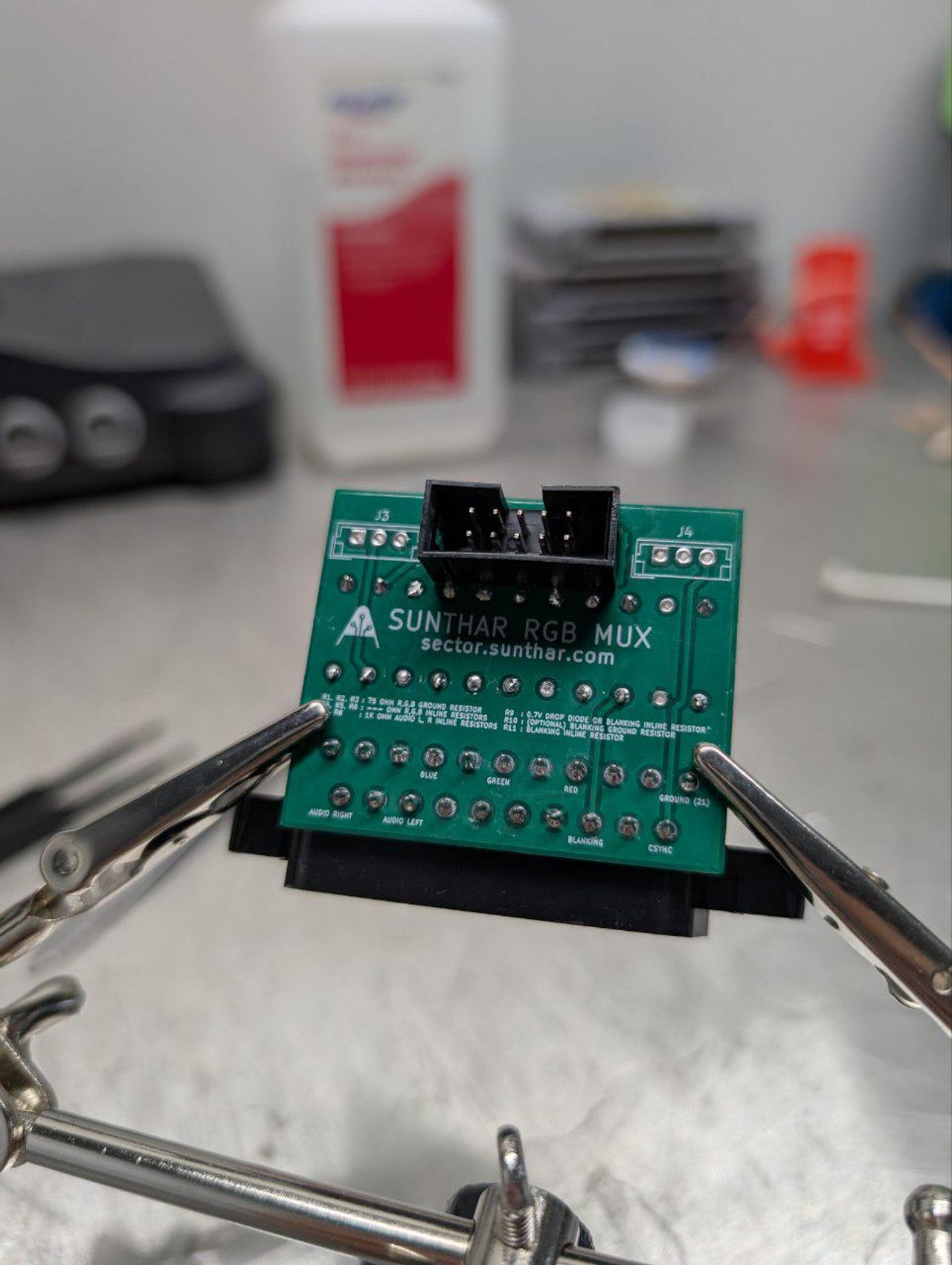
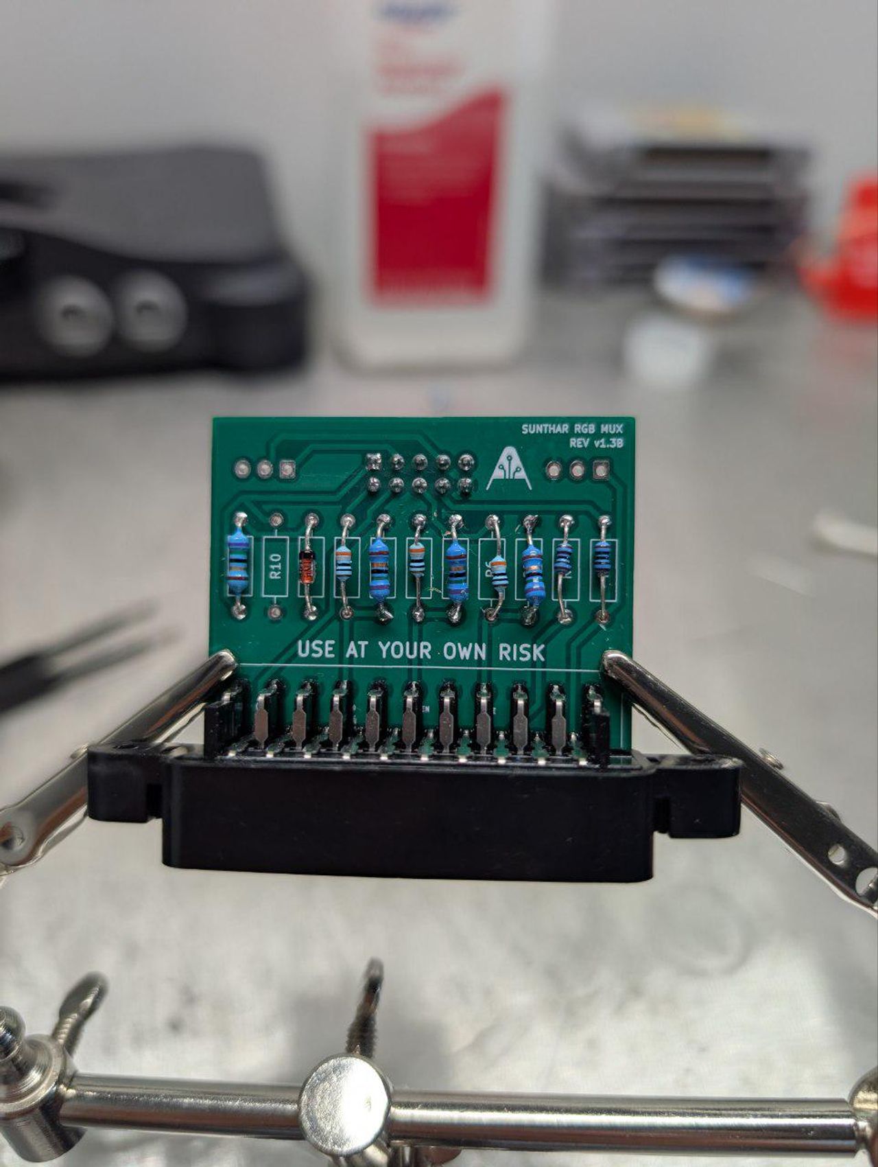
RGB mux diagram
This mod uses the RGB mux board. This is optional, but will make your mod easier and stable. You can also create the circuit presented in the schematics above without the board. Please also checkout the mux calculator to play with your own values.
| Component | Value |
|---|---|
| RGB/OSD inline resistor (chassis) | 2.2kΩ |
| Removed RGB/OSD resistor (chassis) | 330Ω |
| RGB inline diode method (chassis) | Yes |
| 0.1μF caps replaced (chassis) | Yes |
| RGB termination (R1, R2, R3) | 75Ω |
| RGB inline (R4, R5, R6) | 390Ω |
| Audio LR (R7, R8) | 1kΩ |
| Diode (R9) | 1N4148 |
| Blanking Ground Resistor (R10) | open |
| Blanking Resistor (R11) | 1kΩ |
Performing the mod
Detailed mod instructions to be added.
Pictures
Photos by Michael Lopez's Sector
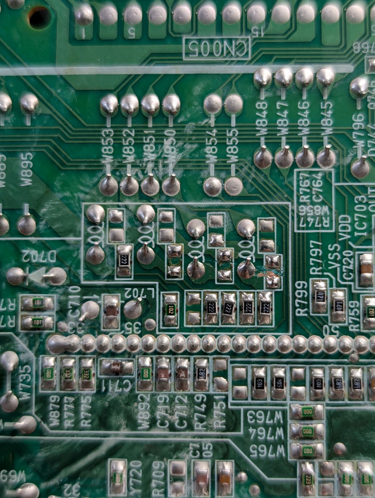
Resistors removed
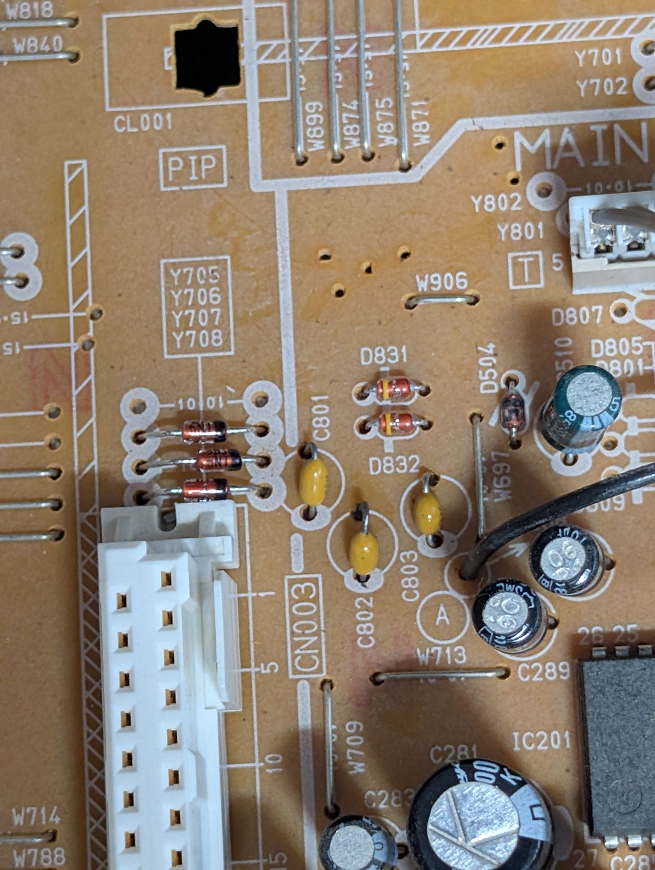
Diodes and capacitors installed. Pay attention to the direction.
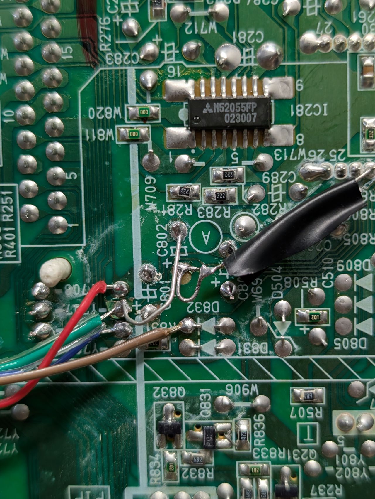
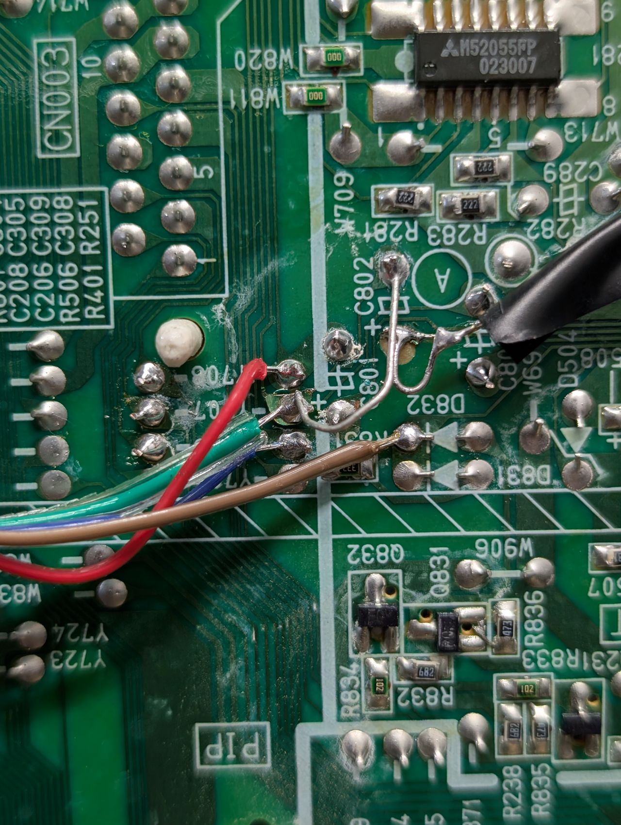
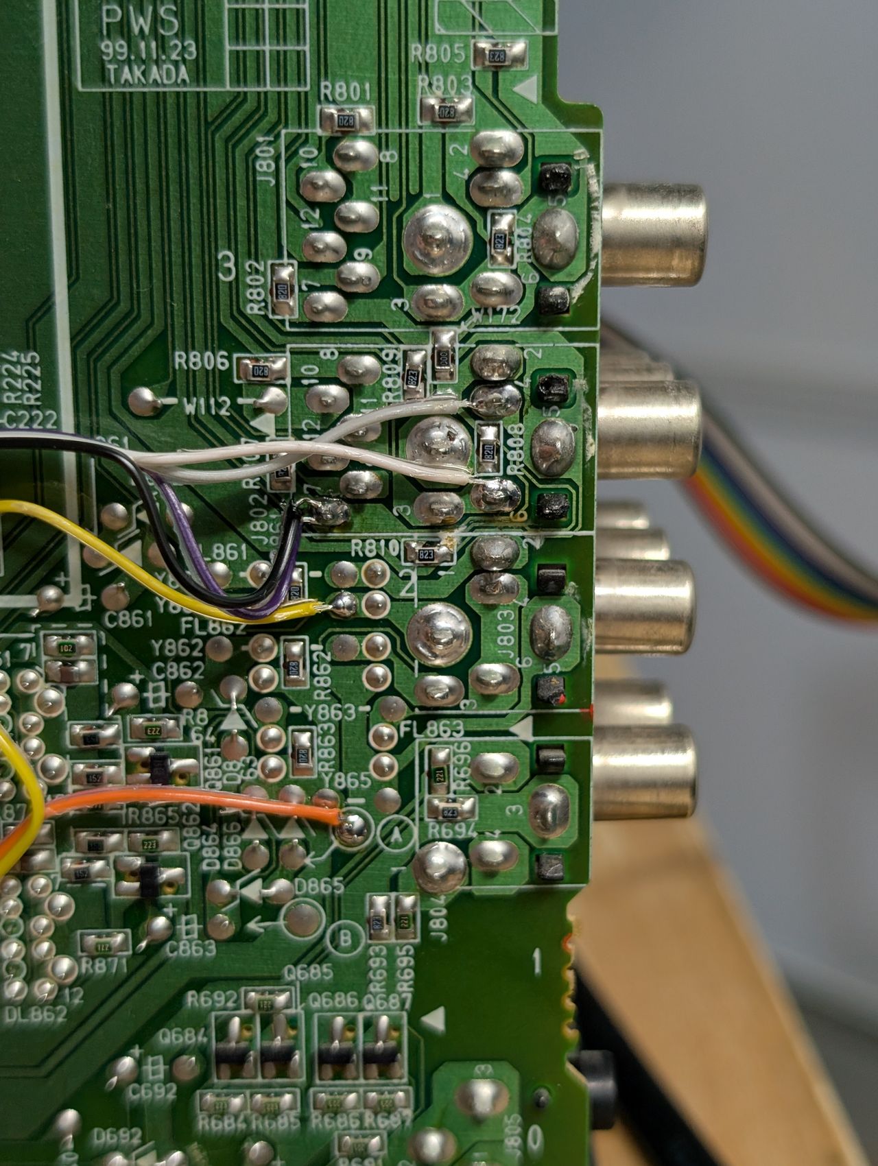
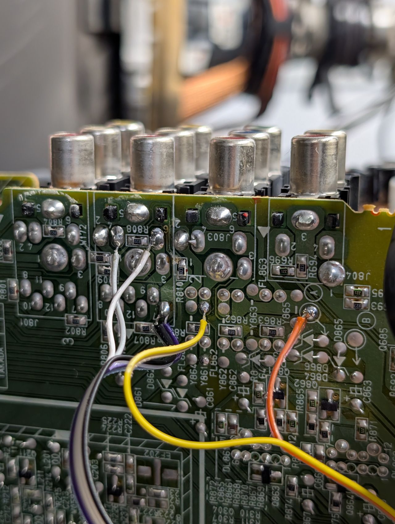
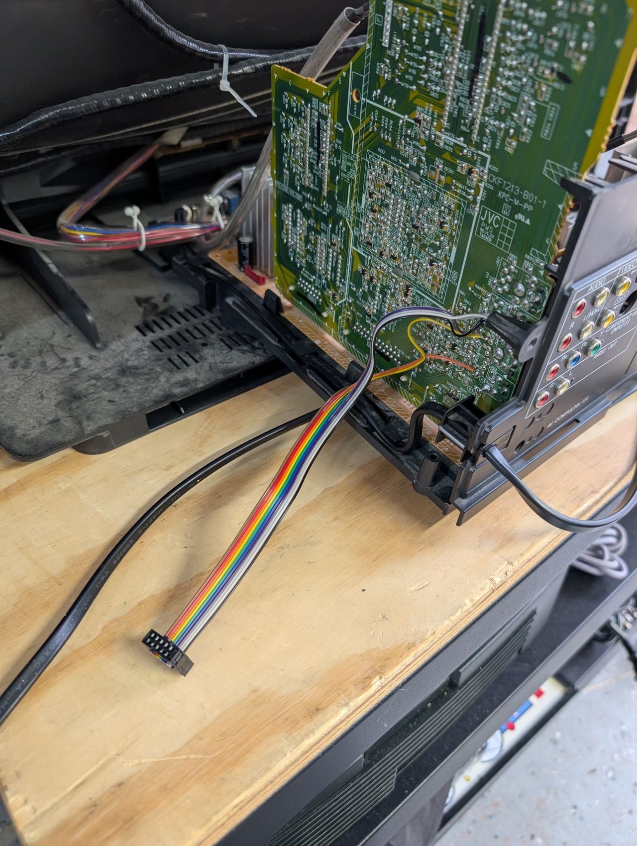
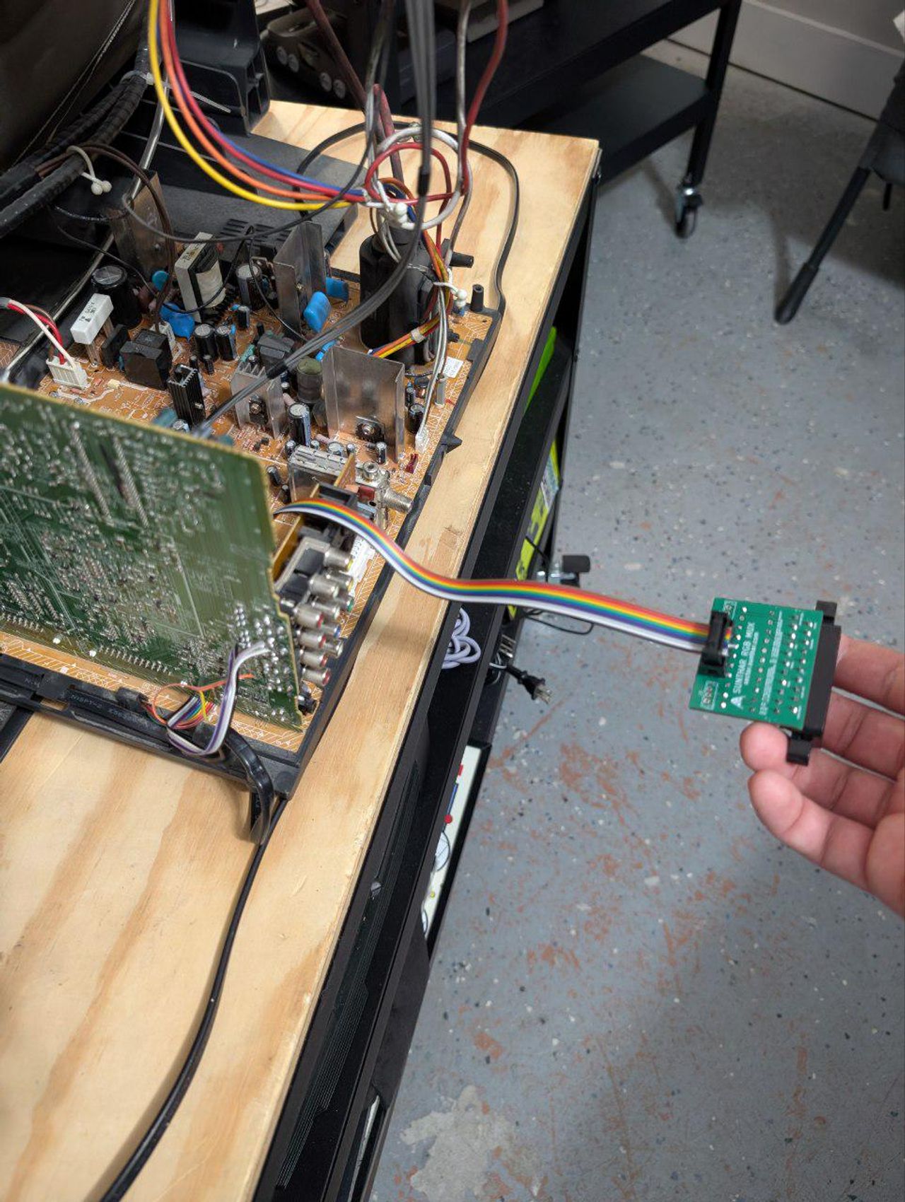
Sync, audio and ground wires
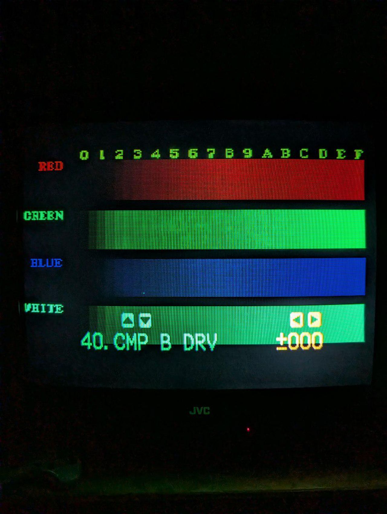
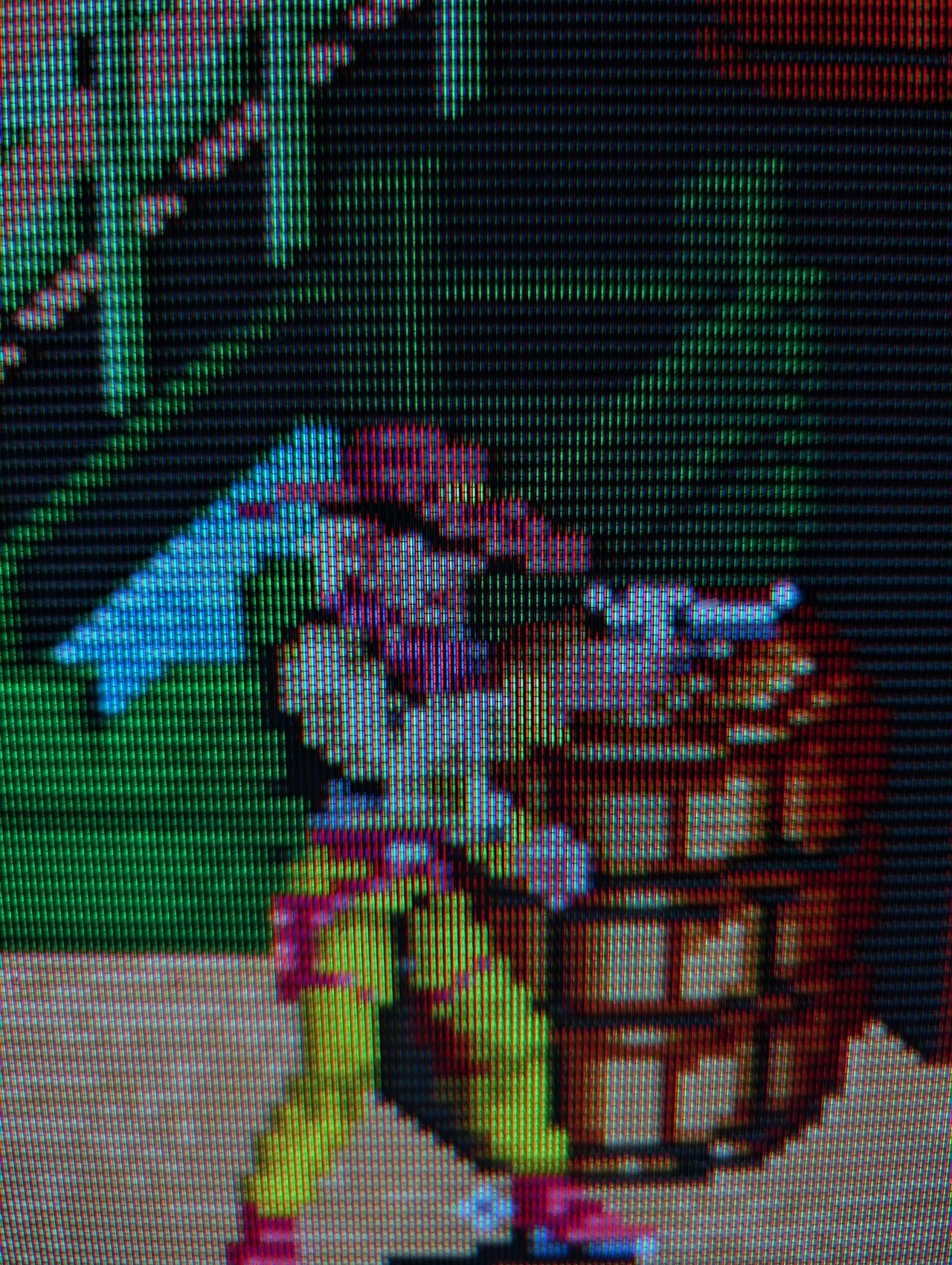
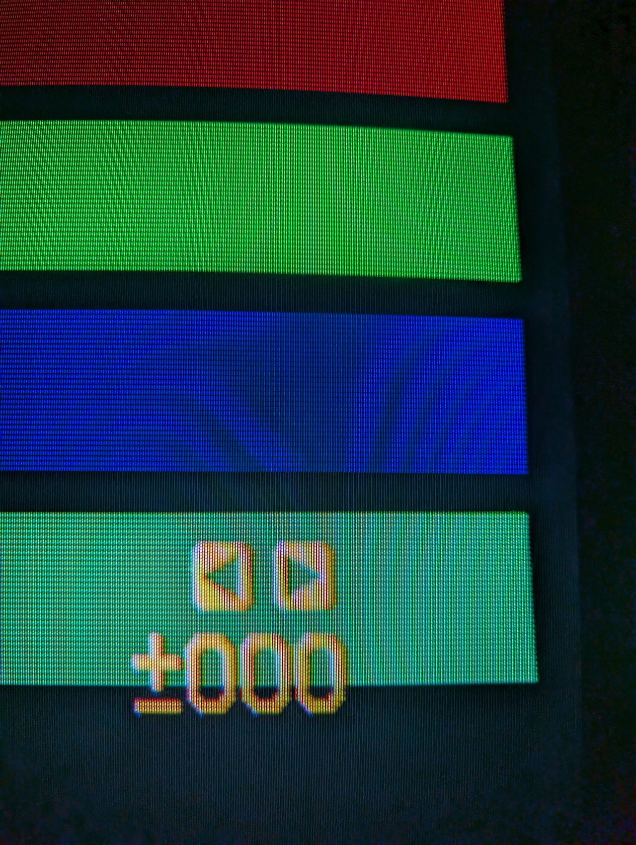
After the RGB mod a very bad green tint issue was noticed.
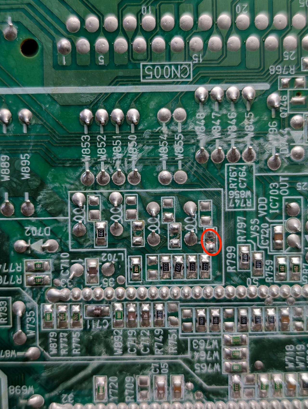
Resistor pad had some reside.
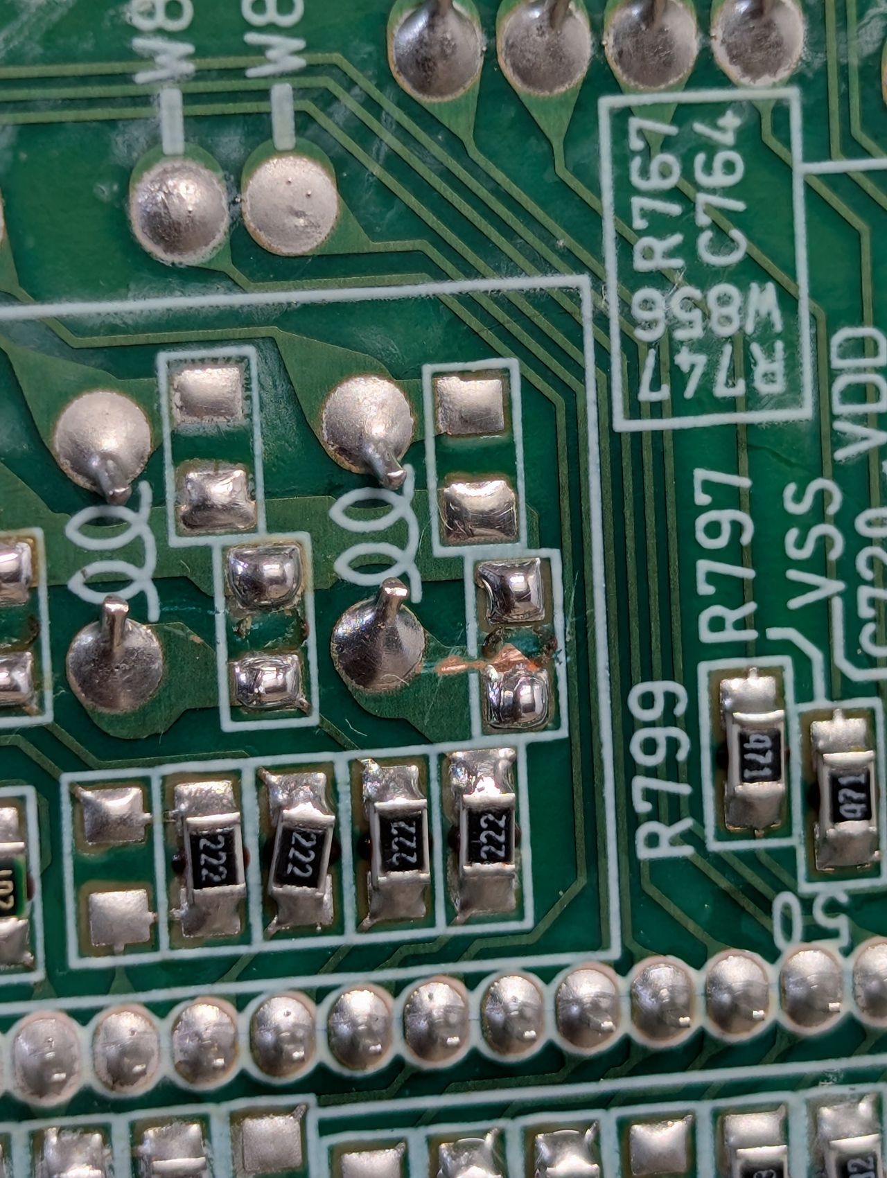
This resistor pad was cleaned, but the tint issue was still there.
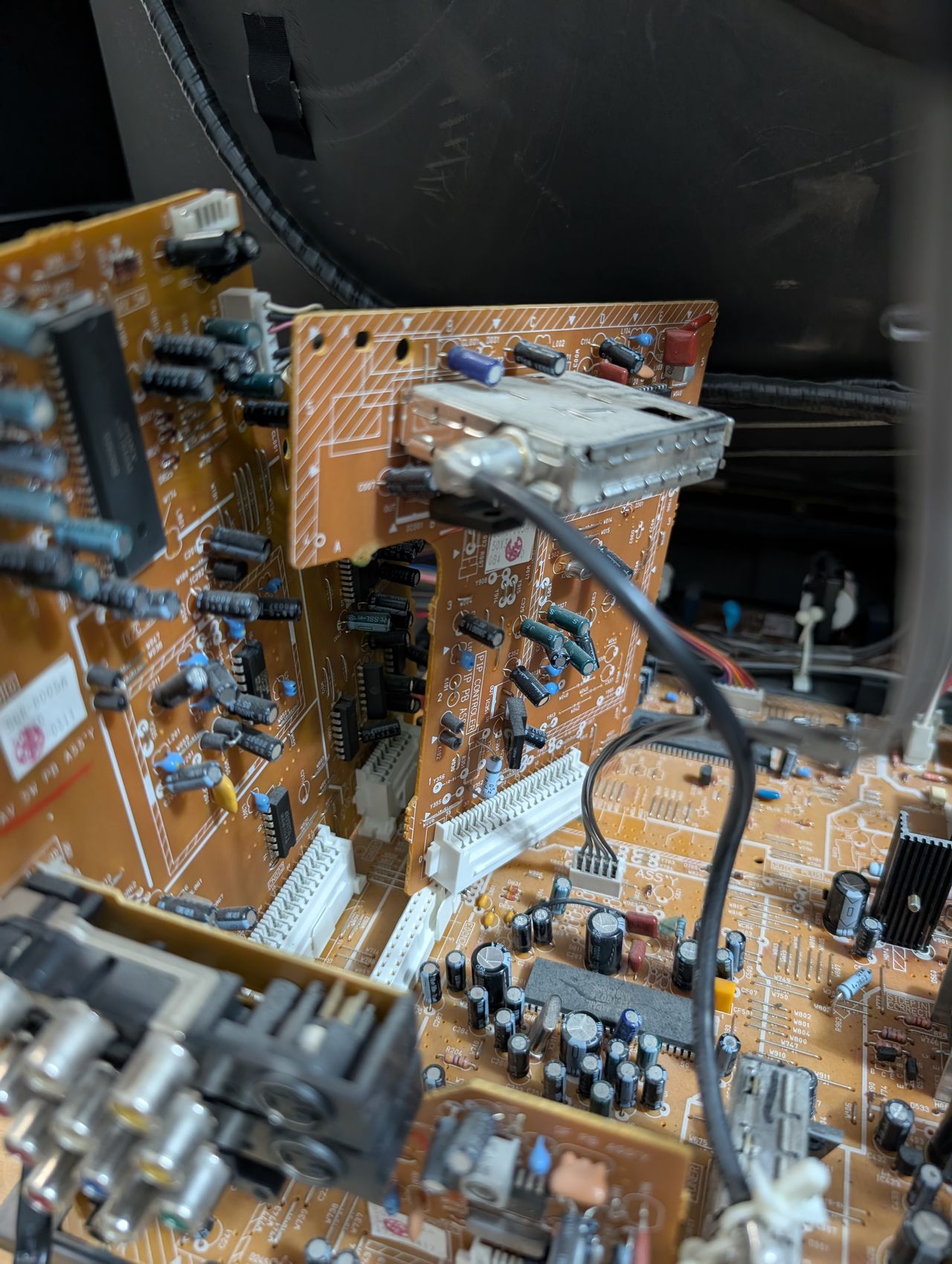
What fixed the issue was removing the picture-in-picture board.
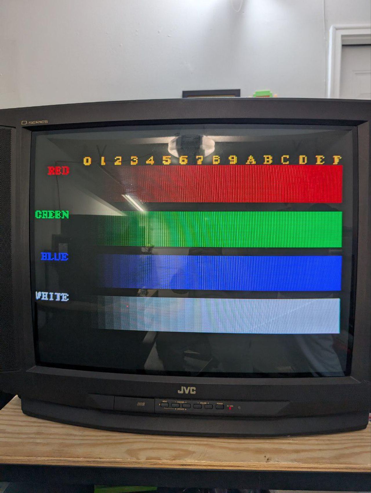
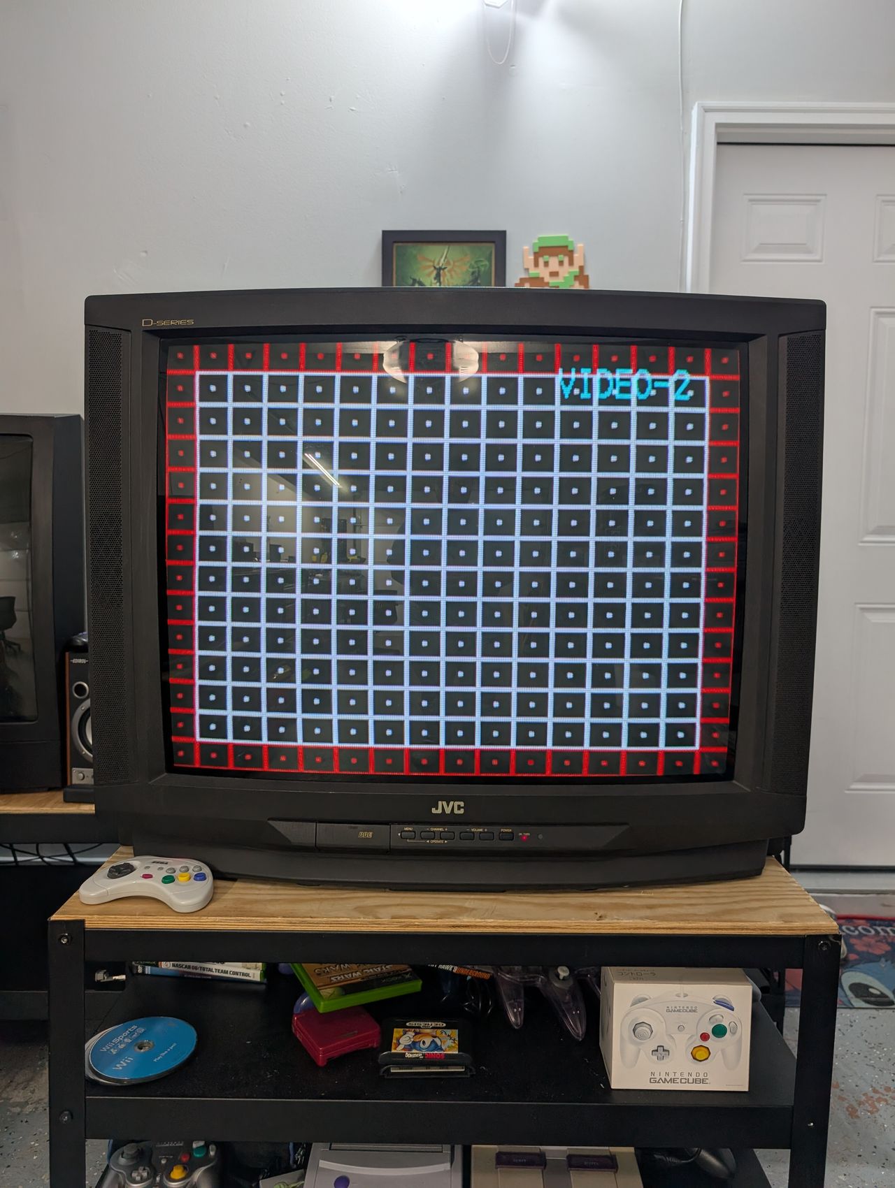
After fixing the issue. Red color was later tweaked in the service menu by adjusting the CUTOFF value.