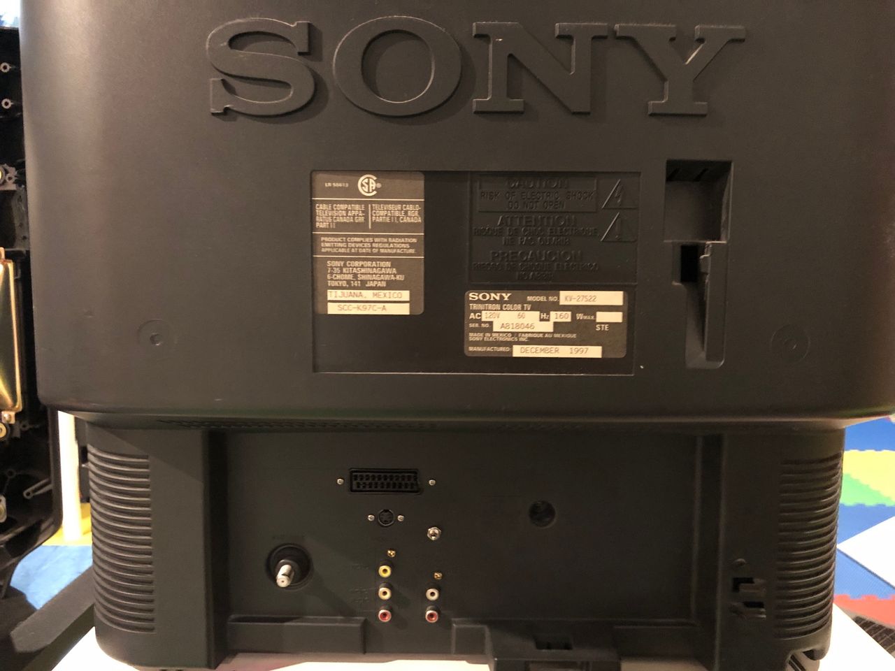
Sony (AA-2) KV-27S22
Sony (AA-2) KV-27S22 CRT RGB mod
This AA-2D chassis based curved Trinitron was introduced in 1997. Designed as the entry-level option, it lack s-video input shipped only with a single composite input. Despite that, the TV is highly mod-friendly: the disabled S-Video circuit can be reinstated, and the hardware supports modifications for RGB and component signals.
Additional input functions can be activated through the service menu.

View full CRT details and more mod examples →
Contributors
Thank you to everyone who contributed to this guide:
- Sunthar — author, RGB mod information + pics
CRT safety
Caution
You can die doing this! So read carefully! CRT TV is not a toy. Do not open a CRT TV. If you don't have any prior knowledge about handling high voltage devices, this guide is not for you. CRT TV contains high enough voltage (20,000+ V) and current to be deadly, even when it is turned off.
Plan of attack
Service manuals
Specs
- Year: 1997
- Format: NTSC
- Chassis: AA-2
- Tube: Sony Trinitron A68KZJ50X
- Jungle Chip: Sony CXA2025AS
- OSD Chip: CXP8564D-004S
- Screen Size: 27"
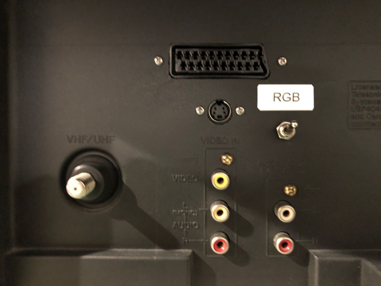
- Inputs: Composite, RF
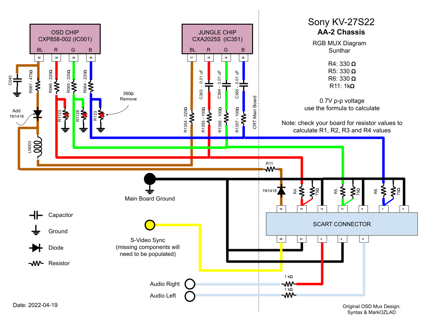
RGB mux diagram
This mod uses the RGB mux board. This is optional, but will make your mod easier and stable. You can also create the circuit presented in the schematics above without the board. Please also checkout the mux calculator to play with your own values.
| Component | Value |
|---|---|
| RGB/OSD inline resistor (chassis) | 2.2kΩ |
| Removed RGB/OSD resistor (chassis) | 390Ω |
| RGB inline diode method (chassis) | No |
| RGB termination (R1, R2, R3) | 75Ω |
| RGB inline (R4, R5, R6) | 330Ω |
| Audio LR (R7, R8) | 1kΩ |
| Diode (R9) | 1N4148 |
| Blanking Ground Resistor (R10) | 330Ω |
| Blanking Resistor (R11) | 470Ω |
Performing the mod
This set does not have an S-Video. Therefore sync can be applied to the rebuilt s-video luma path.
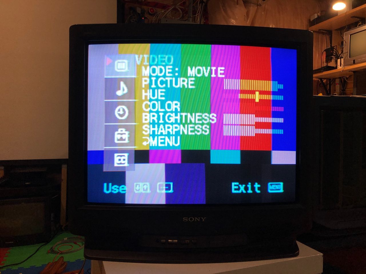
Getting into the service menu
- Turn the set on and then put into standby
- Press the
Display,5,VOL +buttons in sequence - Turn on the CRT and you should be in service mode
- Use buttons "1" and "4" on the remote control to navigate the service menu
- Use buttons "3" and "6" to adjust the selected data
Enabling second video input
This step is necessary if you want to do an S-Video mod, or use luma for RGB sync.
ID-1 in the Service Menu configures the audio/video input/output configuration.
We can see from the Sony ID codes document, ID-1 is 1 for KV-27S22 and 21 for KV-27S26. So I tried changing from 1 to 21. Voila! Video-2 input was now enabled.
Manufacturers of TV sets often choose to utilize ID based configuration bits for enabling or disabling specific inputs and outputs. This is due to the cost-effective nature of software-based feature management. In the case of Sony sets, typically ID-1 is used for this purpose.
Failed scenarios
- Tried setting ID-1 to
25didn't enable Video 2. Likely because the CRT I had was a Canadian version. Setting ID-1 to21worked.
13" KV-13M42 has mono sound and a single AV input. However, a second video input can be enabled in the service menu by changing the value of ID-1 to 3
S-Video mod
The Sony KV-27S22 was not originally equipped with an S-Video connector, so the initial task is to establish functionality for this input. Incorporating an S-Video input is always desirable and fortunately, the process of adding one to this particular model is relatively straightforward, as long as one has access to clear instructions on how to proceed.
If you want to use luma for sync, this step is necessary for this particular set. For sets that already have an S-Video input, you can just feed the sync signal to luma input directly.
Adding S-Video
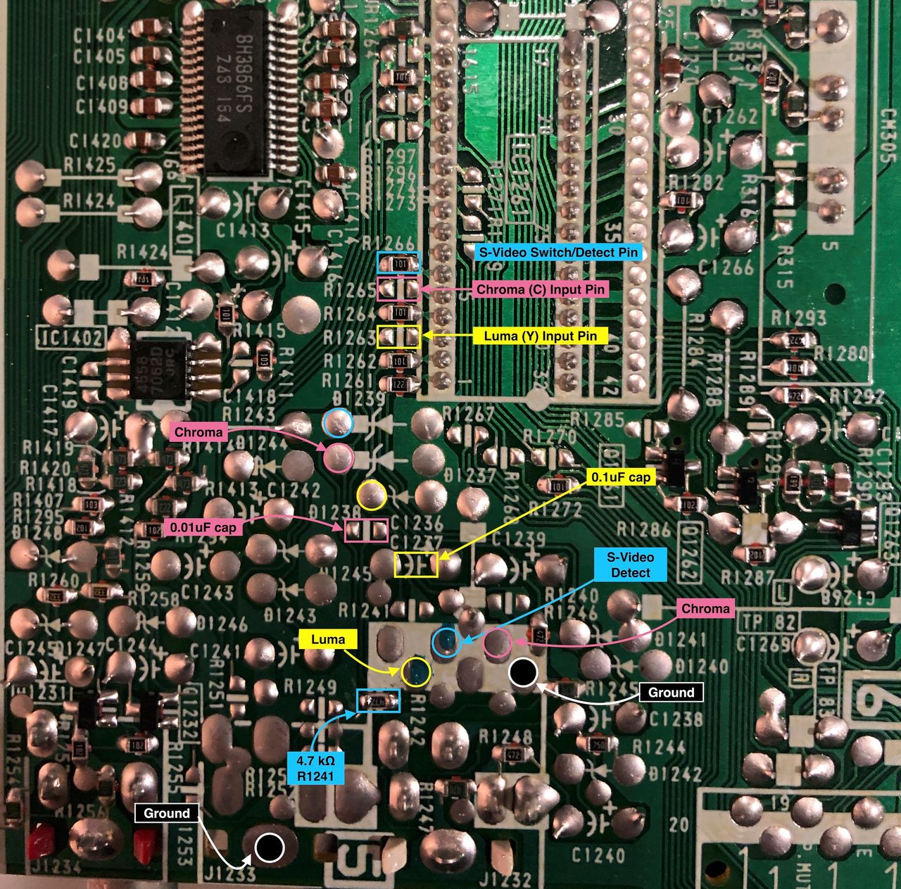
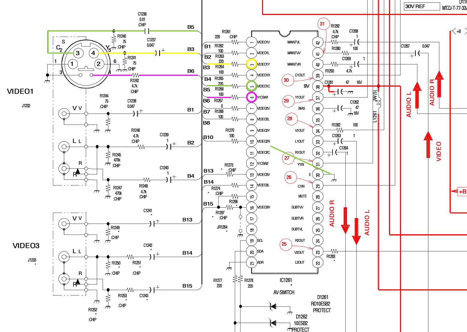
In order to activate S-Video on the KV-27S22, I had to add several components. There are two options: populate the existing traces with the missing components, or fill in the missing components and connect them directly to the IC1261 AV Switch.
If you choose the latter method, you would then supply:
- Luma to
Video 1 Y(pin 3) - Chroma to
Video 1 C(pin 5) - Ground switch to
Y/C SW1(pin 6)
WhenY/C SW1is grounded through a 4.7kohm resistor, S-Video is enabled.
If you want to preserve the composite input (on Video 1), then routing this through a switch is essential. You can also connect the sync signal for RGB to S-Video luma. This way there is minimal shift.
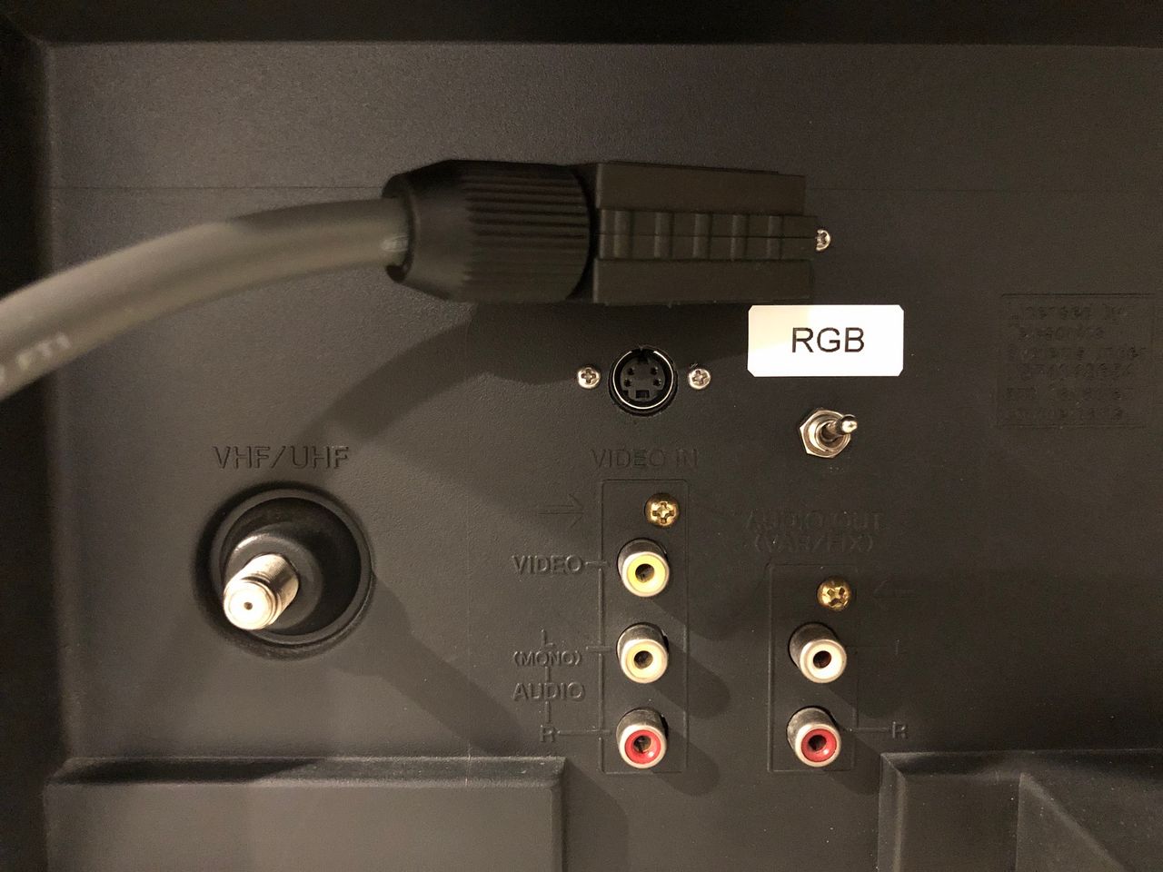
Below diagram shows how the female S-Video connector should be wired. The S-Video connector I used doesn't have a detect pin. Essentially detect pin gets grounded when an S-Video cable is inserted. This signals the AV switch to enable Y/C inputs instead of the Video 1 input. 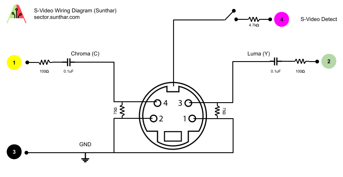
Often times it is confusing which pin is Chroma and Luma. See below picture for details. 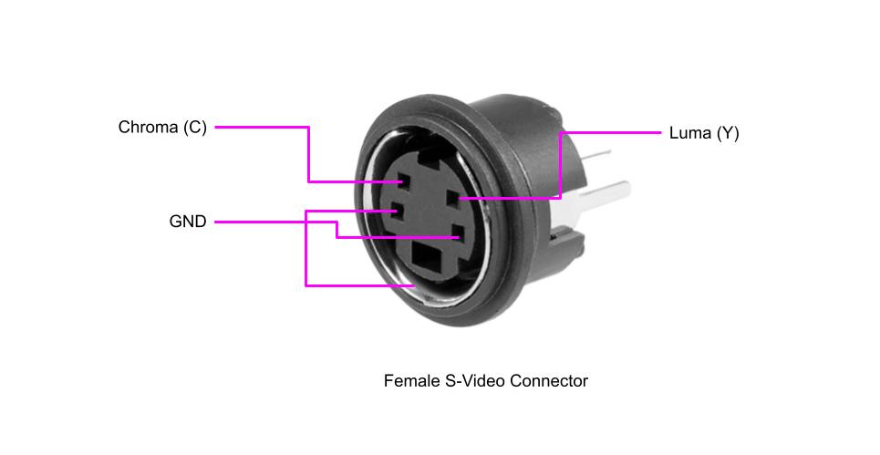
Below picture shows how S-Video chroma and luma are connected on the solder side of the chassis. There are several options here on how you can connect both the chroma and luma to the A/V switch. You can populate some or all of the components on the chassis itself. I chose to do a hybrid. Pictures below explain it. 
Below pictures demonstrate how to put the S-Video mod plan in action. I shorted one of the pins. Added a 100ohm resistor to the other as I was able to source one. 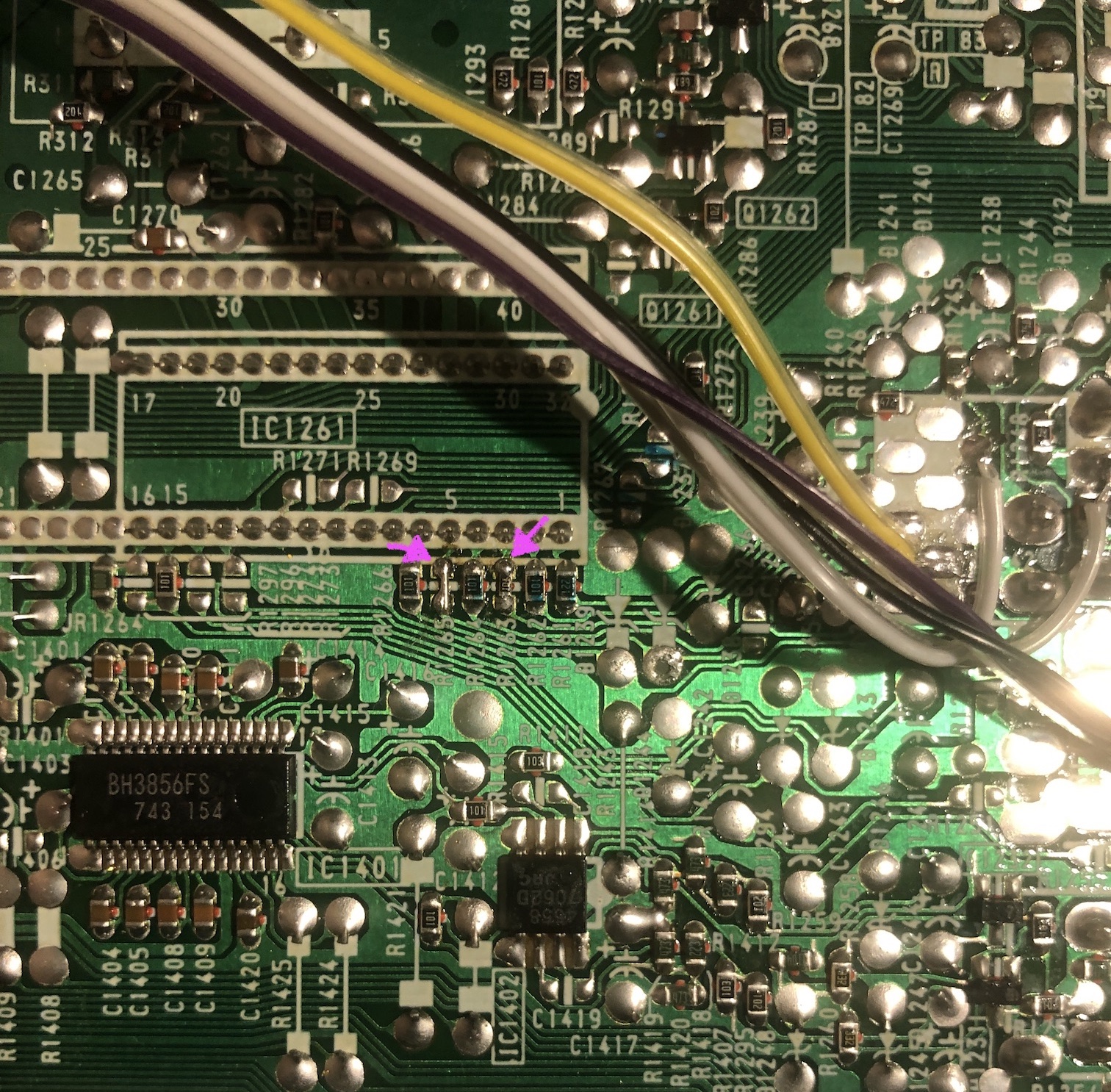
0.1uF ceramic cap was used on the luma input line 
Convenient via on the chassis was available to attach the chroma signal. It goes through a 0.01uF ceramic capacitor and a resistor before reaching the AV switch. 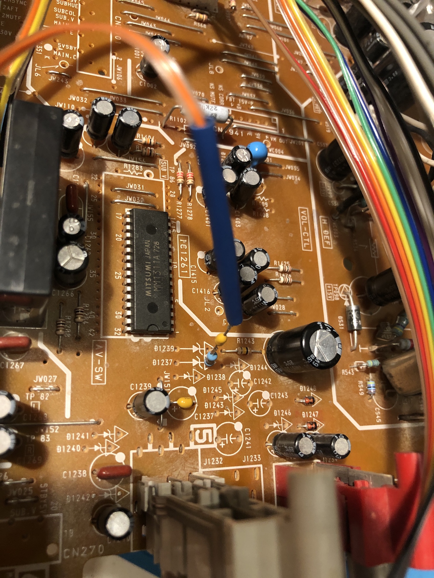
While all of this may seem confusing, my actions simply involve finalizing the S-Video circuit that was previously described.
By feeding only the Luma signal, a flawless monochrome image is displayed. This is one way to confirm part of your S-Video circuitry is working. Enabling RGB input only requires modifying the CRT to accept the Luma input. Chroma circuitry is only necessary if you intend to utilize an S-Video input. 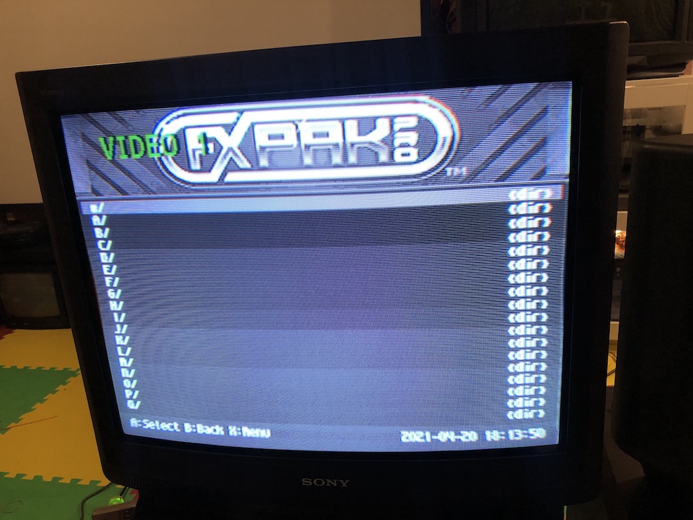
The outcome is highly satisfying, as S-Video delivers a considerably impressive image quality. 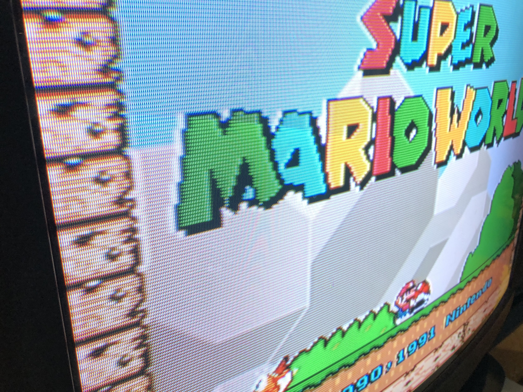
Please take note that a few of the images presented earlier were captured prior to making adjustments to the sharpness and convergence of the CRT, which might have resulted in some blurring. But, at this point we have confirmed the S-Video mod is working as intended.
Failed scenarios
- Connected the Chroma and Luma in reverse order. Got a black and white picture that was out of sync
RGB mod
RGB modding is the most exciting part of the mod. Below you will find instructions on how to do this on a AA-2 chassis. These instructions should also work for AA-2D chassis as well.
RGB mux diagram
If you are building your own circuit, this diagram should help. The diagram is for KV-27S22, it will also work for other AA-2 chassis based Sony CRTs. This diagram is very similar to AA-2D chassis.
Step 1: Remove the following components
Remove the following resistors
- R1123
- R1128
- R133
Inject R, G, B at the below locations
- R1123 (Red)
- R1128 (Green)
- R133 (Blue)
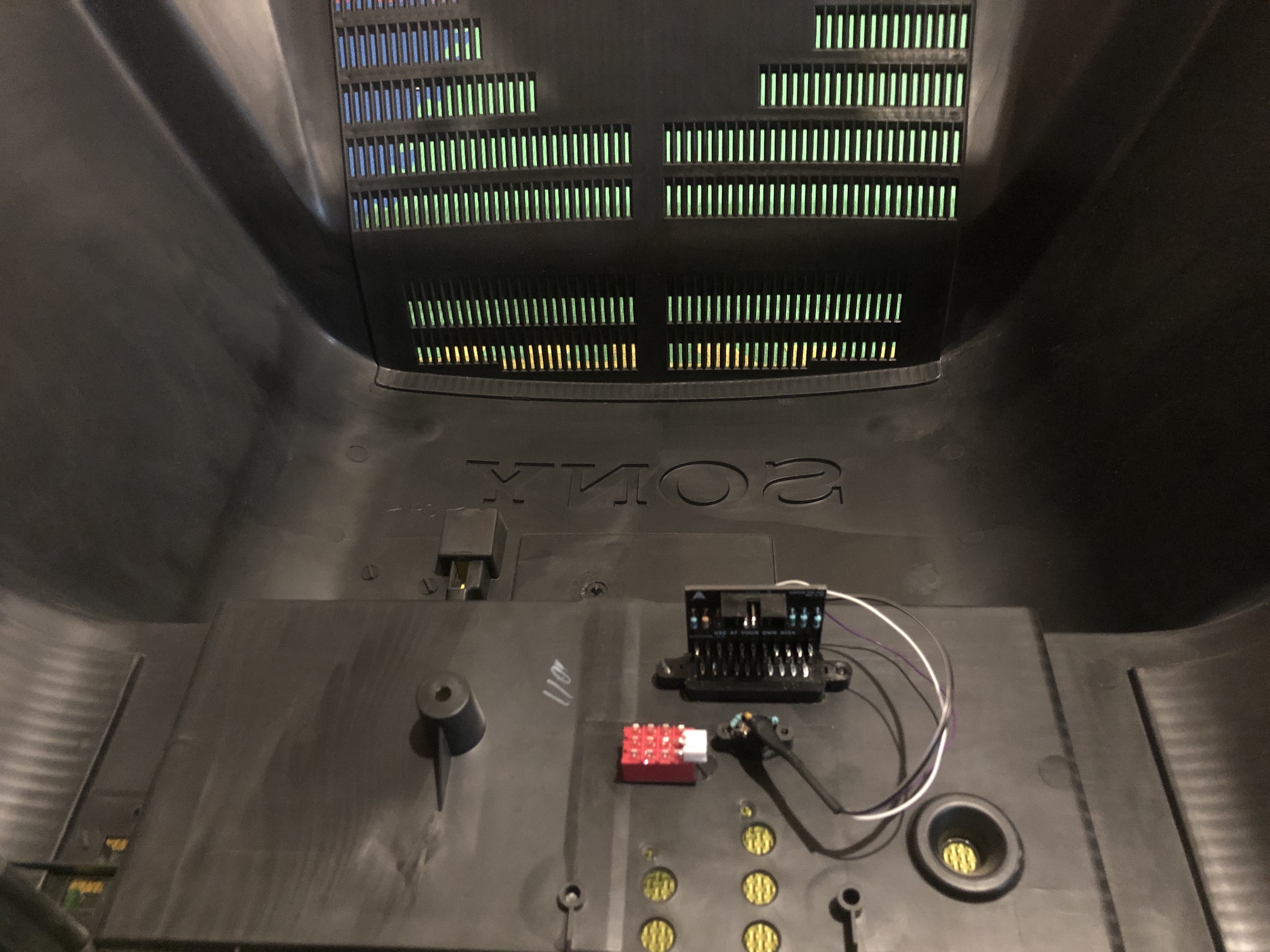
Below picture shows the resistors that were removed and where we are going to connect the R, G, B and blanking wires. 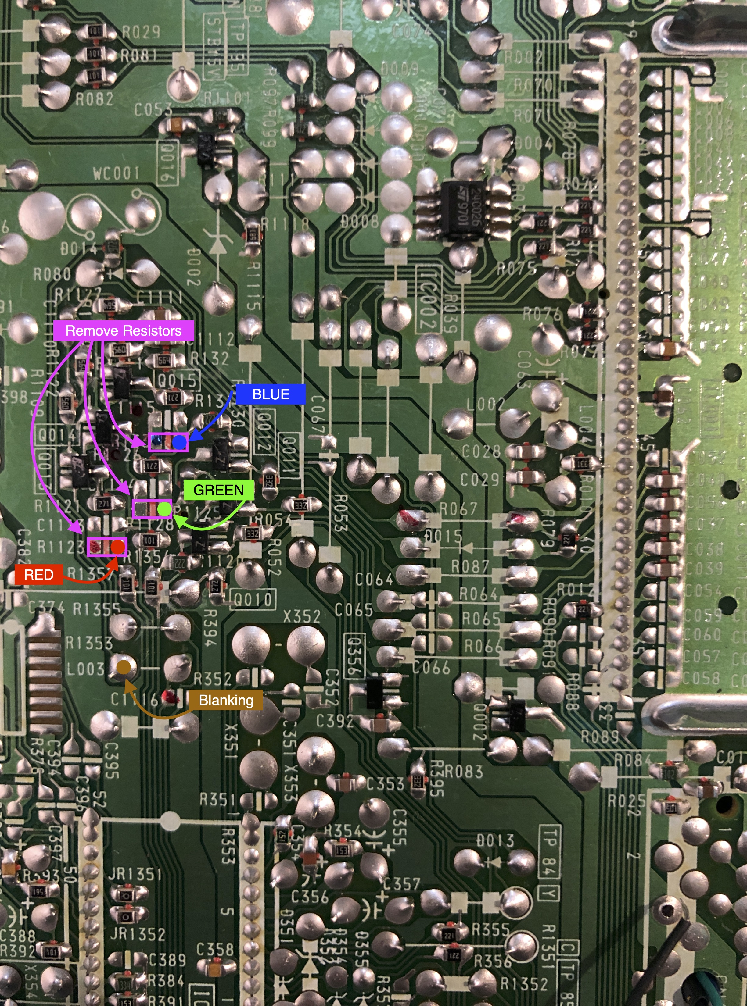
Step 2: Add a diode to blanking
Blanking diode added. Helps reduce interference. This mod was performed without shielded cables internally and absolutely no interference was noticed.
![]()
Step 3: Connect RGB and blanking wires
- Blanking = brown wire
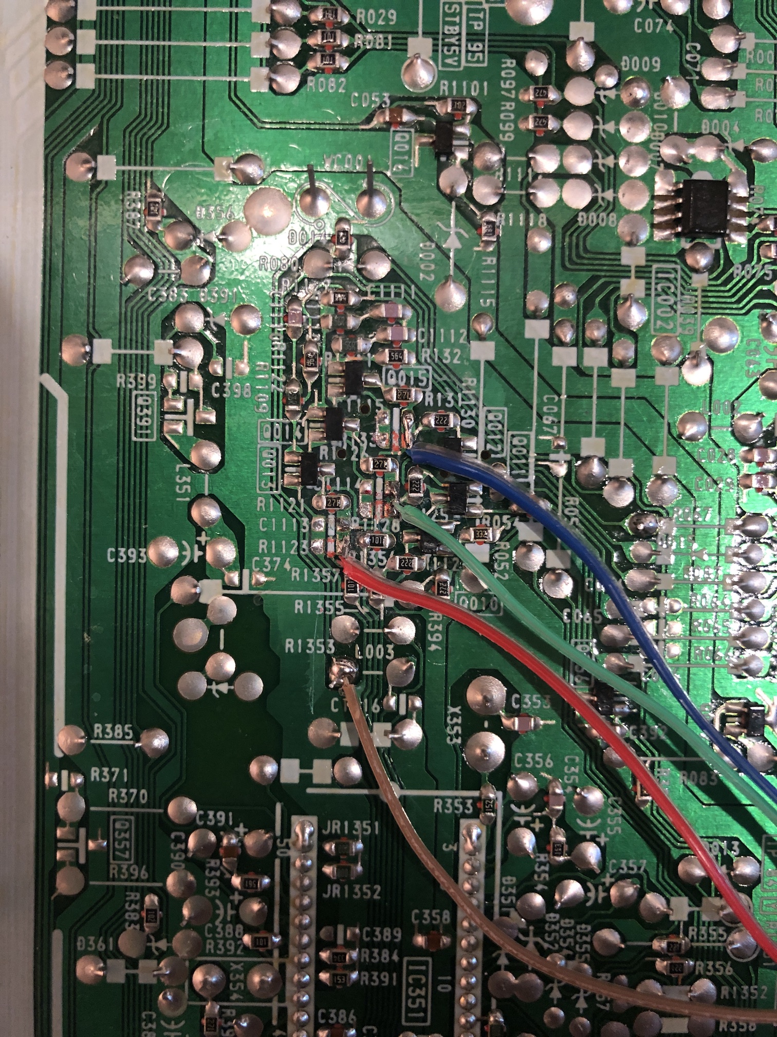
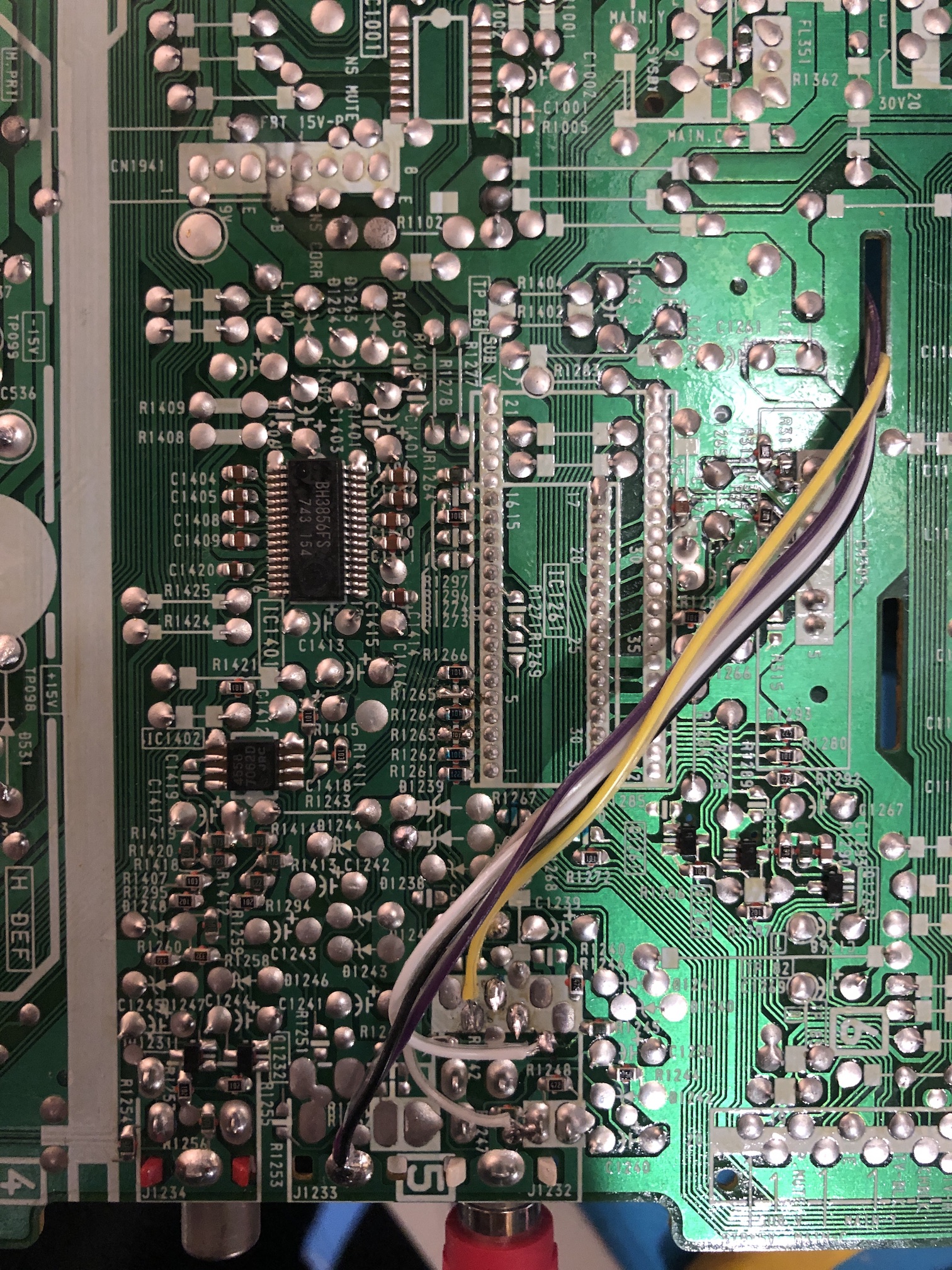
Step 4: Connect audio and sync wires
- Ground = Purple/Black wires
- Yellow = Sync
- White = Left Audio
- Grey = Right Audio
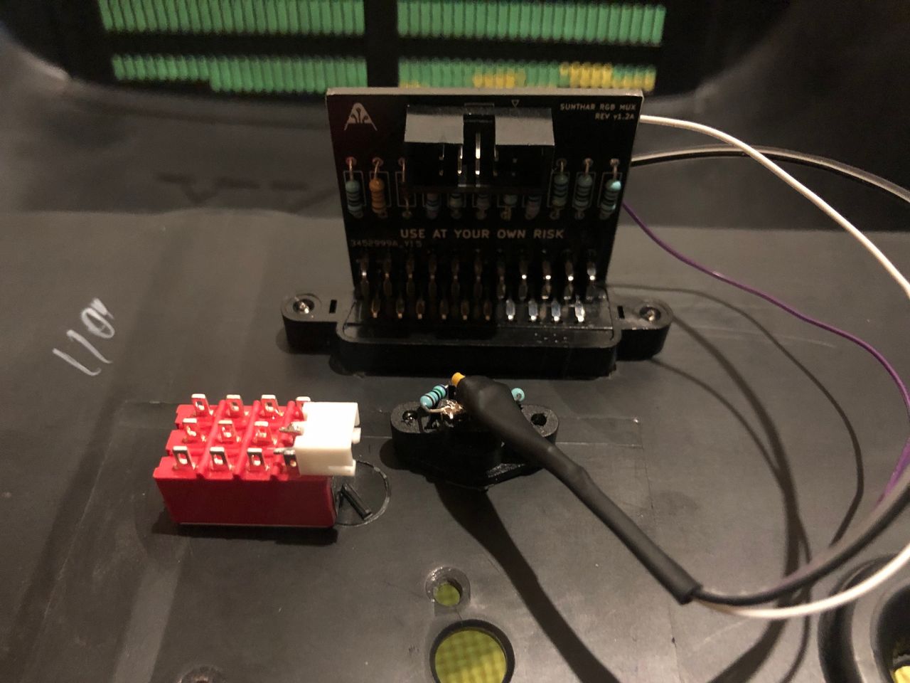
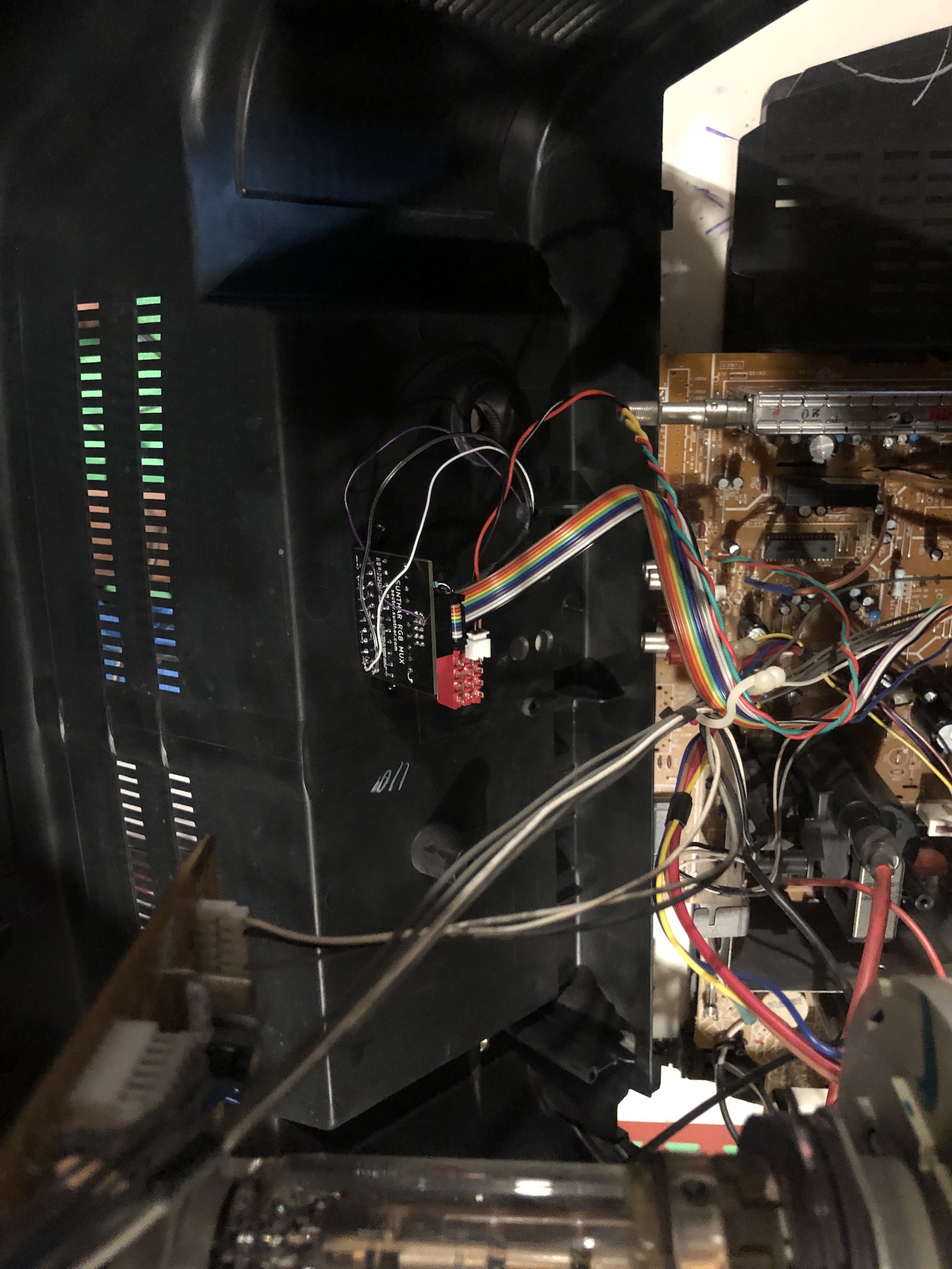
Step 5: Build your mux circuit
Below mod uses the RGB mux board. This is optional, but will make your mod easier and stable. You can also create the circuit presented in the schematics above without the board.
| TV Model | KV-27V20 | KV-27S22 |
|---|---|---|
| Add diodes to RGB lines (on chassis) | No | No |
| Add diode 1N4148 to blanking line (on chassis) | Yes | Yes |
| RGB termination (R1, R2, R3) | 75Ω | 75Ω |
| RGB inline resistors (R4, R5, R6) | 330Ω | 330Ω |
| Audio LR (R7, R8) | 1kΩ | 1kΩ |
| Diode (R9) | 1N4148 | 1N4148 |
| Blanking Ground Resistor (R10) optional | 6.8kΩ | 6.8kΩ |
| Blanking Resistor (R11) | 1kΩ | 1kΩ |
It is important to note that the blanking ground resistor (R10) is necessary to prevent strange black backgrounds from appearing on the KV-27S22 OSD text.
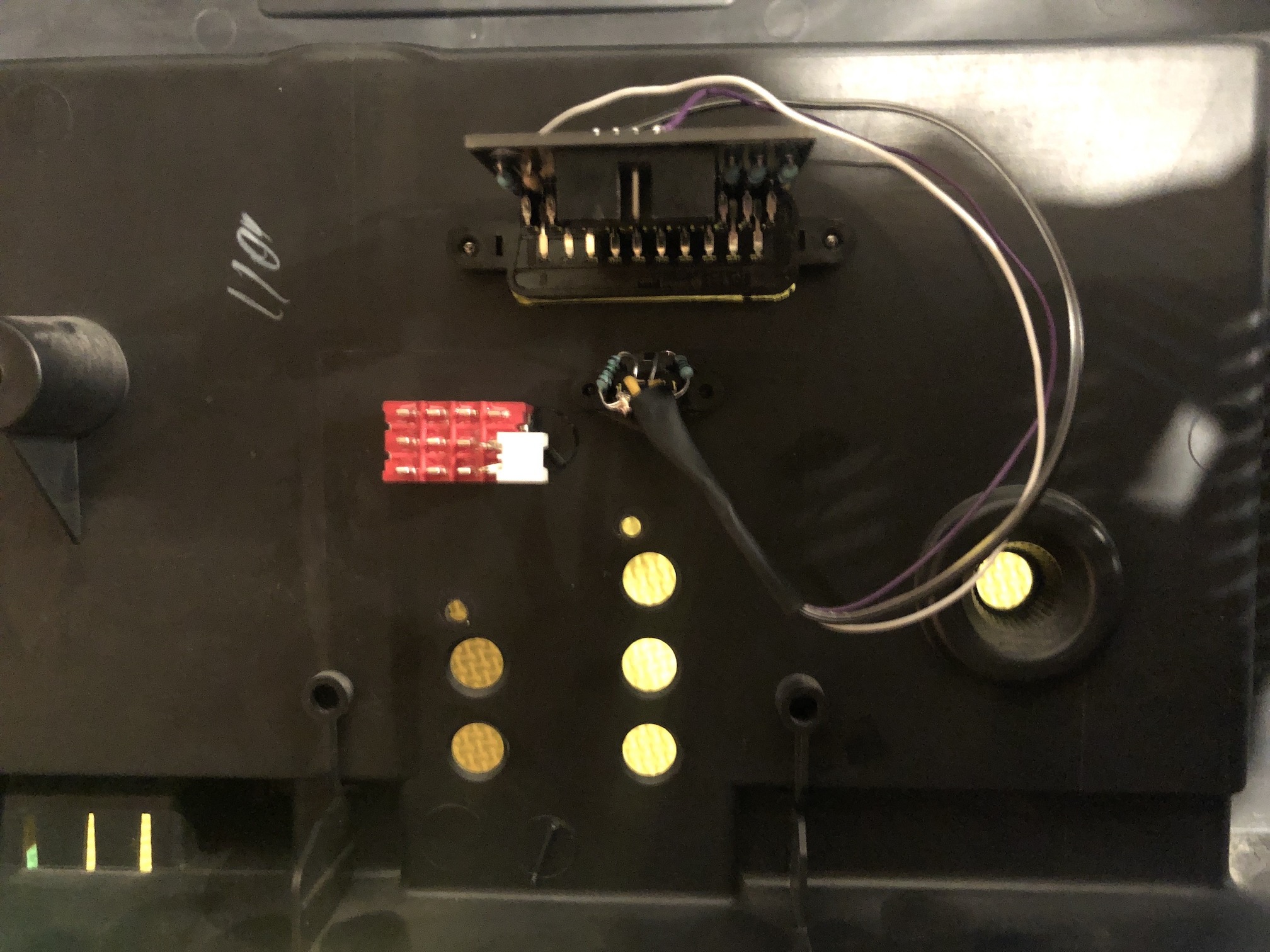
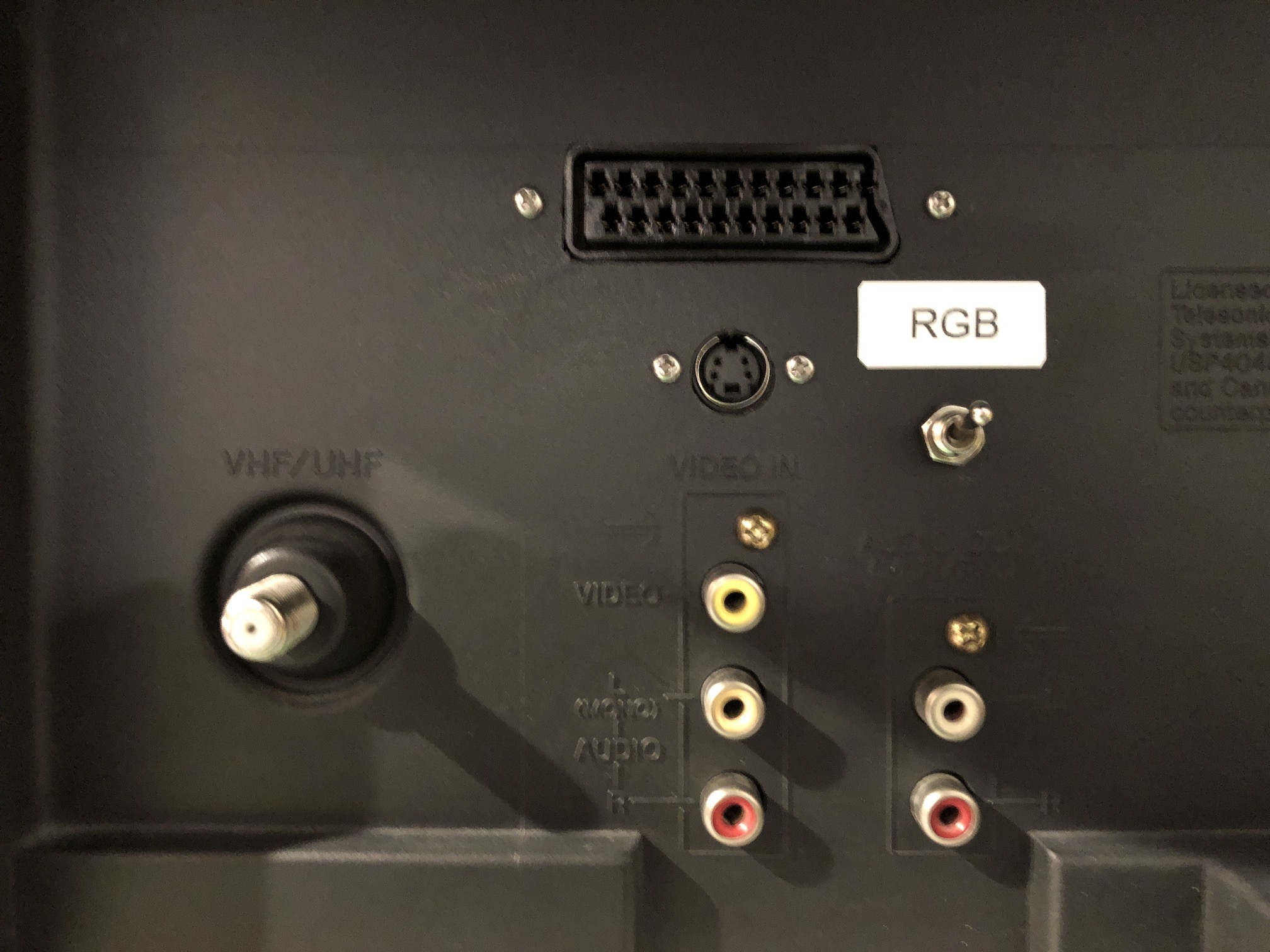
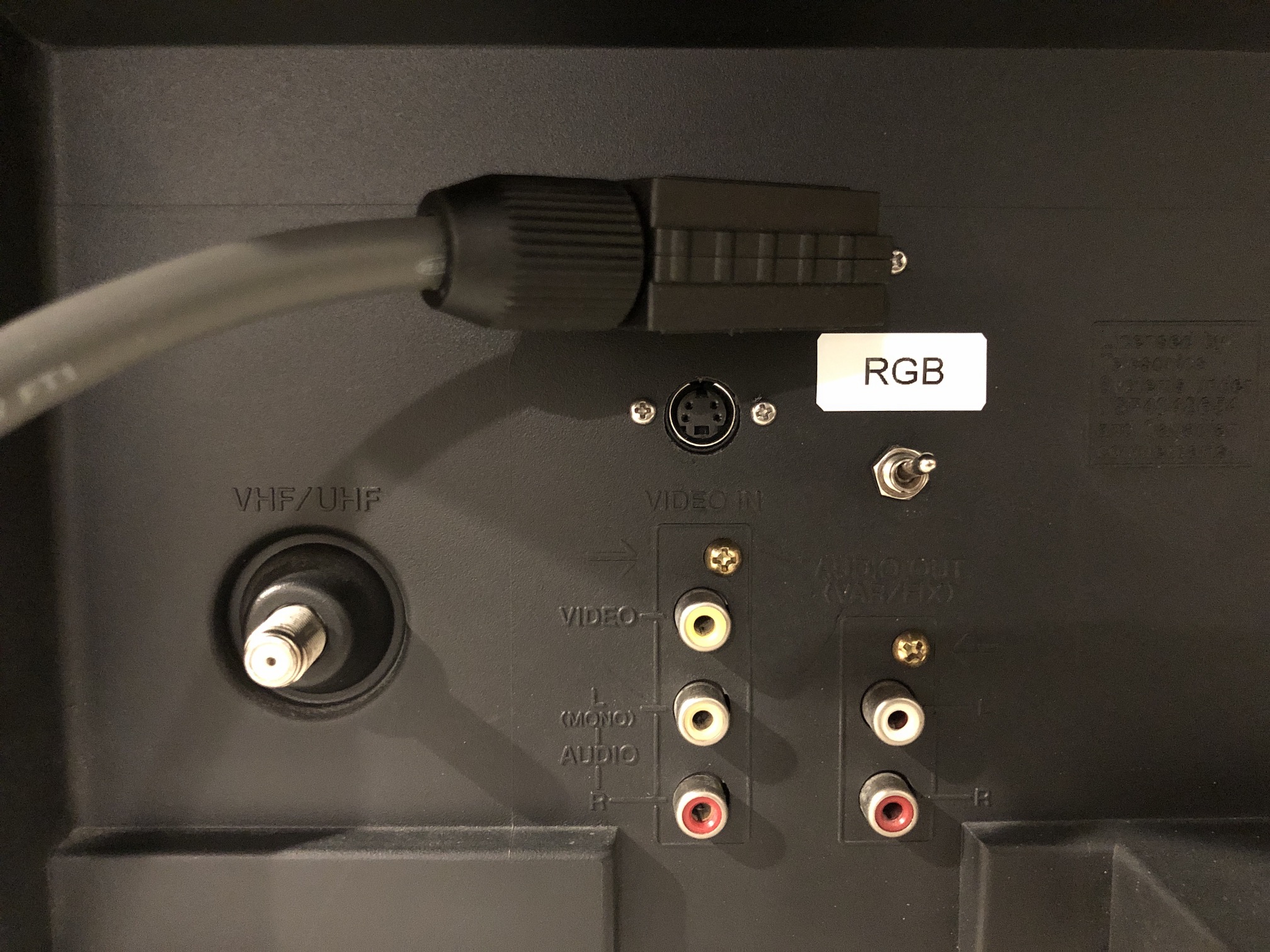
Step 6: Attach the female SCART connector to TV
Creating a SCART cutout and mounting it is an art. I have a dedicated section for it. How to create and mount a SCART female plug?
Purity problem fixed
This CRT suffered from slight purity issues, which was fixed with magnets. Read more about how it was solved here.
Pictures
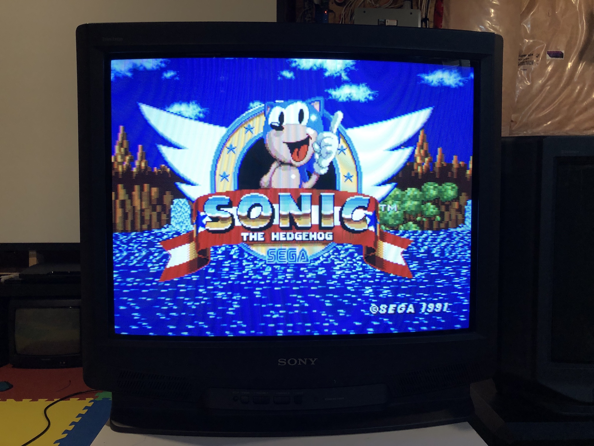
RGB mux mod
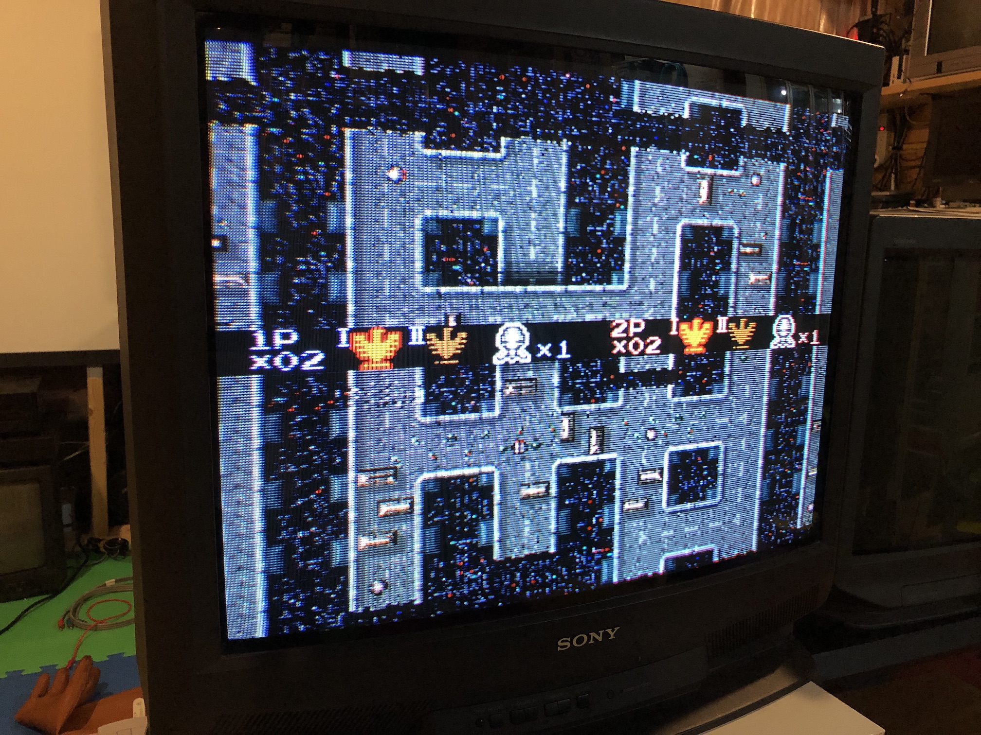
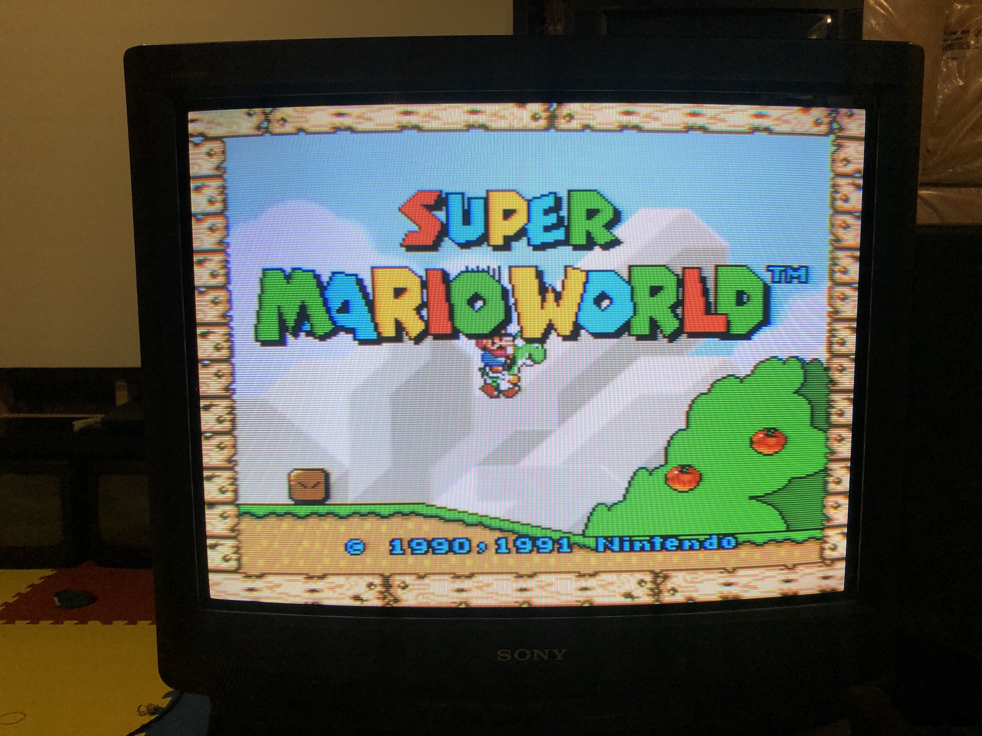
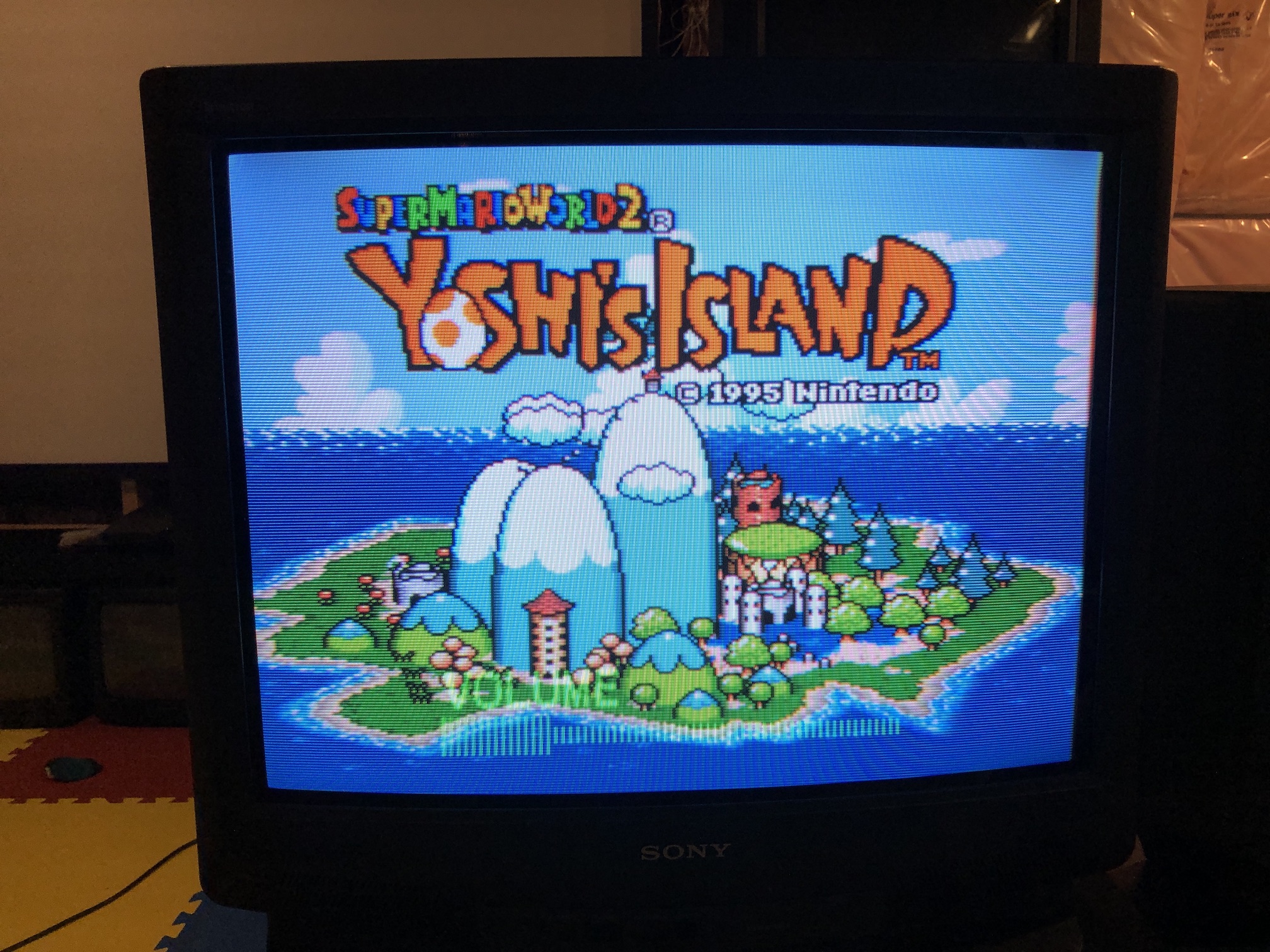
You can see the OSD above an RGB image 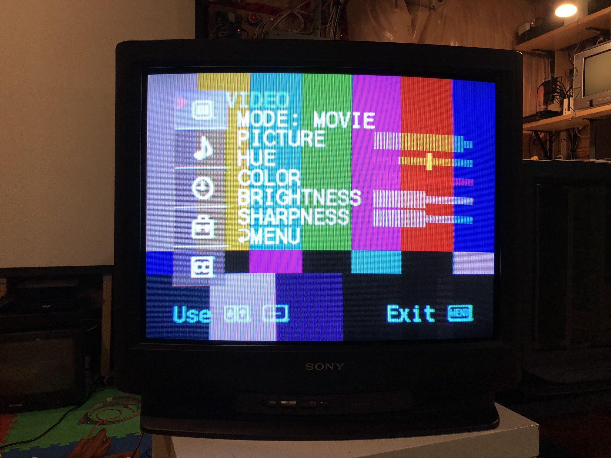
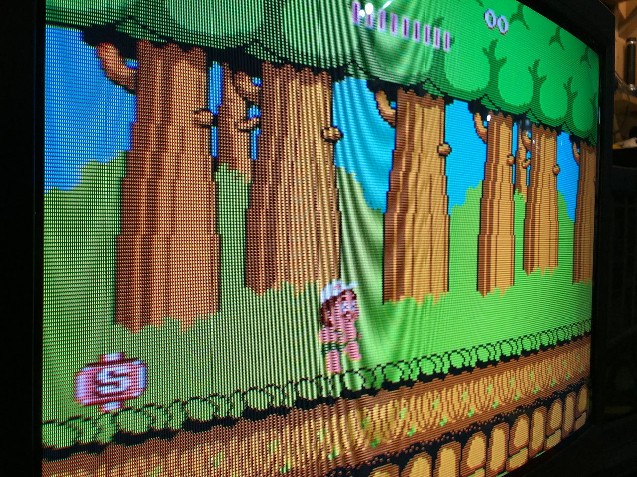
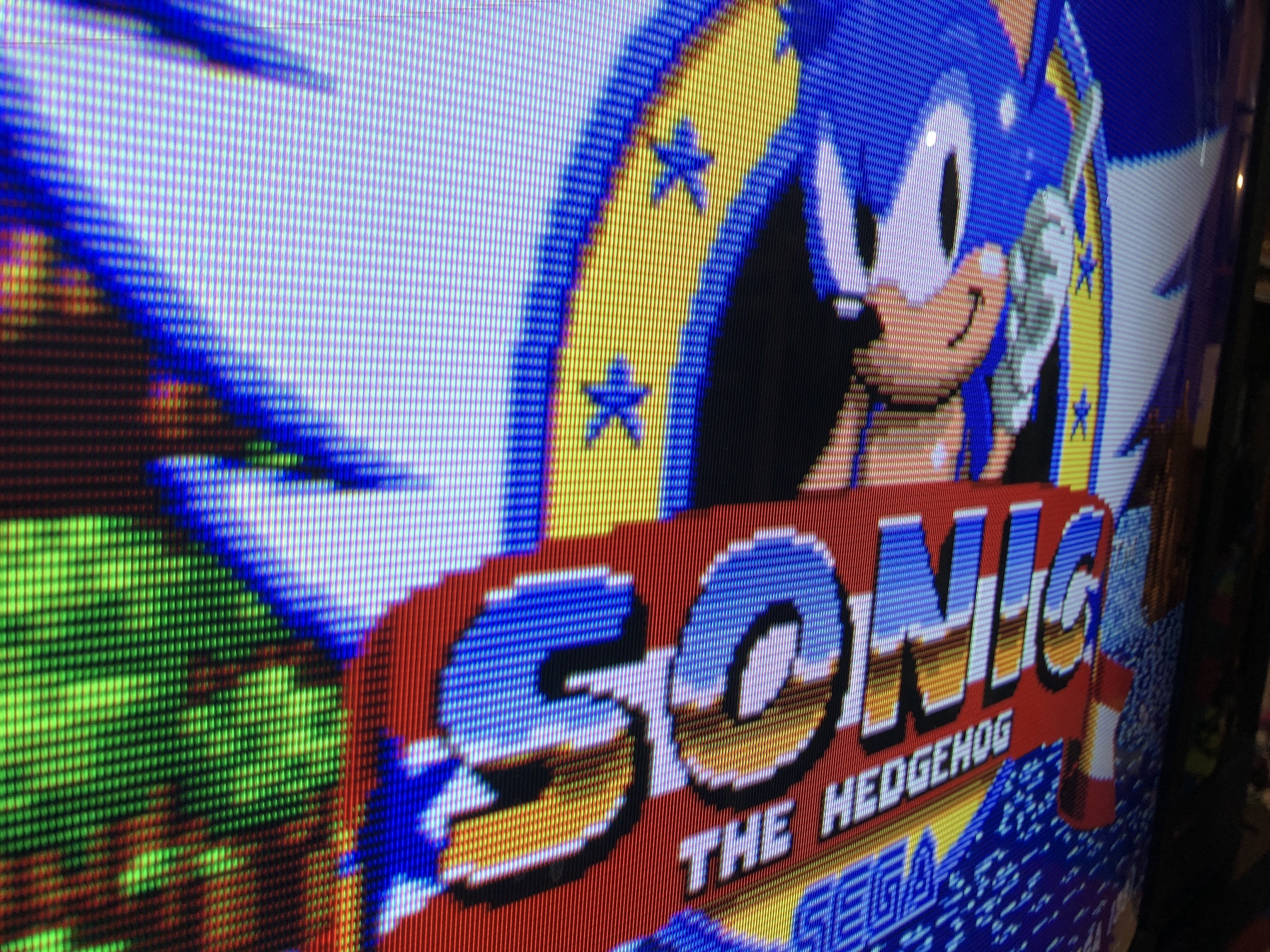
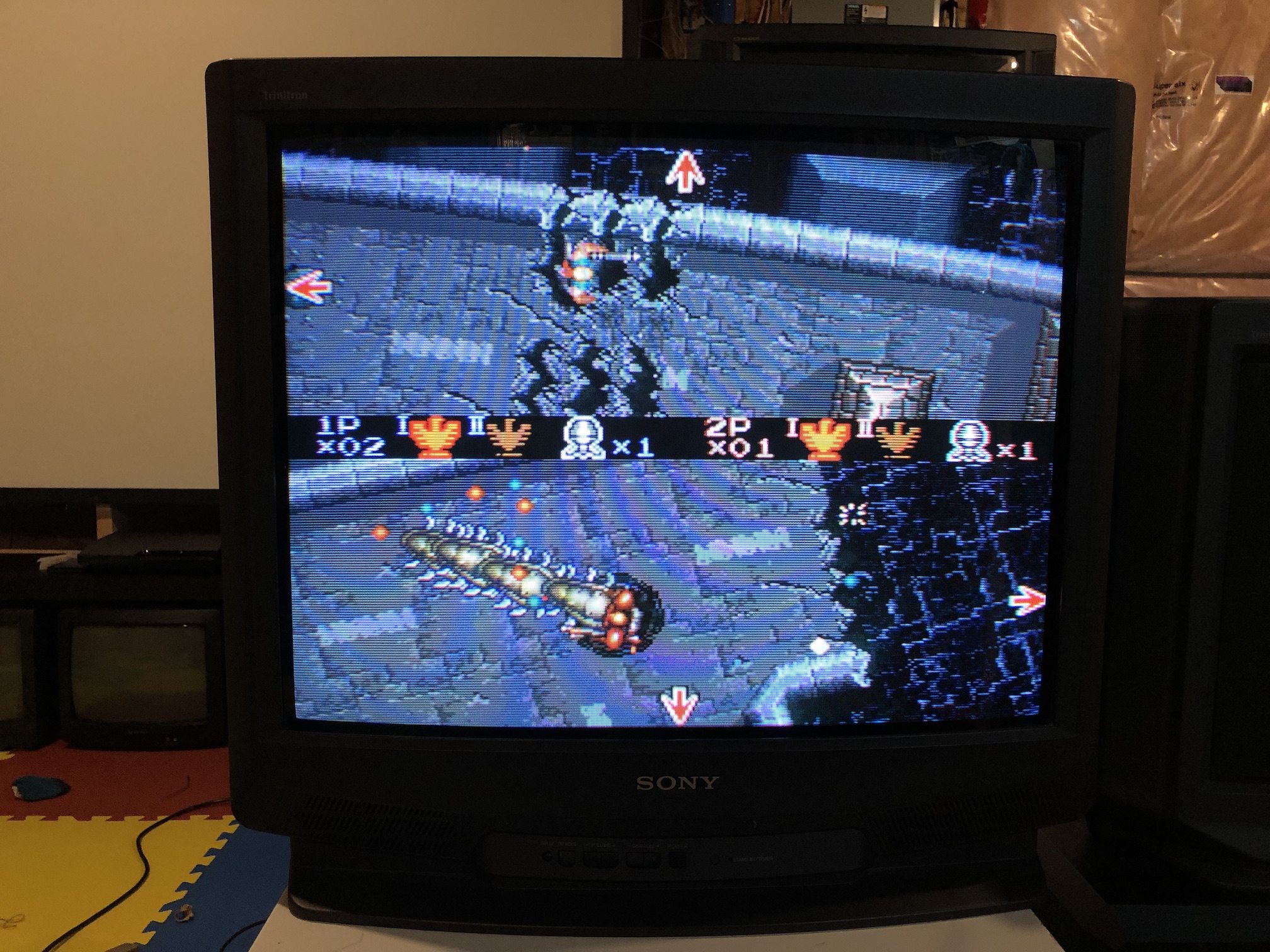
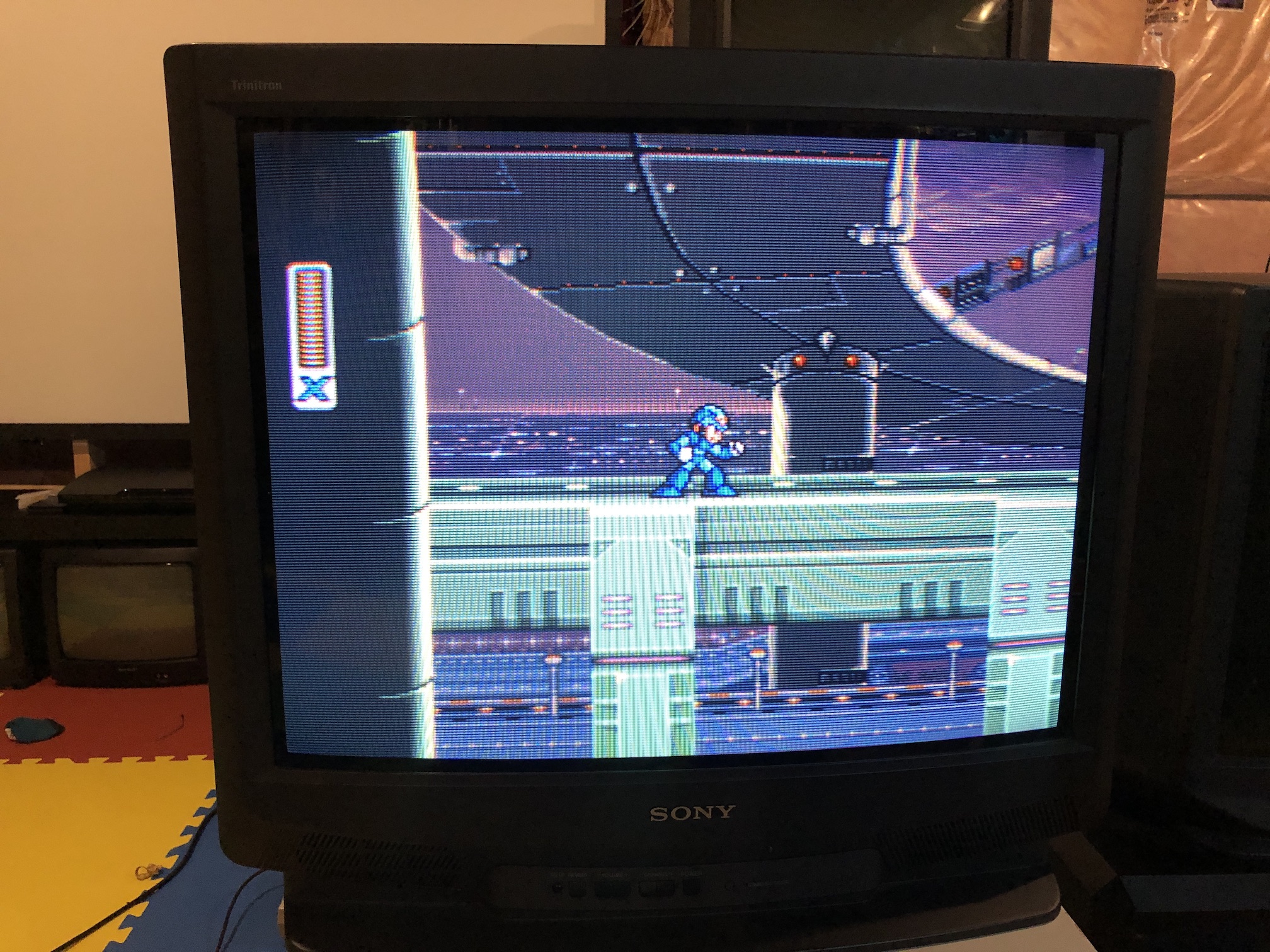
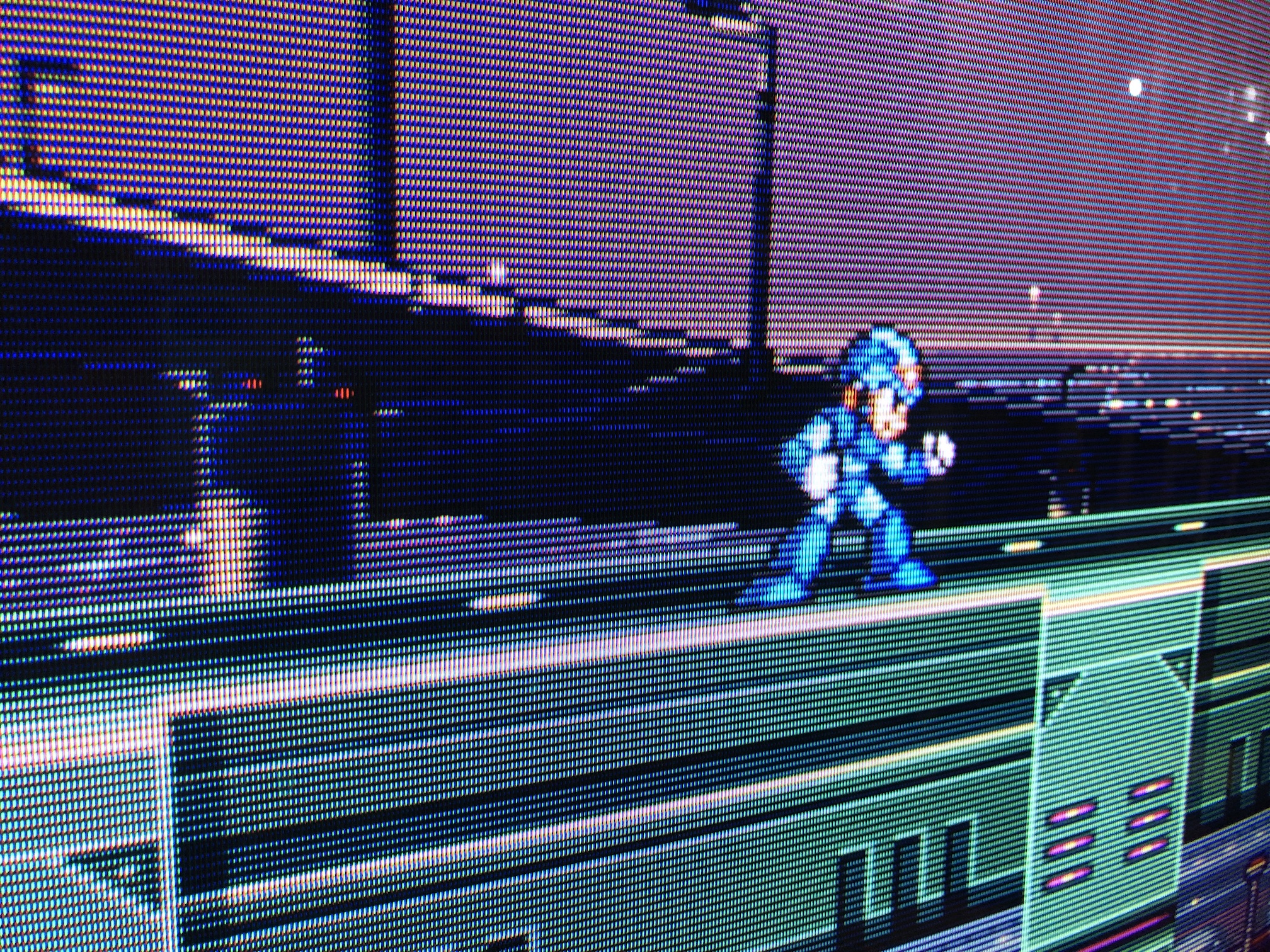
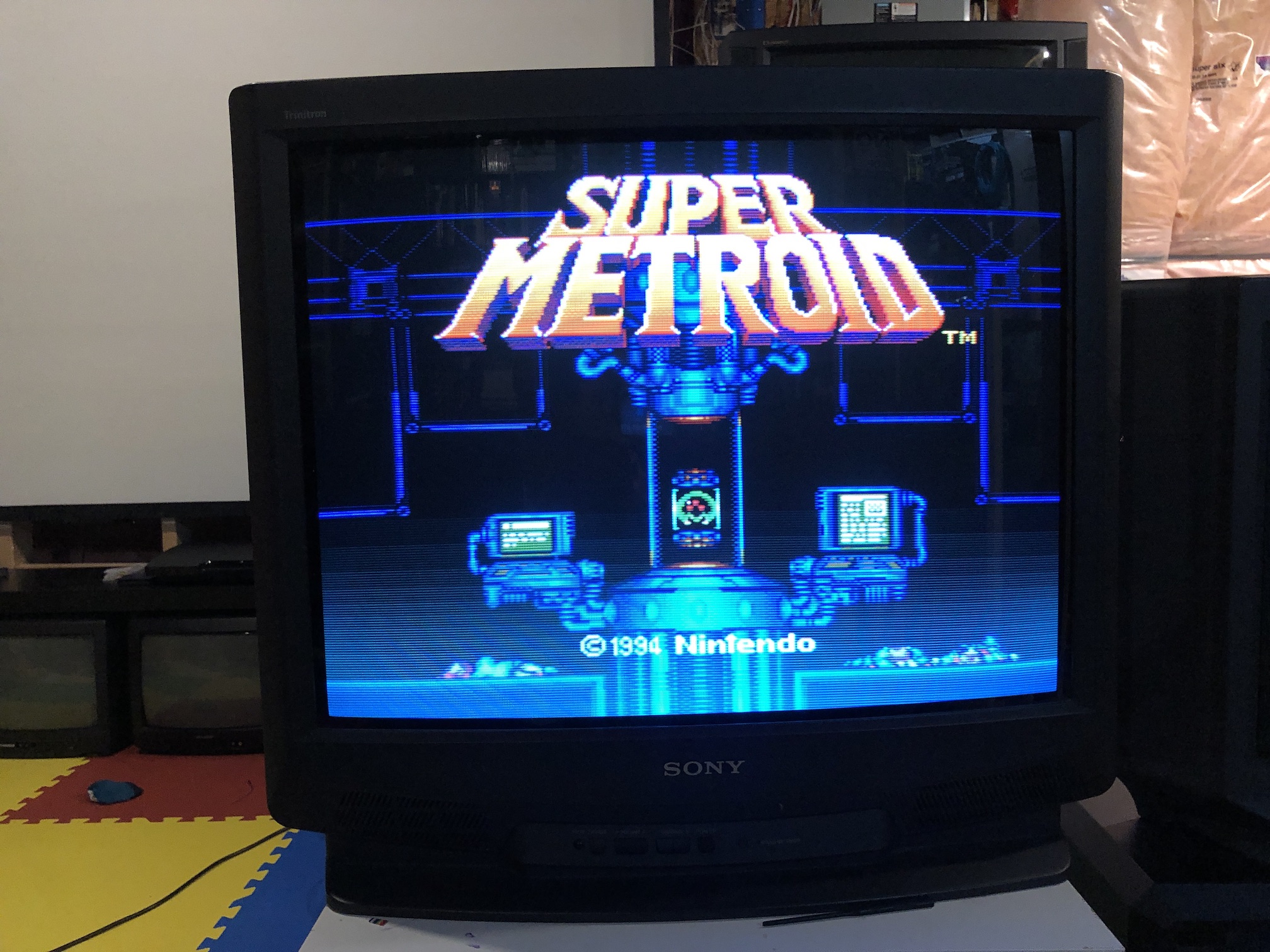
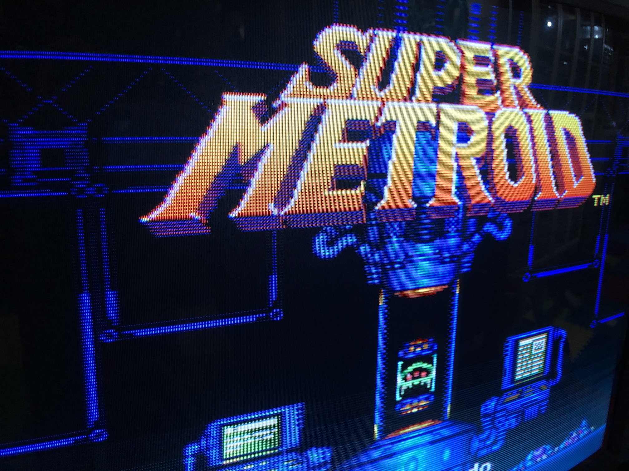
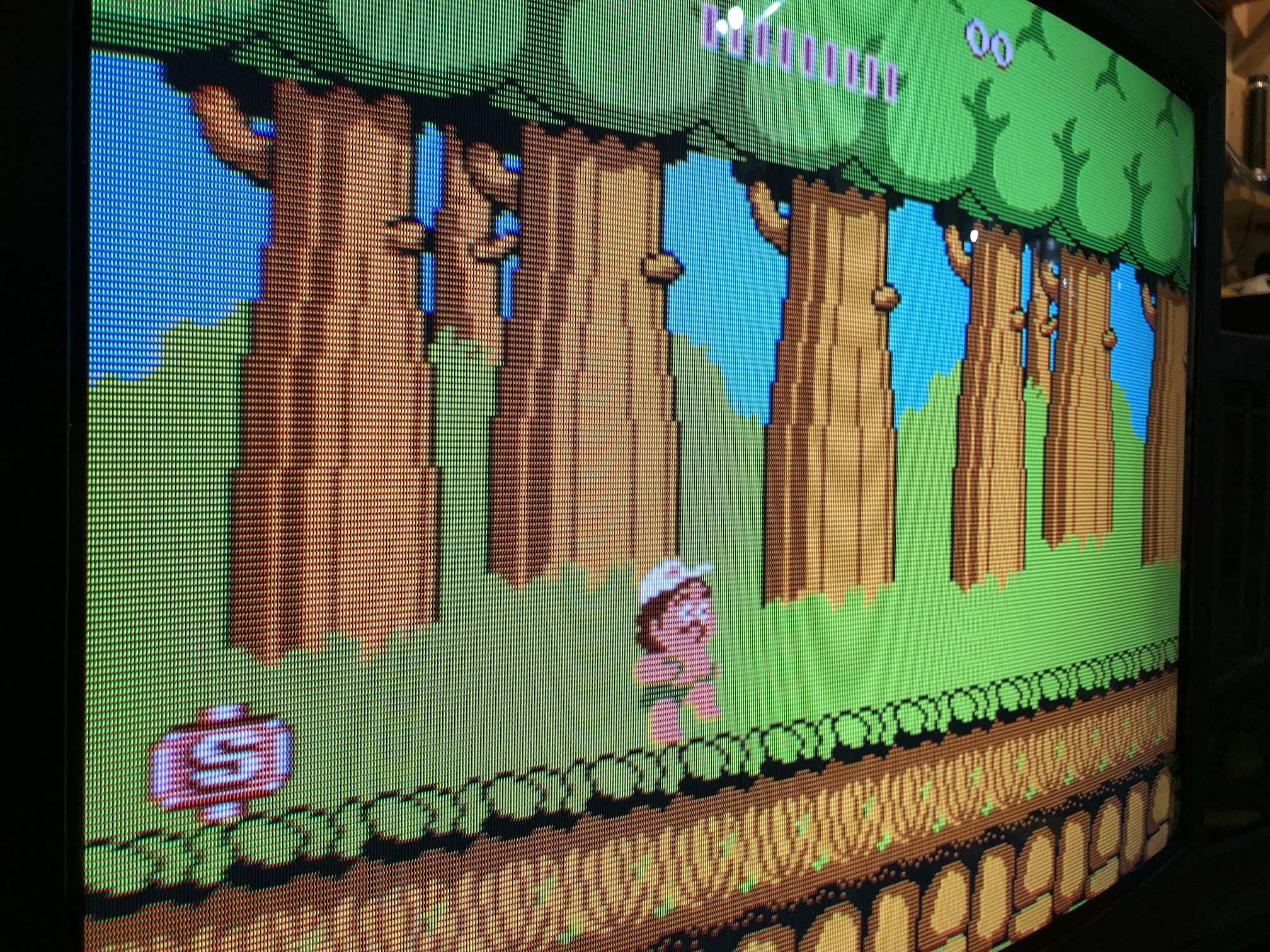
Games
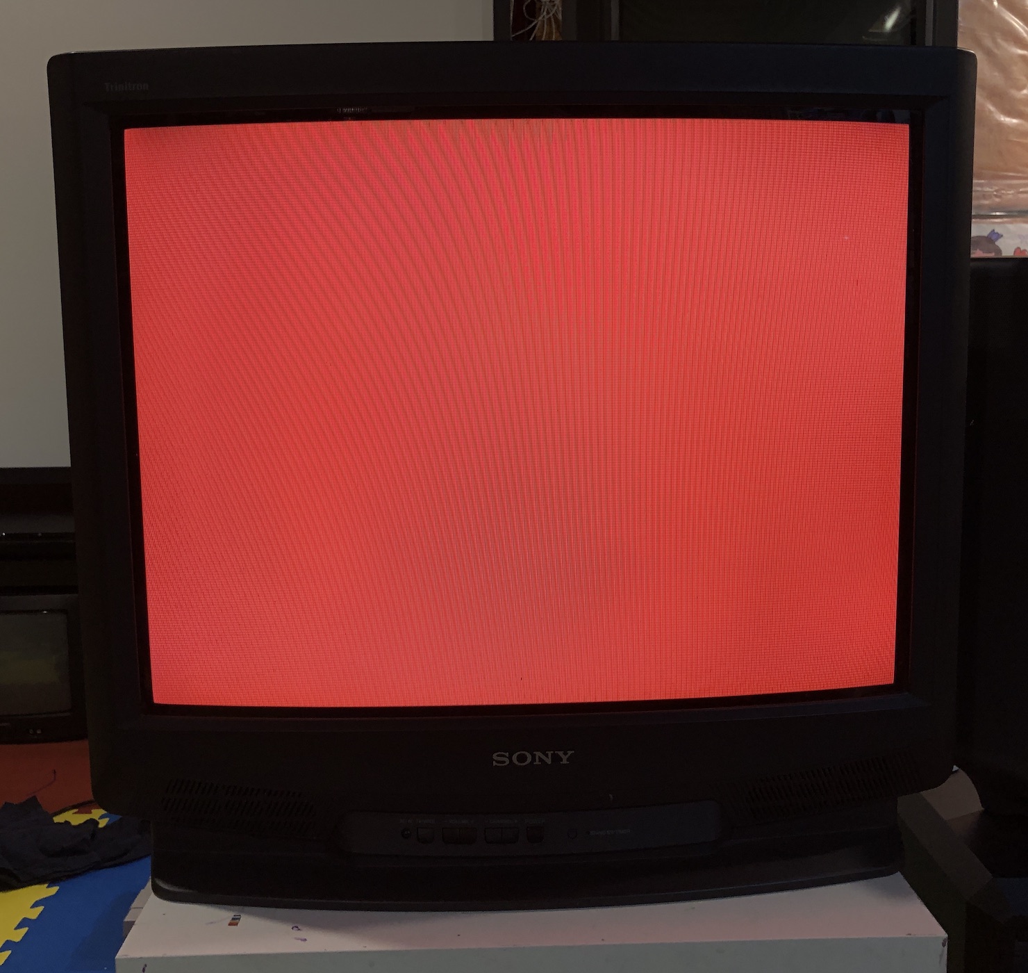
Patterns
Grid 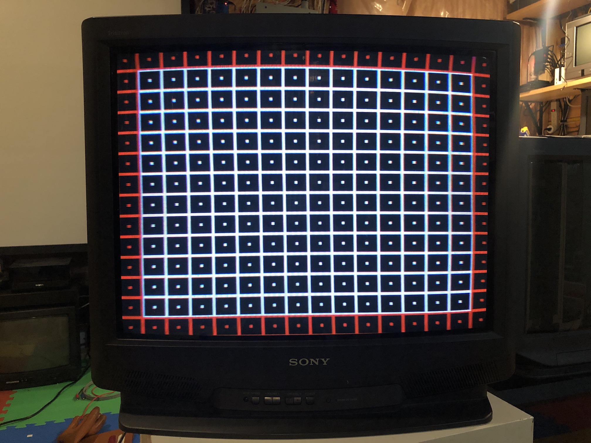
Convergence 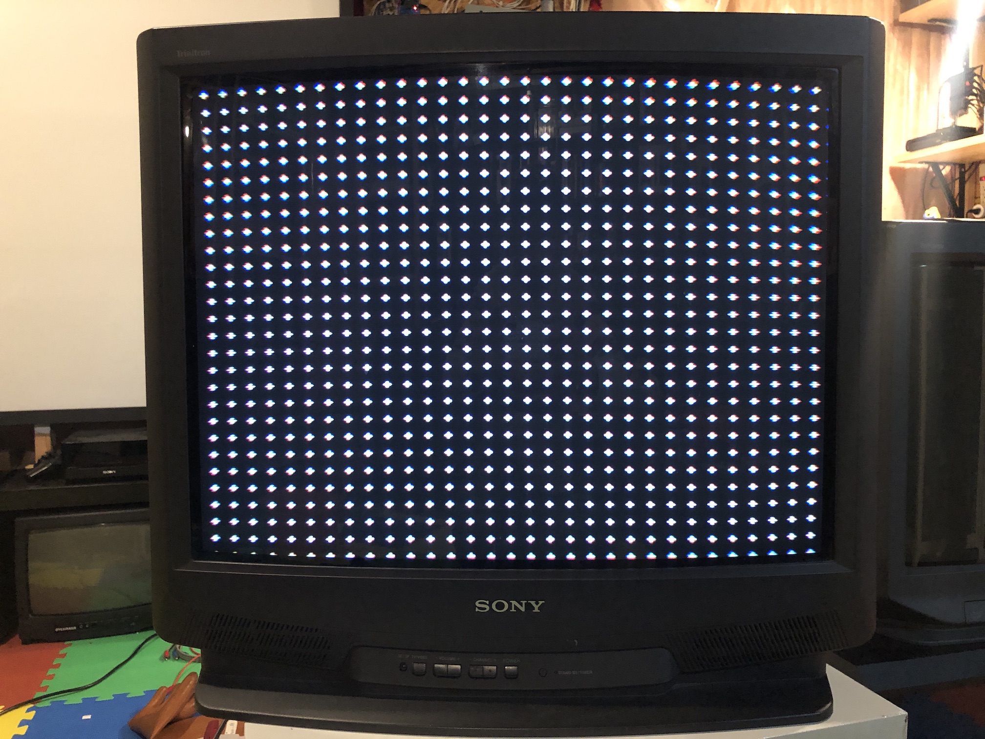
SMPTE 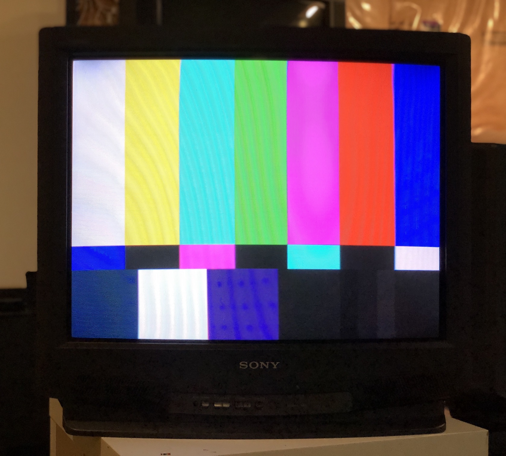
Monoscope 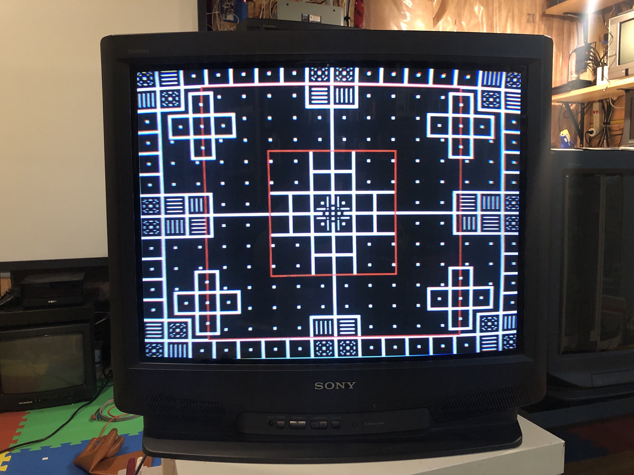
Chassis and Tube
Tube label 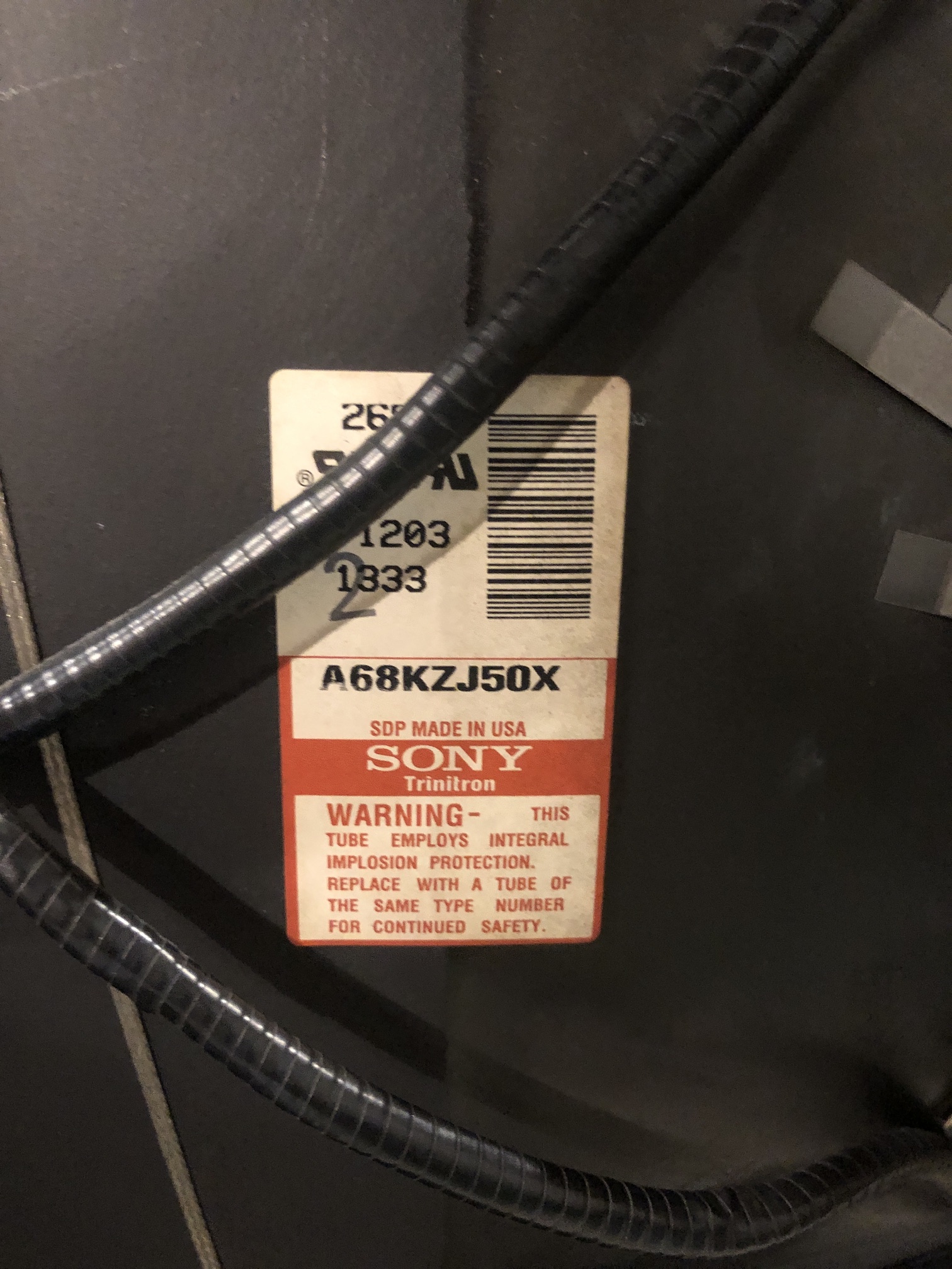
Yoke assembly 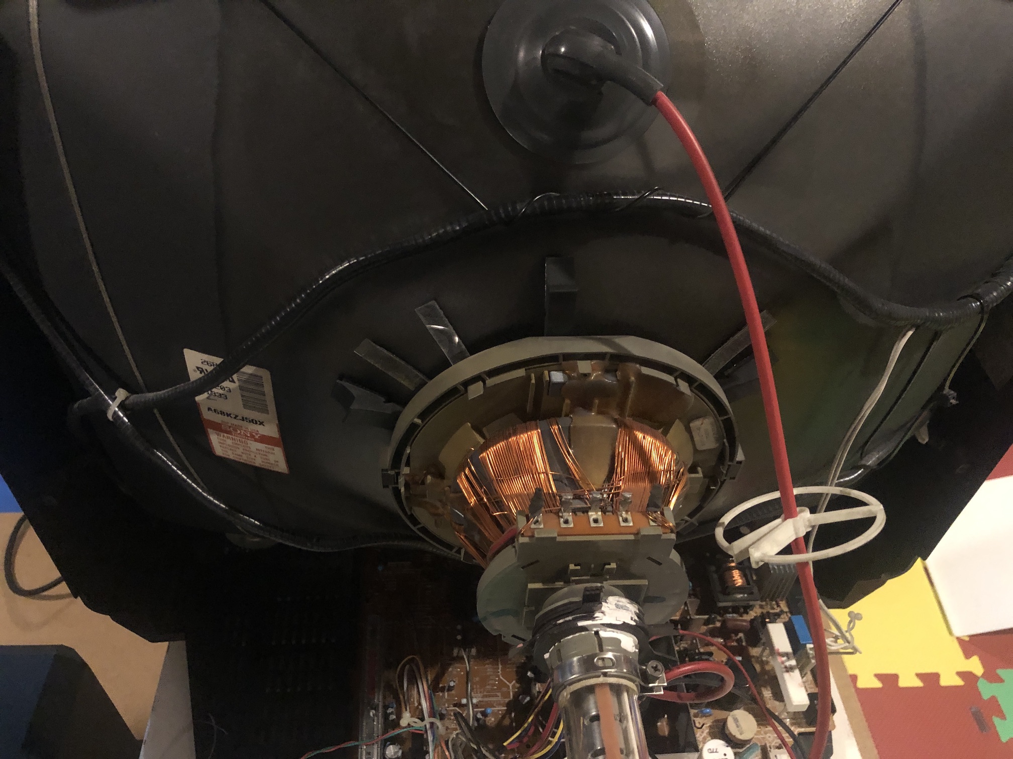
Main chassis - solder side 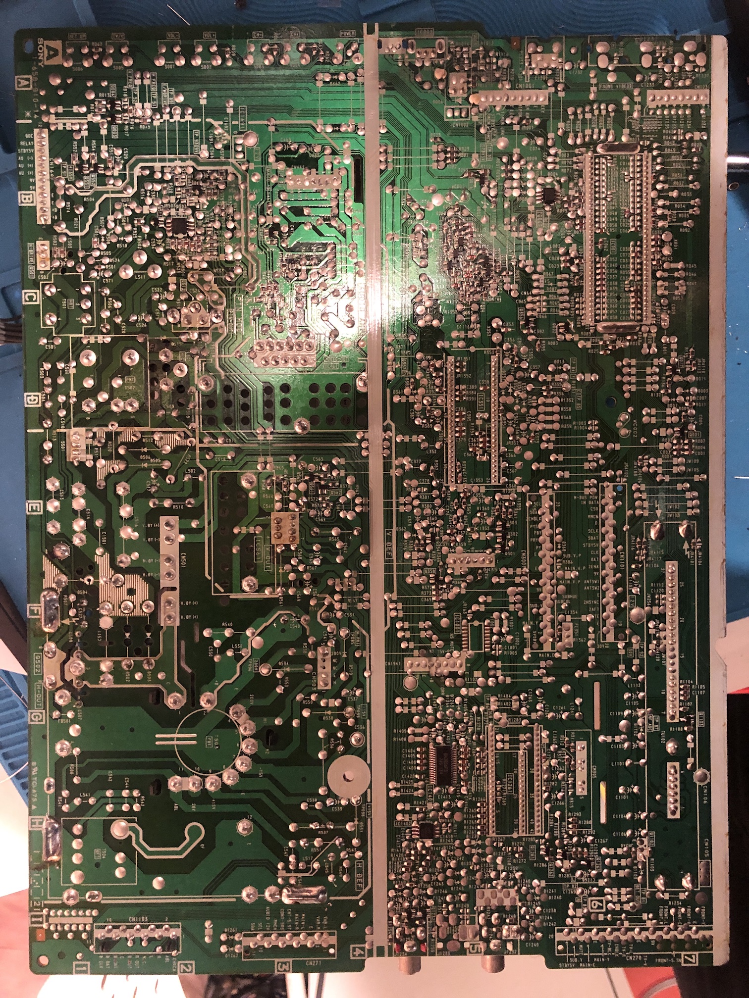
Front buttons 
Back closed 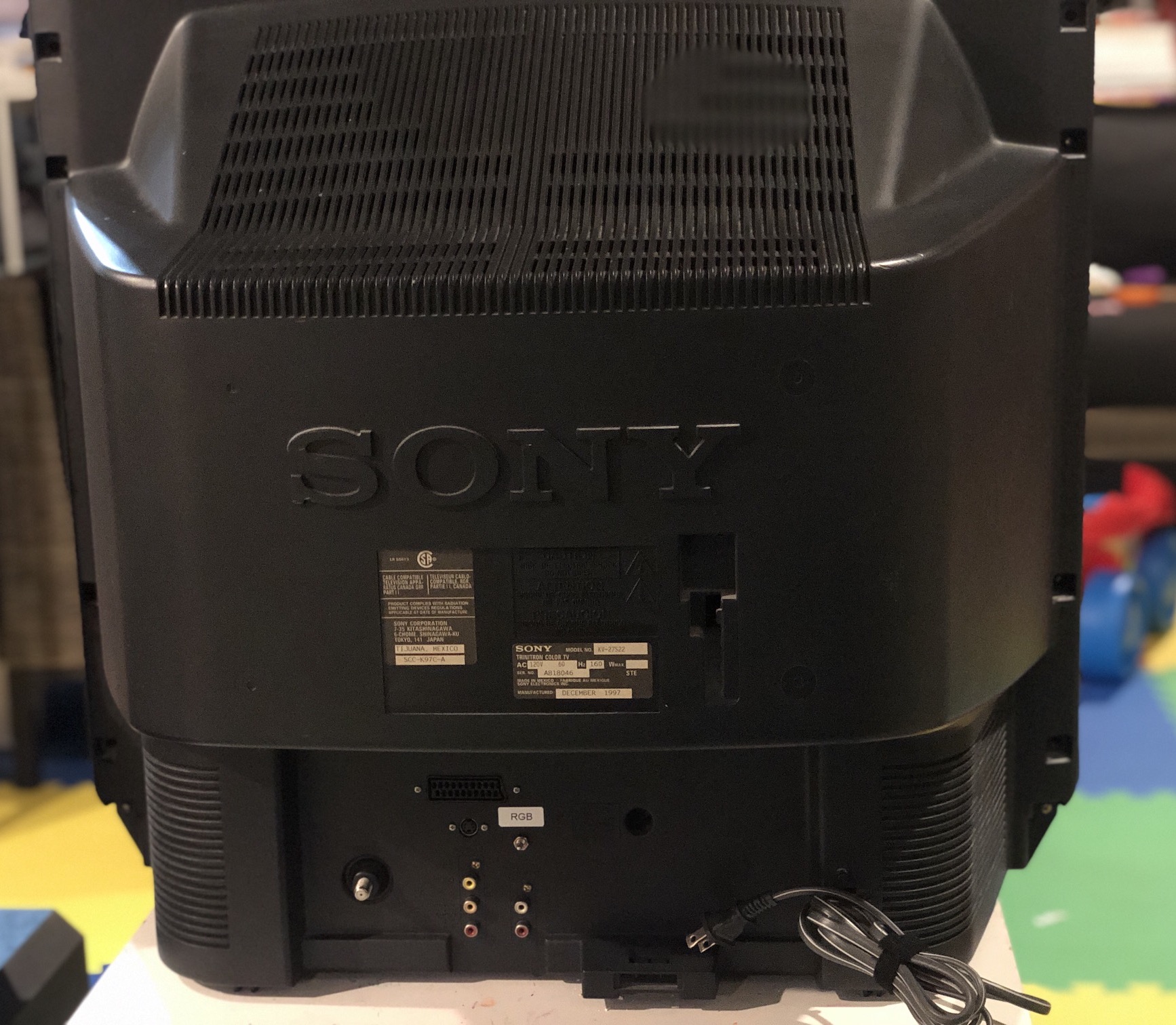
Neck board 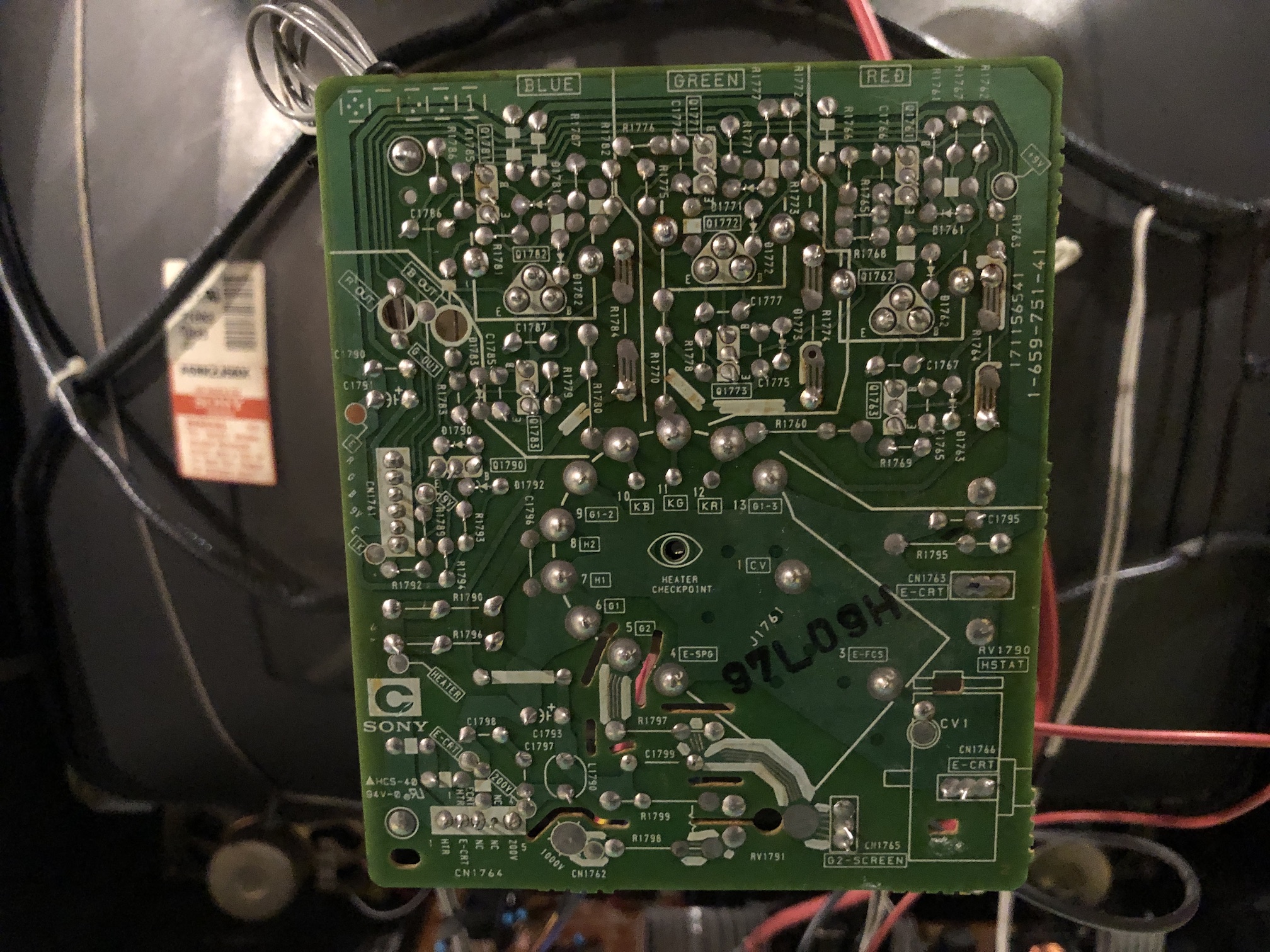
Pictures
Reference Photos