Panasonic CT-9R10
Panasonic CT-9R10 S-Video mod
While this CRT requires an amp to properly RGB mod it, adding Composite and S-Video input to this TV is quite easy to do.
View full CRT details and more mod examples →
Caution
RGB mod is not verified. Panasonics seems to be requiring an RGB amplifier. Therefore, please do not attempt this mod at this time. Below details just show the attempt made.
Contributors
Thank you to everyone who contributed to this guide:
- manadream's console and CRT mods and repair — photos and documentation
CRT safety
Caution
You can die doing this! So read carefully! CRT TV is not a toy. Do not open a CRT TV. If you don't have any prior knowledge about handling high voltage devices, this guide is not for you. CRT TV contains high enough voltage (20,000+ V) and current to be deadly, even when it is turned off.
Plan of attack
Manuals and Datasheets
No manuals or datasheets available yet.
Specs
- Year: 1998
- Chassis: ANDP243
- Jungle Chip: AN5163K
Schematics
Get hold of the schematics for your TV. Understand where the RGB and Fast Blanking signals go from OSD to the Jungle (Chroma) chip.
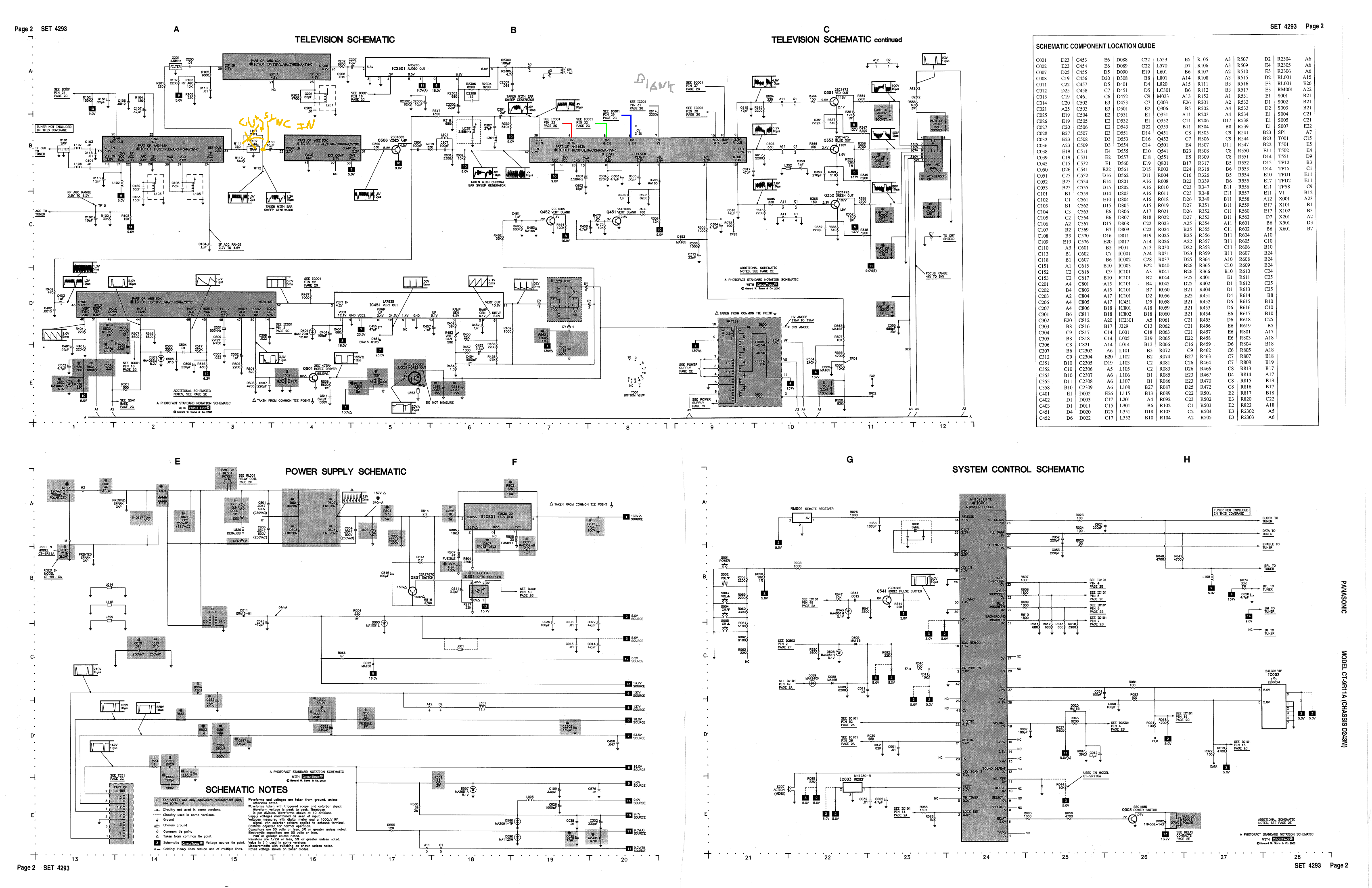
Notes: RGB mod for this set is not yet confirmed.
RGB mux diagram
Prepare the mux diagram. If you are building your own circuit, this diagram should help.
Performing the mod
While this set is RGB moddable, it requires amplified RGB signal to work properly. None of my existing kits would work well with this model.
Checking the blanking signal with the voltage divider, around 3.4V is being sent to the jungle chip for blanking.
Also on the RGB lines around 1.37V is being sent to the jungle chip. This is an unconventional voltage.
Service Menu
Service Menu Default values
- B0 - 40
- B1 - 33
- B2 - 33
- B3 - 25
- B4 - 8
- B5 - 5
- C0 - 6 (H position) > 10
- C1 - 121 (R cutoff)
- C2 - 138 (G cutoff)
- C3 - 70 (B cutoff)
- C4 - 64
- C5 - 85
Pictures
Photos by manadream's console and CRT mods and repair

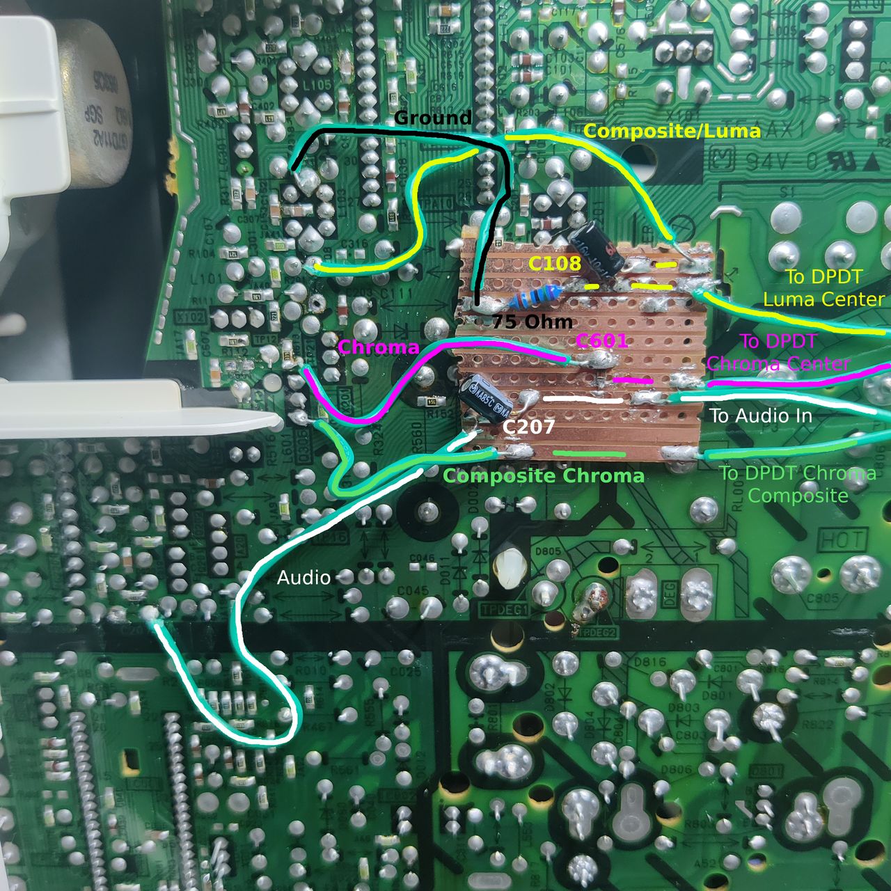
I used a spare stripboard to make the connections easier. I also 75 Ohm terminated Composite/Luma here instead of at the connector, but you can terminate it at the connector instead. Notice C601 is inline with the Chroma connection as in the schematic.
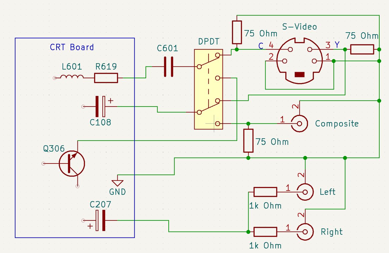
Schematic of the full install. Note that C207 has the negative (-) side lifted from the CRT board, as is C108's positive (+) side, but the other side remains in the board. C601 is completely removed from the CRT board and put in-line with the Chroma signal from the DPDT, which is then connected to the side of R619 that was originally connected to C601.

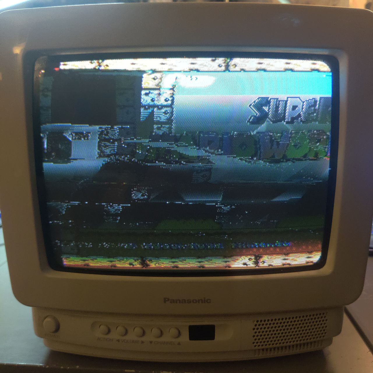
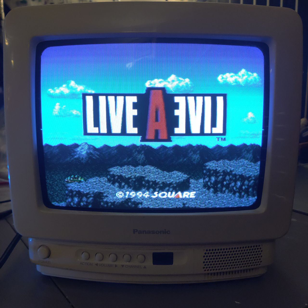
If you see something like this, you are having sync issues and it is likely because of microfractures in one of the solder joints. I reflowed all the pins on the jungle chip and it fixed this issue.
Reference Photos