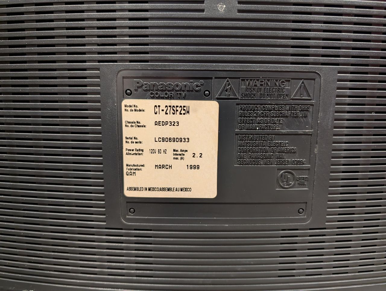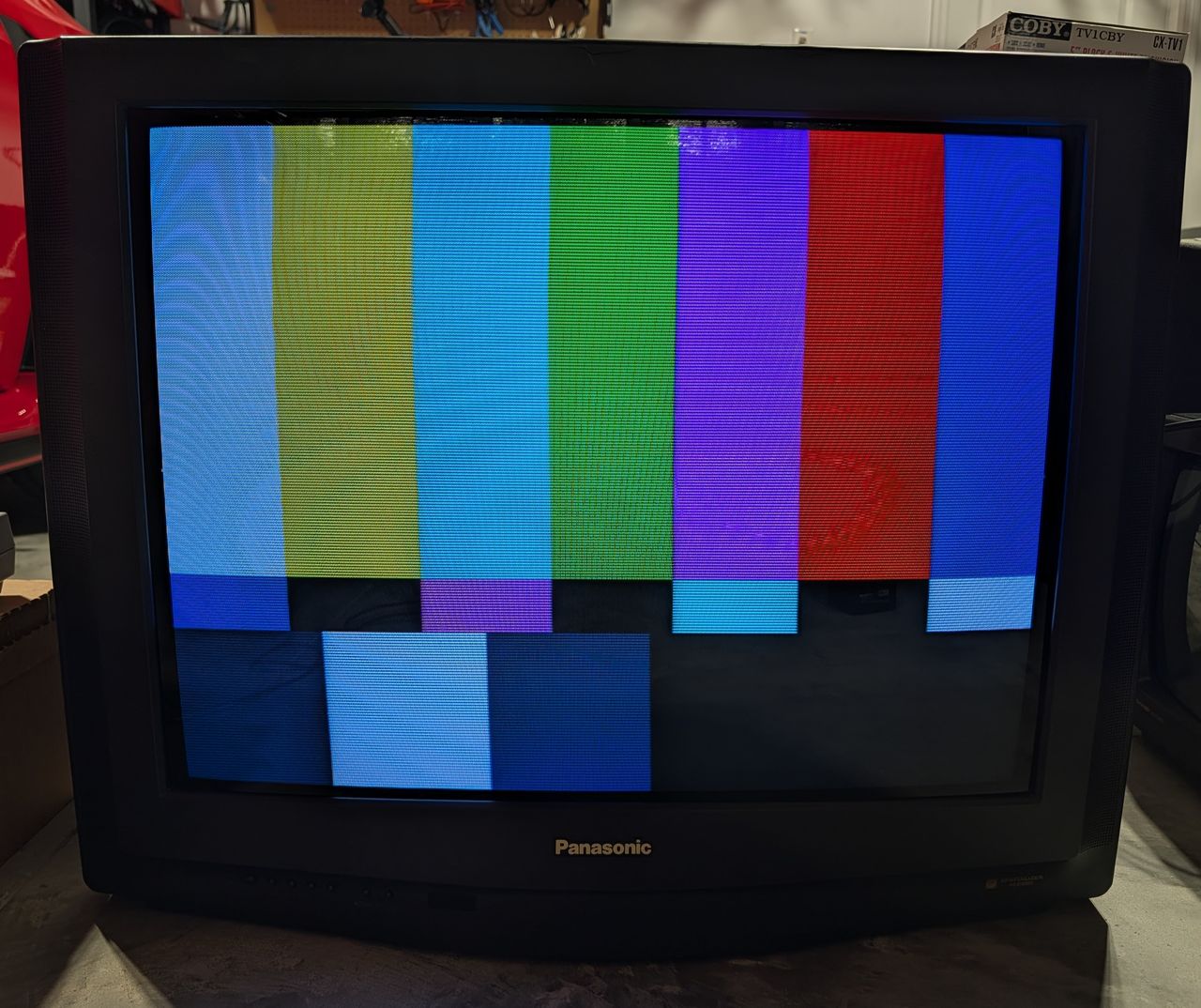
Panasonic CT-27SF25W
Panasonic CT-27SF25W CRT RGB mod
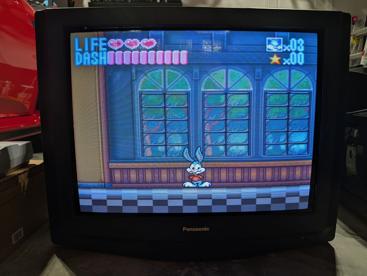
This tutorial covers the RGB mod for Panasonic CT-27SF25W.
View full CRT details and more mod examples →
Contributors
Thank you to everyone who contributed to this guide:
- Nostalgia FX Workshop — photos and documentation
CRT safety
Caution
You can die doing this! So read carefully! CRT TV is not a toy. Do not open a CRT TV. If you don't have any prior knowledge about handling high voltage devices, this guide is not for you. CRT TV contains high enough voltage (20,000+ V) and current to be deadly, even when it is turned off.
Plan of attack
Manuals and Datasheets
- Panasonic CT-27SF25W Service Manual
- Panasonic AN5308NK Datasheet (Jungle)
- Panasonic MN102L35GTD2 Datasheet (OSD)
Specs
- Year:
- Jungle Chip: Panasonic AN5308NK
- OSD Chip: Panasonic MN102L35GTD2
- Screen Size: 27"
RGB mux diagram
Performing the mod
Detailed mod instructions to be added.
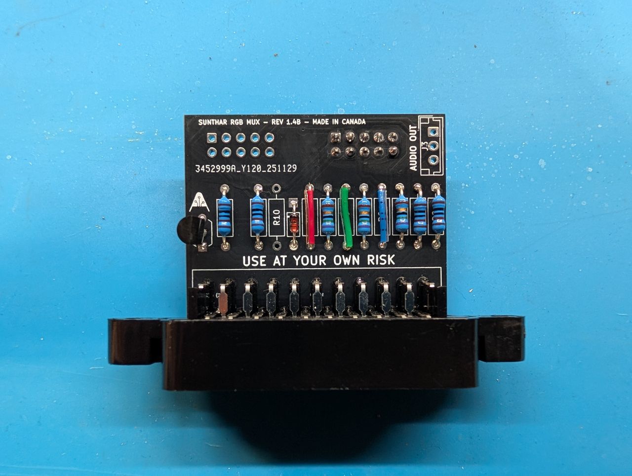
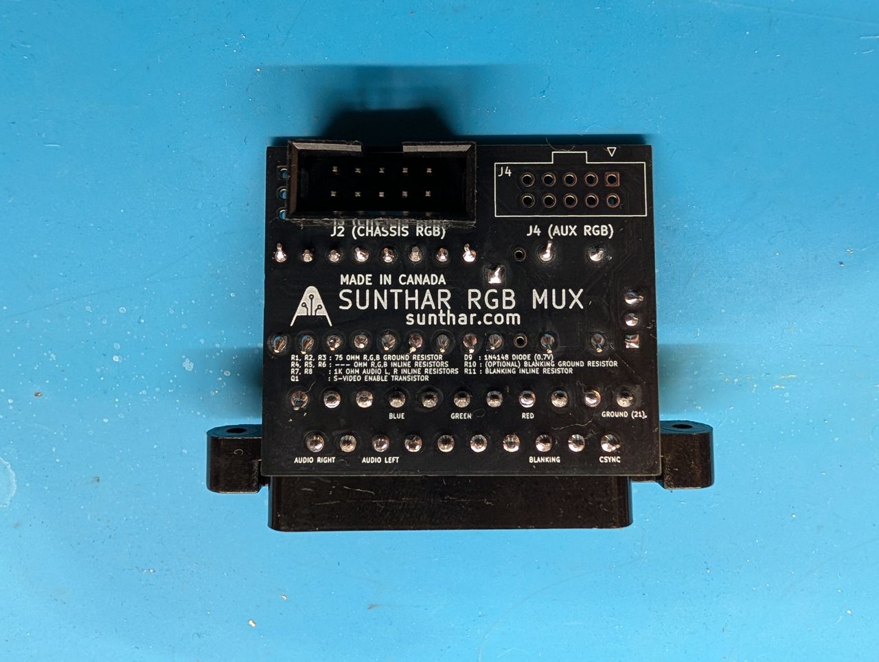
This mod uses the RGB mux board. This is optional, but will make your mod easier and stable. You can also create the circuit presented in the schematics above without the board. Please also checkout the mux calculator to play with your own values.
| Component | Value |
|---|---|
| RGB/OSD inline resistor (chassis) | 0μF |
| Removed RGB/OSD resistor (chassis) | 120Ω |
| RGB inline diode method (chassis) | No |
| 0.1μF caps replaced (chassis) | No |
| RGB termination (R1, R2, R3) | 75Ω |
| RGB inline (R4, R5, R6) | 0μF |
| Audio LR (R7, R8) | 1kΩ |
| Diode (R9) | 1N4148 |
| Blanking Ground Resistor (R10) | open |
| Blanking Resistor (R11) | 1kΩ |
| Transistor Base Resistor (R12) | 1kΩ |
| Transistor (Q1) | PN2222A |
Pictures
Photos by Nostalgia FX's Sector
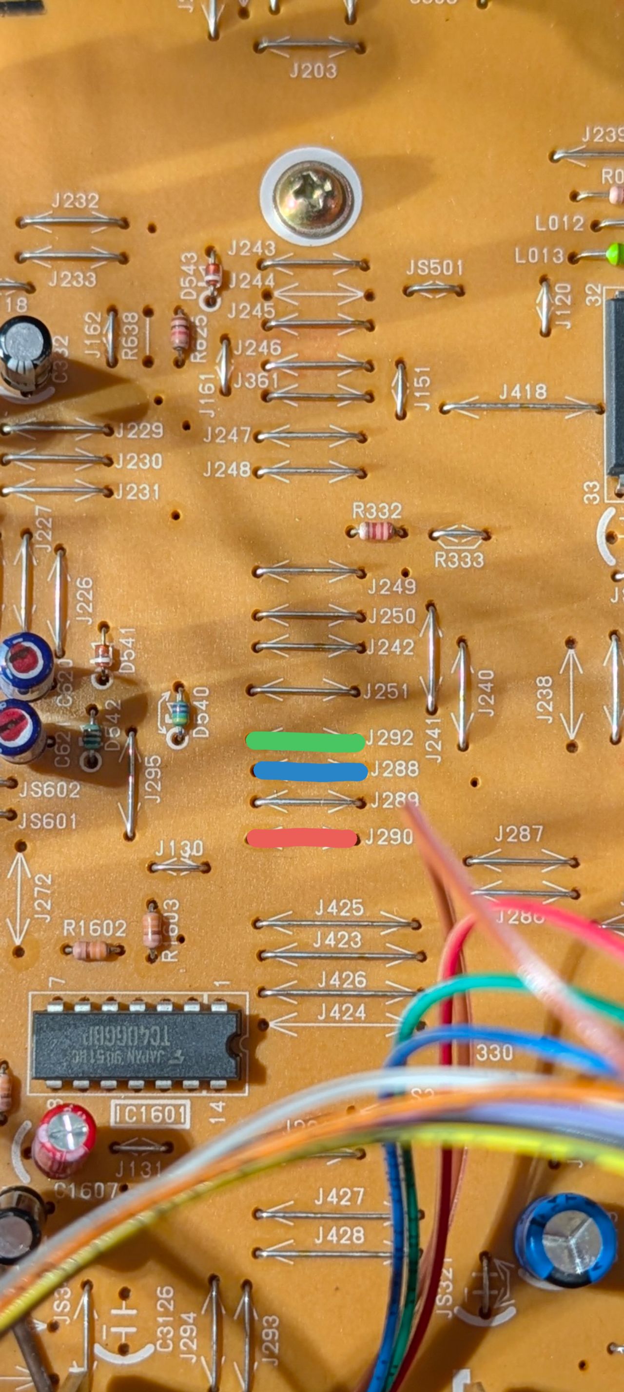
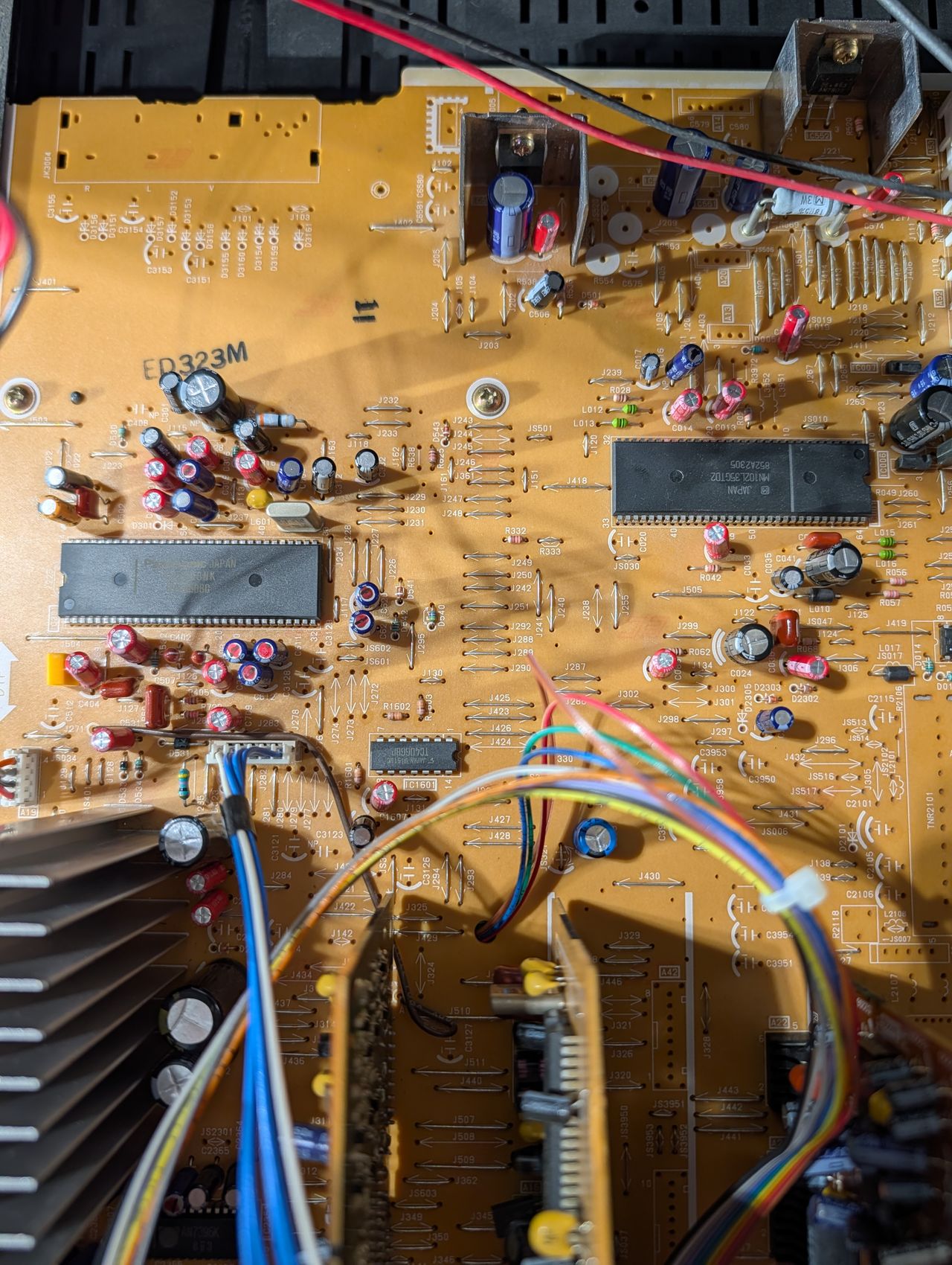
Topside of the A-Board with the three jumper pins highlighted corresponding to the RGB lines
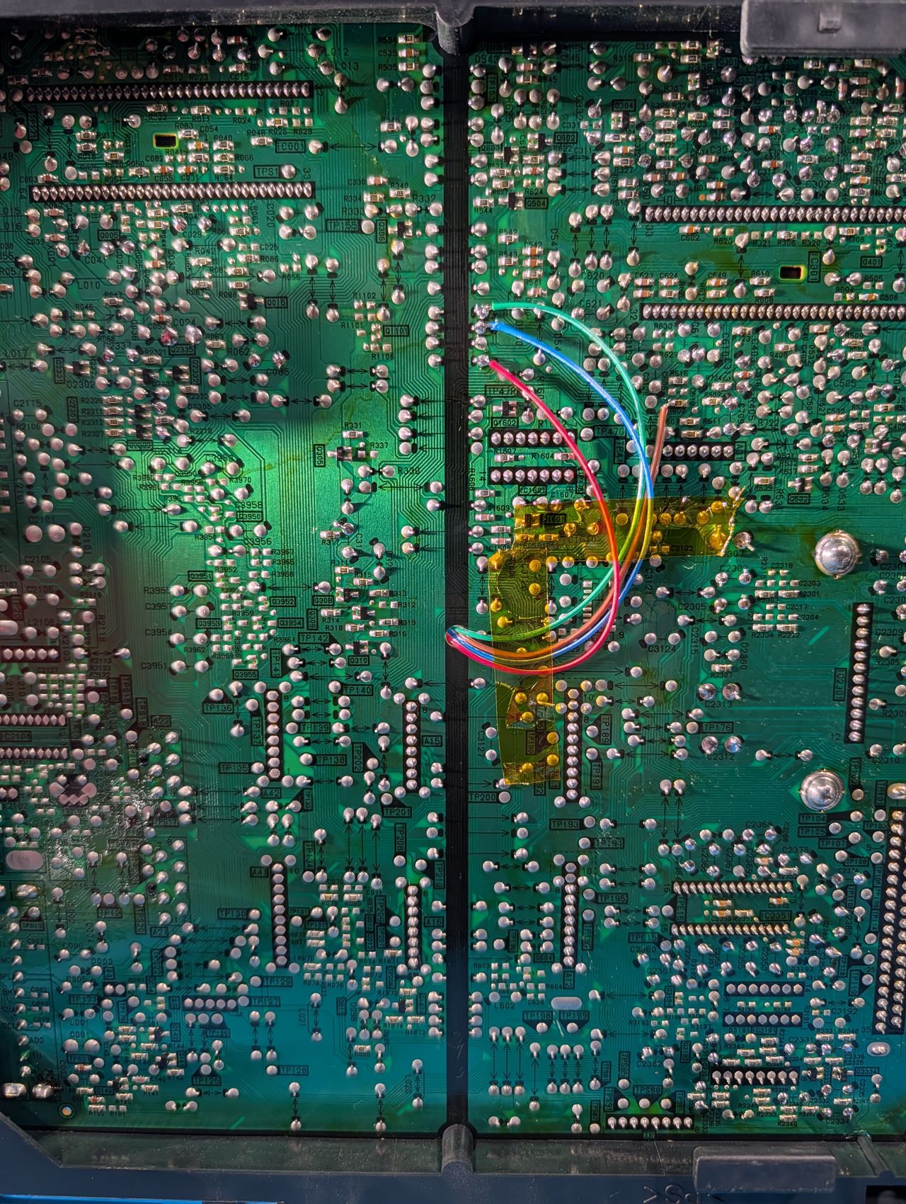
Bottom of A-Board
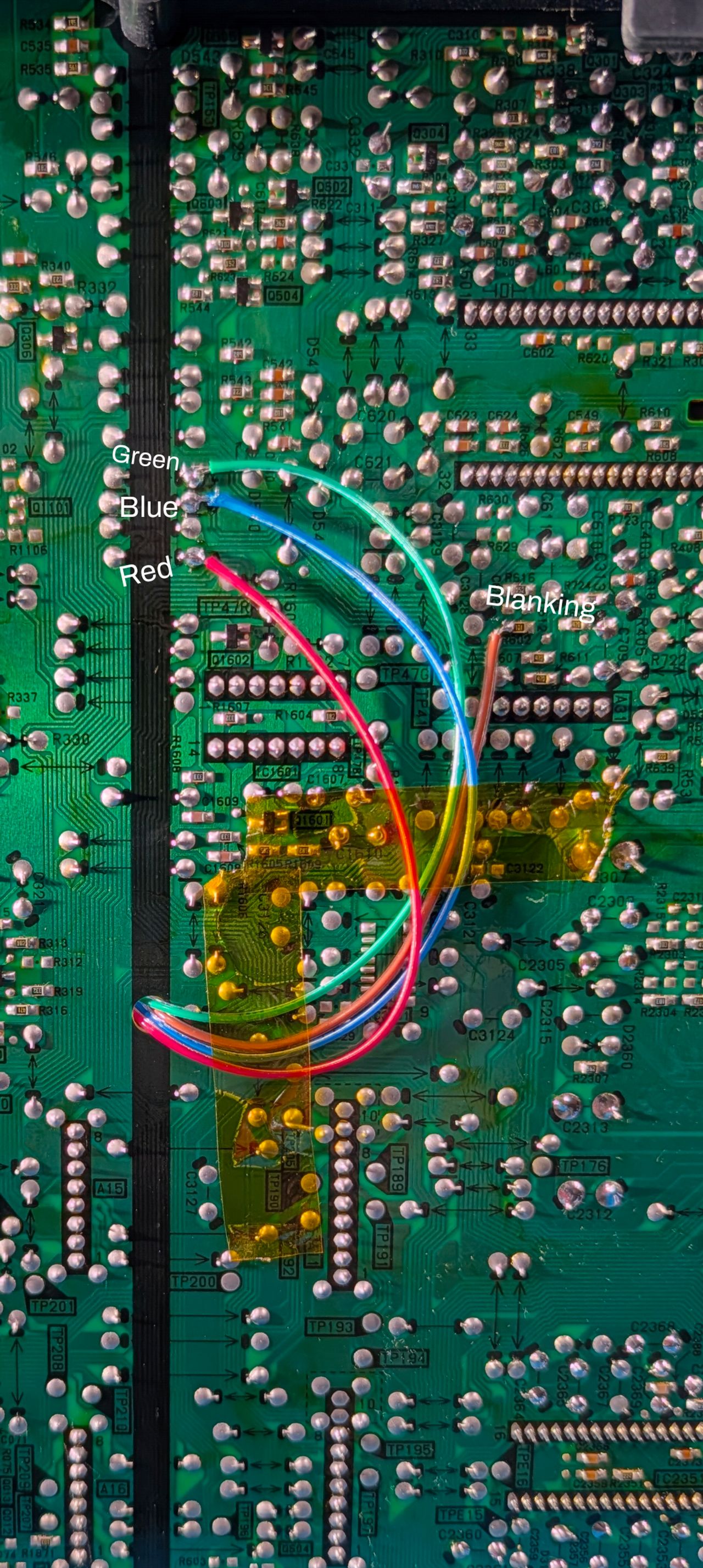
Bottom of the A-Board with connection points labeled for R,G,B, and Blanking
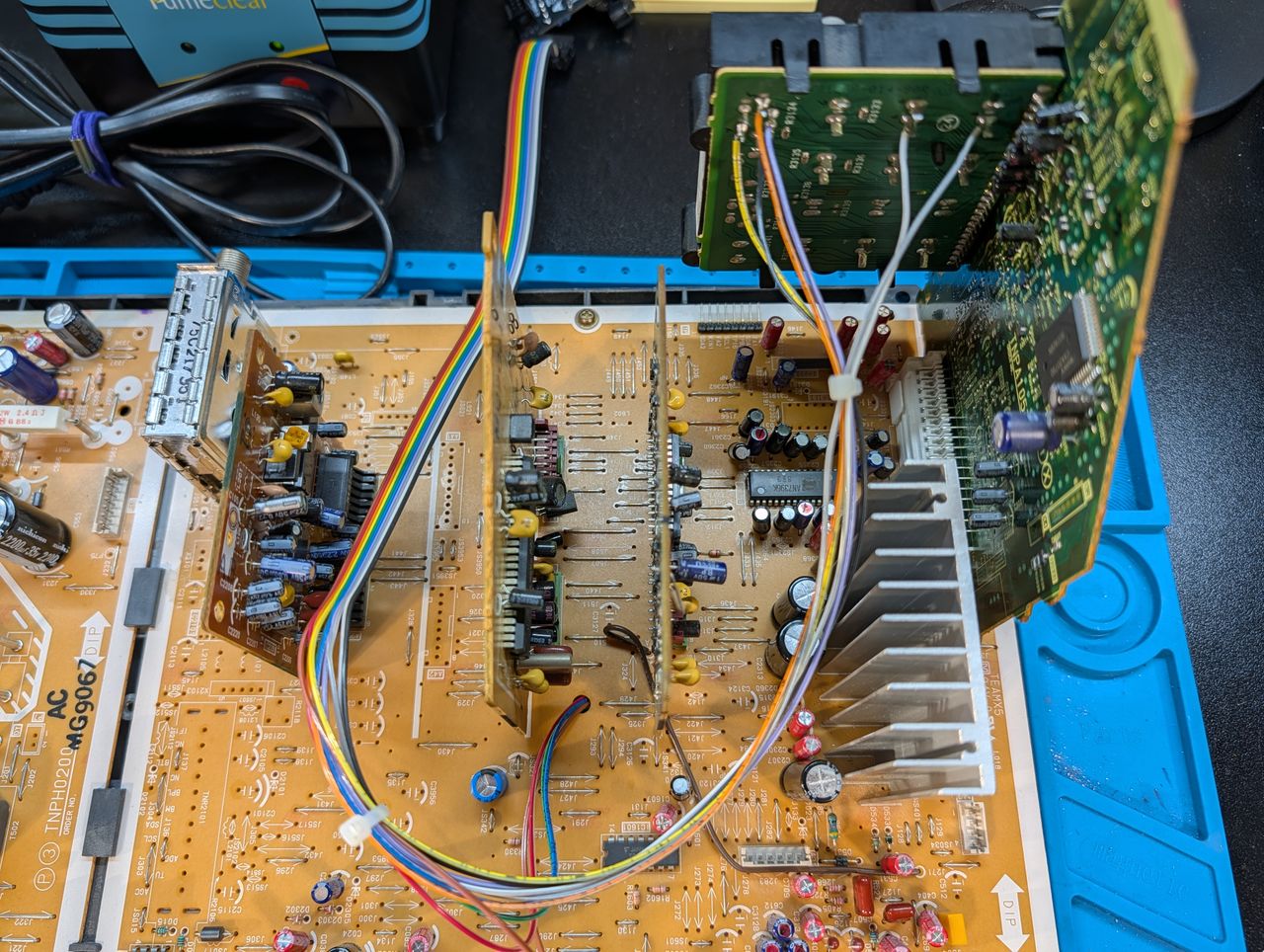
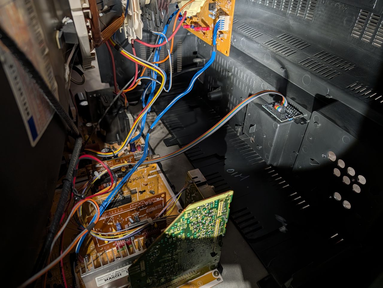
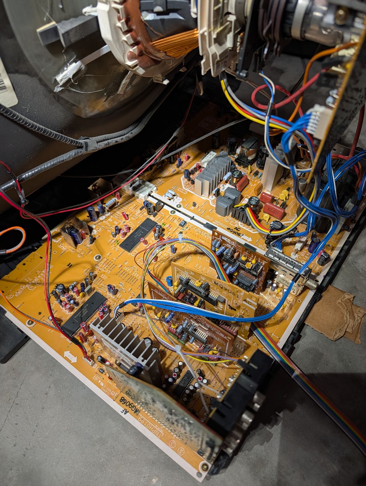
Top-down view of A-Board and wire routing
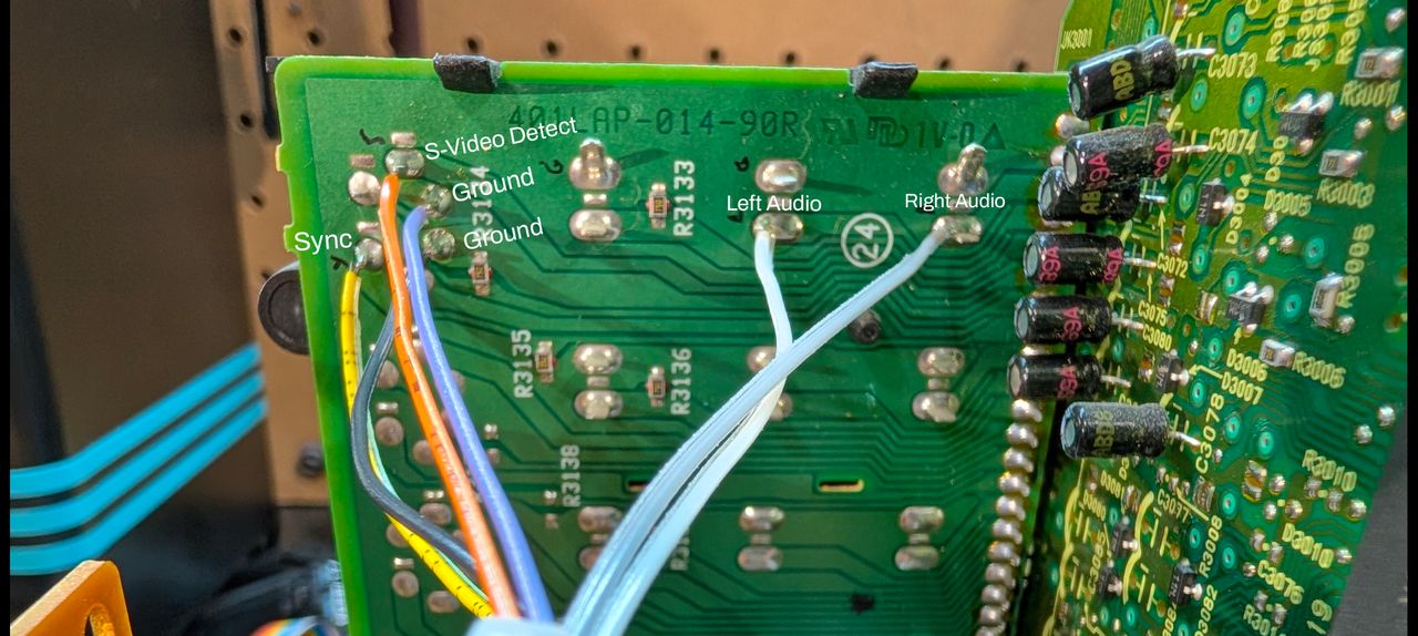
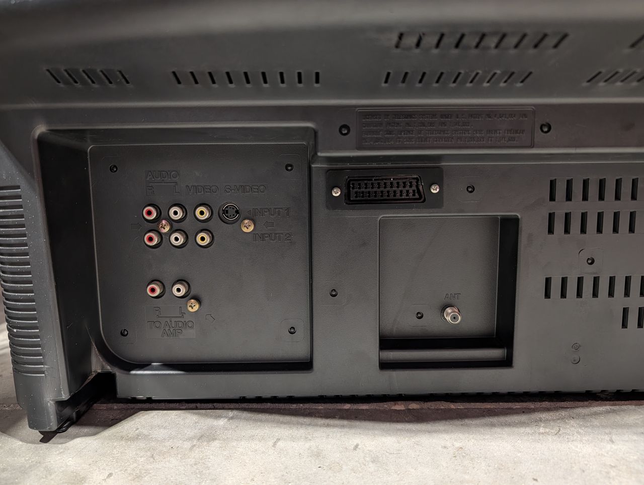
Labeled locations for all connections on the back of the input board
Top-down view of A-Board and wire routing
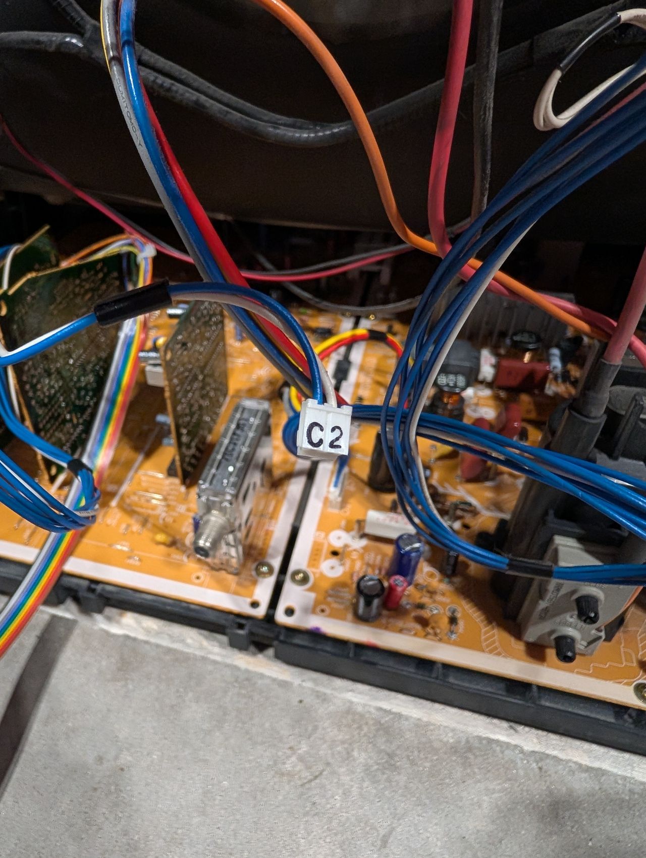
Disconnect cabled labeled C2 to disable Velocity Modulation
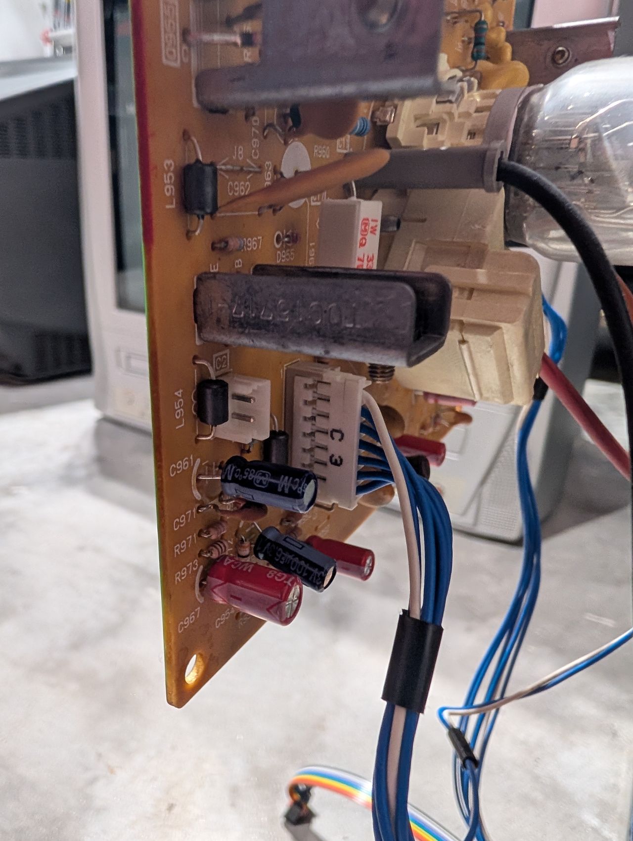
Additional image of C2 Velocity modulation pin header
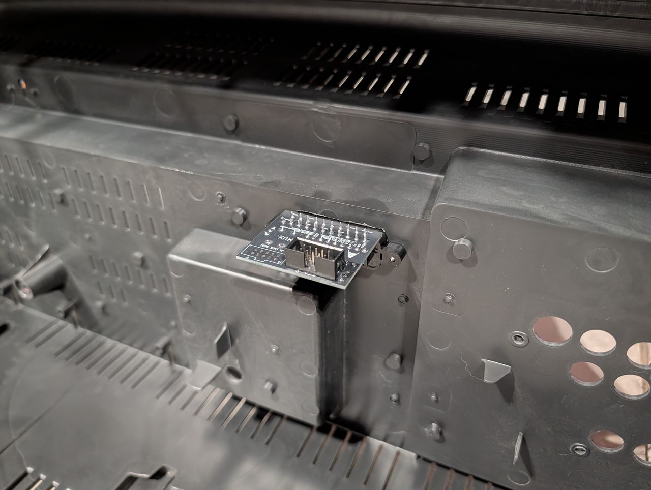
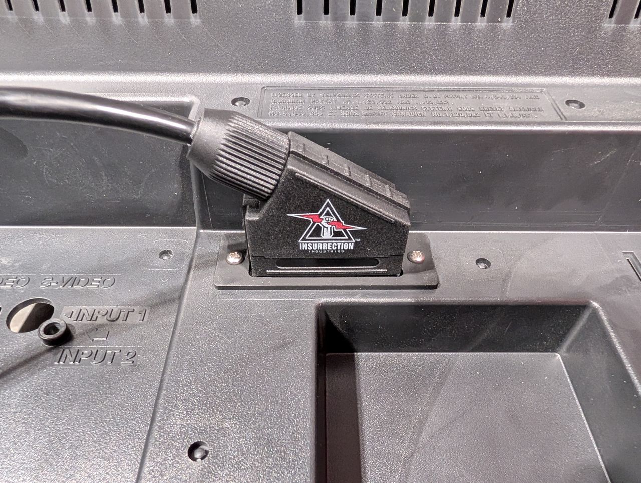
Inside shell RGB mux board mount
Location of Scart port installation