Philips 13PT30
Philips 13PT30 CRT RGB mod
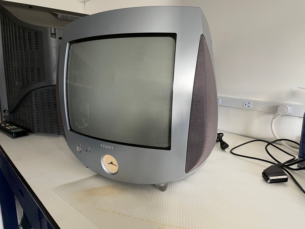
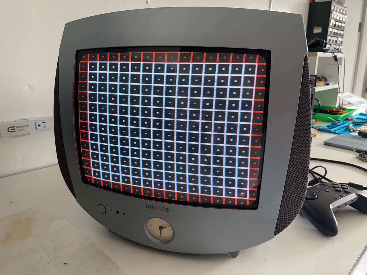
13" curved screen TV from Philips, with a peculiar analog clock in the front.
View full CRT details and more mod examples →
Contributors
Thank you to everyone who contributed to this guide:
- Davide Bacchet's Sector — photos and documentation
CRT safety
Caution
You can die doing this! So read carefully! CRT TV is not a toy. Do not open a CRT TV. If you don't have any prior knowledge about handling high voltage devices, this guide is not for you. CRT TV contains high enough voltage (20,000+ V) and current to be deadly, even when it is turned off.
Plan of attack
Manuals and Datasheets
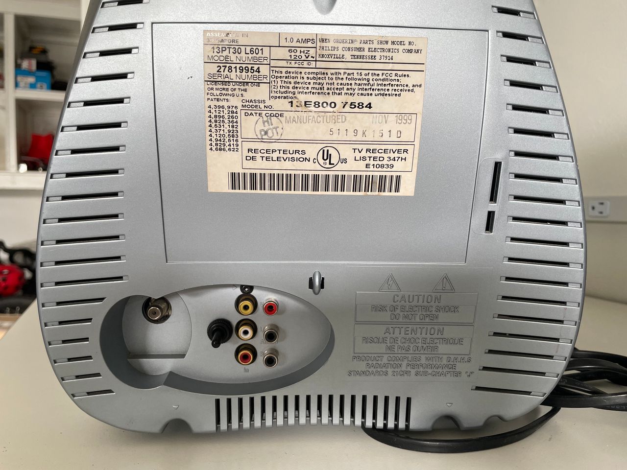
Specs
- Manufactured: Singapore (1999)
- Format: NTSC
- Chassis: 13E800
- Jungle Chip: TDA8846
- OSD Chip: SAA5565PS
- Screen Size: 13"
- Inputs: Composite, RF
Pictures
Photos by Davide Bacchet's Sector

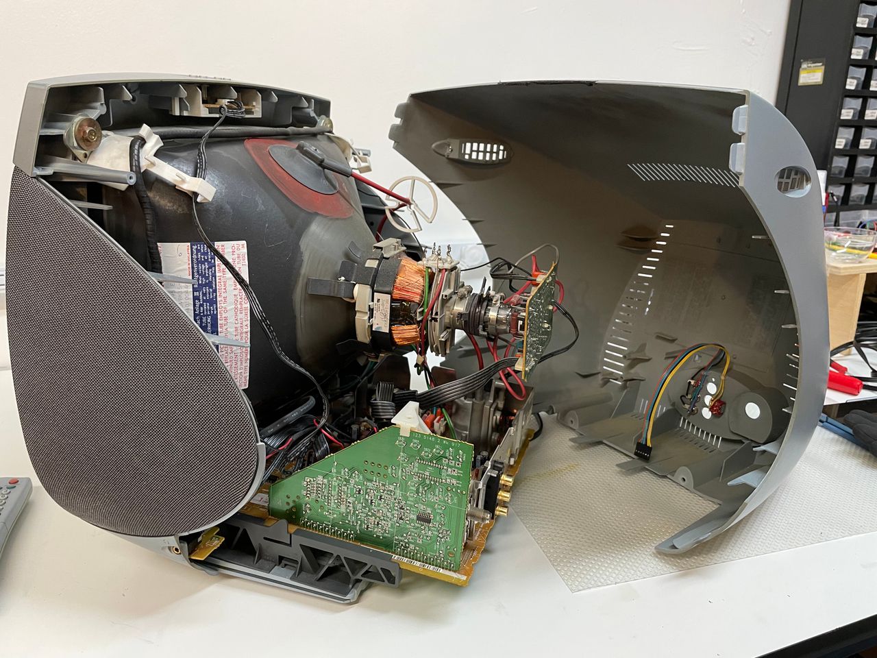
RGB Mod
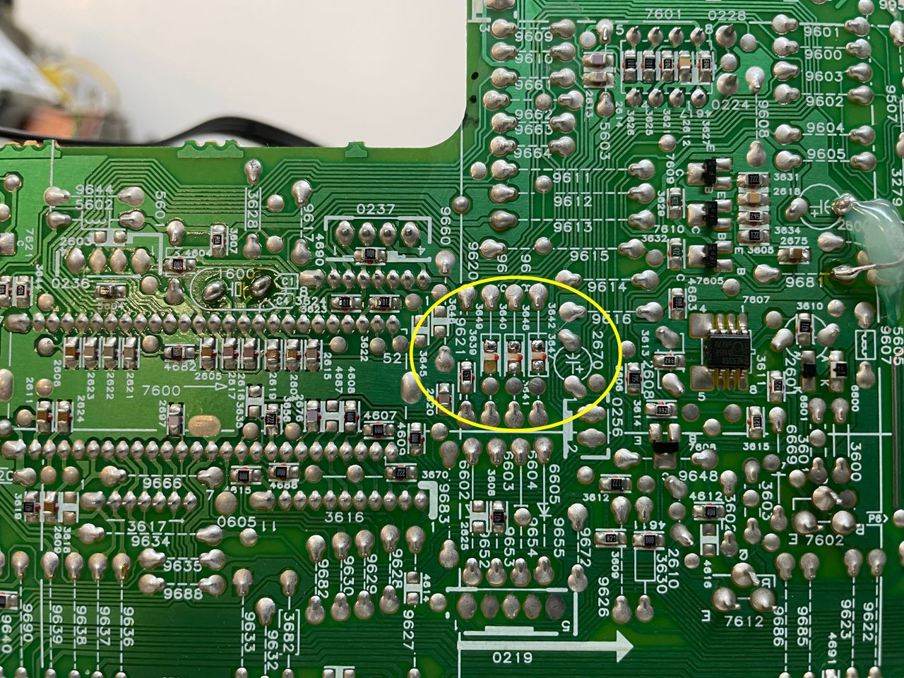
The service manual is very difficult to read, but tracing back the RGB input pins in the TDA-8846 (pin 23,24,25) you can find the grounding resistors 3647, 3648, 3649, that are 82 Ohm SMD resistors. Remove them as shown in the above picture
Since 82 Ohm is very close to the standard 75 Ohm termination value in the external RGB lines, there is no need to add any inline resistors in the mux board (see how the inline resistors have been replaced by jumper wires in the small mux board).
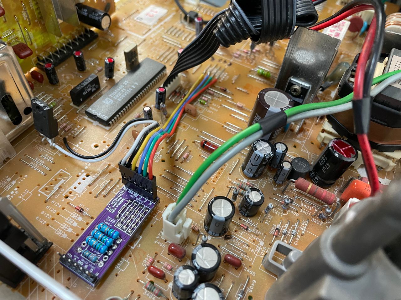
In the picture above you can also see how the external RGB lines have been terminated with a starndard 75 Ohm resistors.
The blanking signal on this chroma is a little delicate, as it only accept a very limited range of voltages around 1.5V: too low and it will not trigger and too high it will produce a black screen. Depending on where you get your source voltage from you might need to experiment with an inlne resistor, or a small pot. In the picture above we got 5V from a voltage regulator.
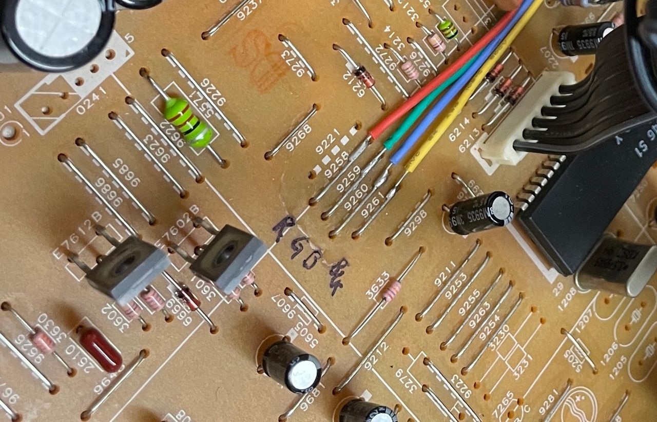
The signals can be injected to the jumpers 9258 (R), 9259 (G), 9260 (B) and 9261 (Blank) as shown in the above picture
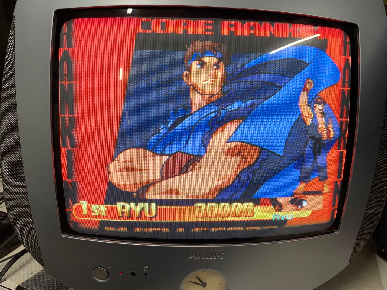
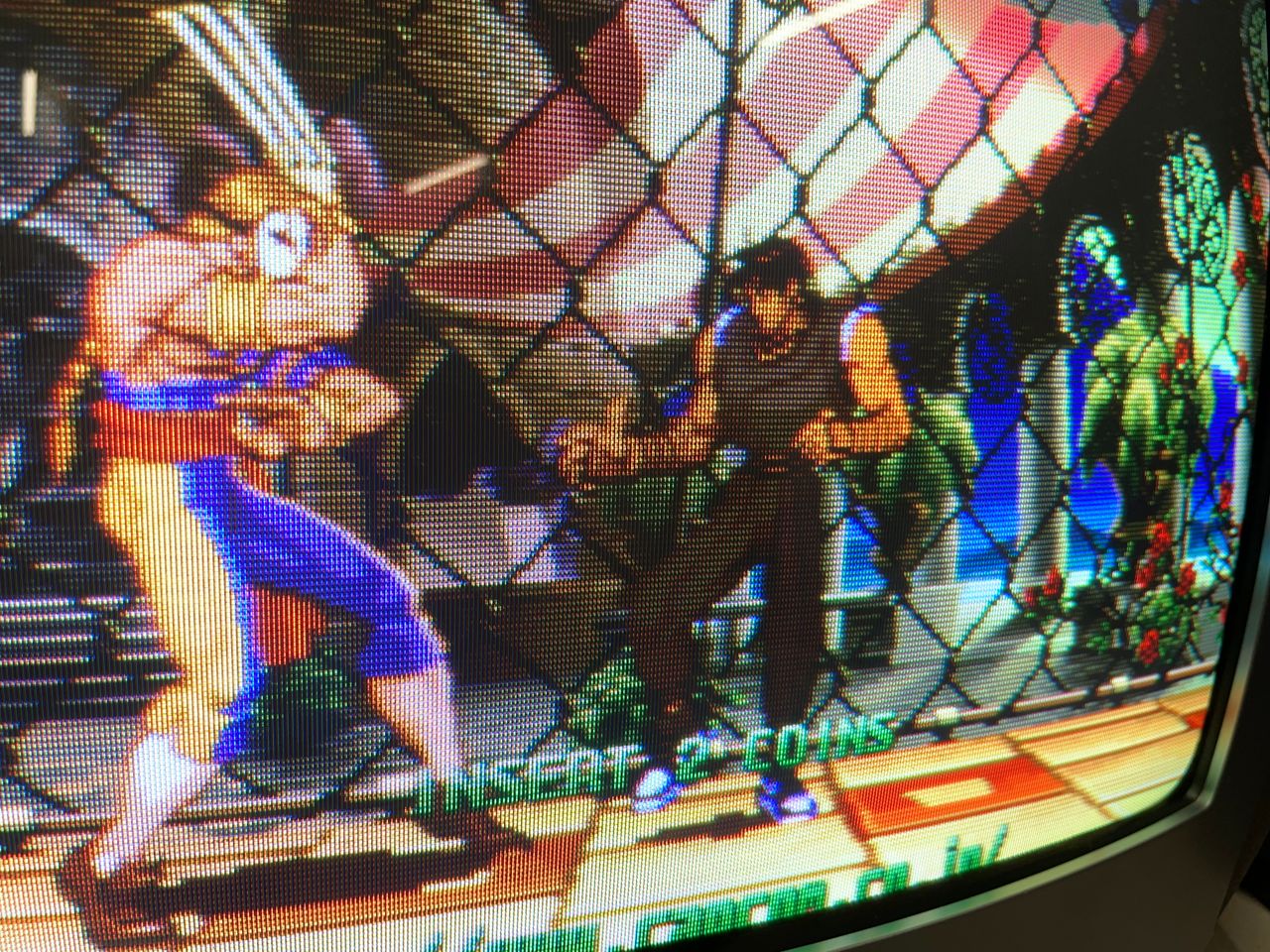
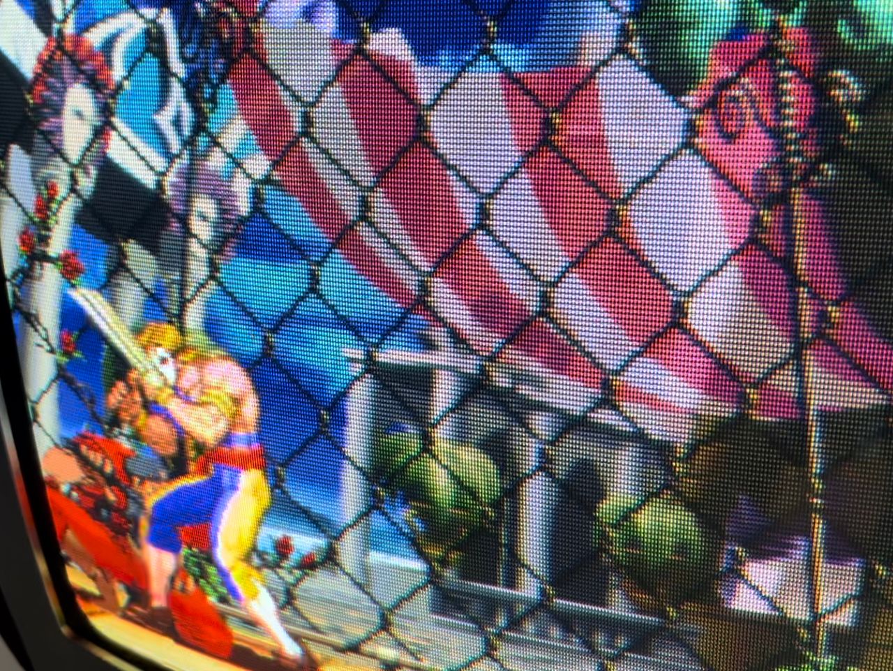
The result is a very nice and sharp image!
Reference Photos