You can die doing this! So read carefully! CRT TV is not a toy. Do not open a CRT TV. If you don't have any prior knowledge about handling high voltage devices, this guide is not for you. CRT TV contains high enough voltage (20,000+ V) and current to be deadly, even when it is turned off.
Prepare the mux diagram. If you are building your own circuit, this diagram should help.
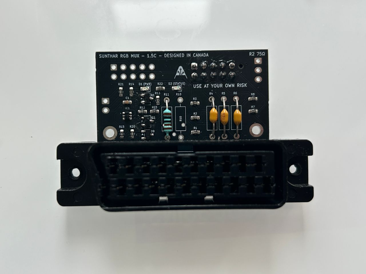
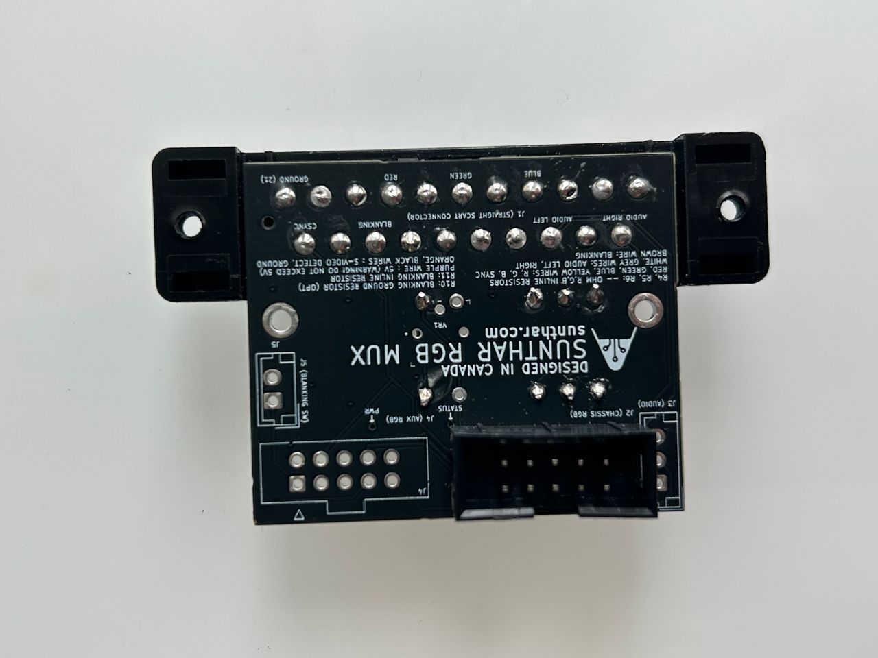
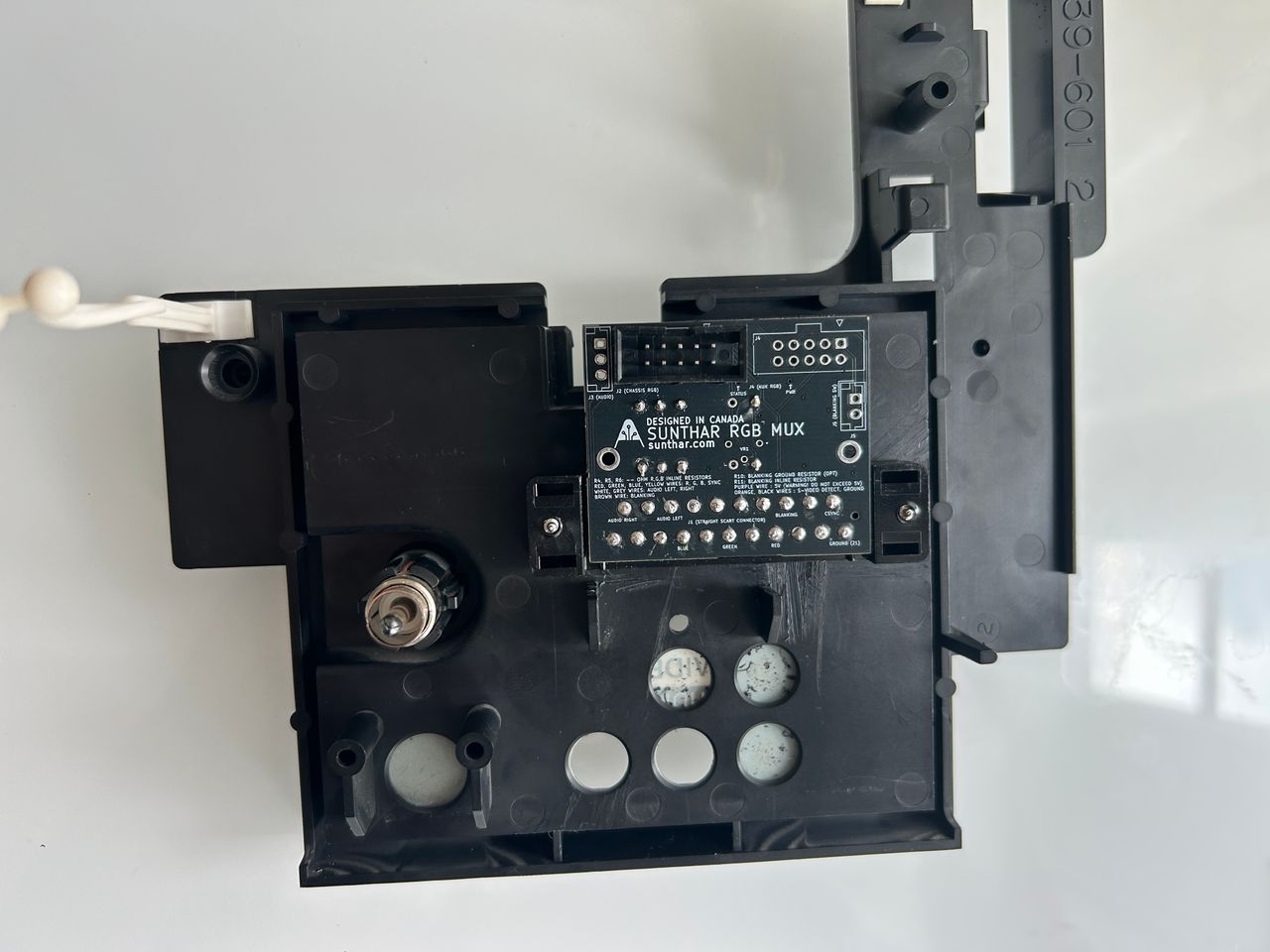
This mod uses the RGB mux board. This is optional, but will make your mod easier and stable. You can also create the circuit presented in the schematics above without the board. Please also checkout the mux calculatoropen in new window to play with your own values.
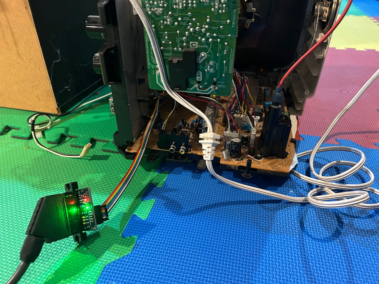
Used the latest 1.5C board to modify this set. Worked amazingly well. Tested with 3V blanking input from MisterPi and the set was able to switch.
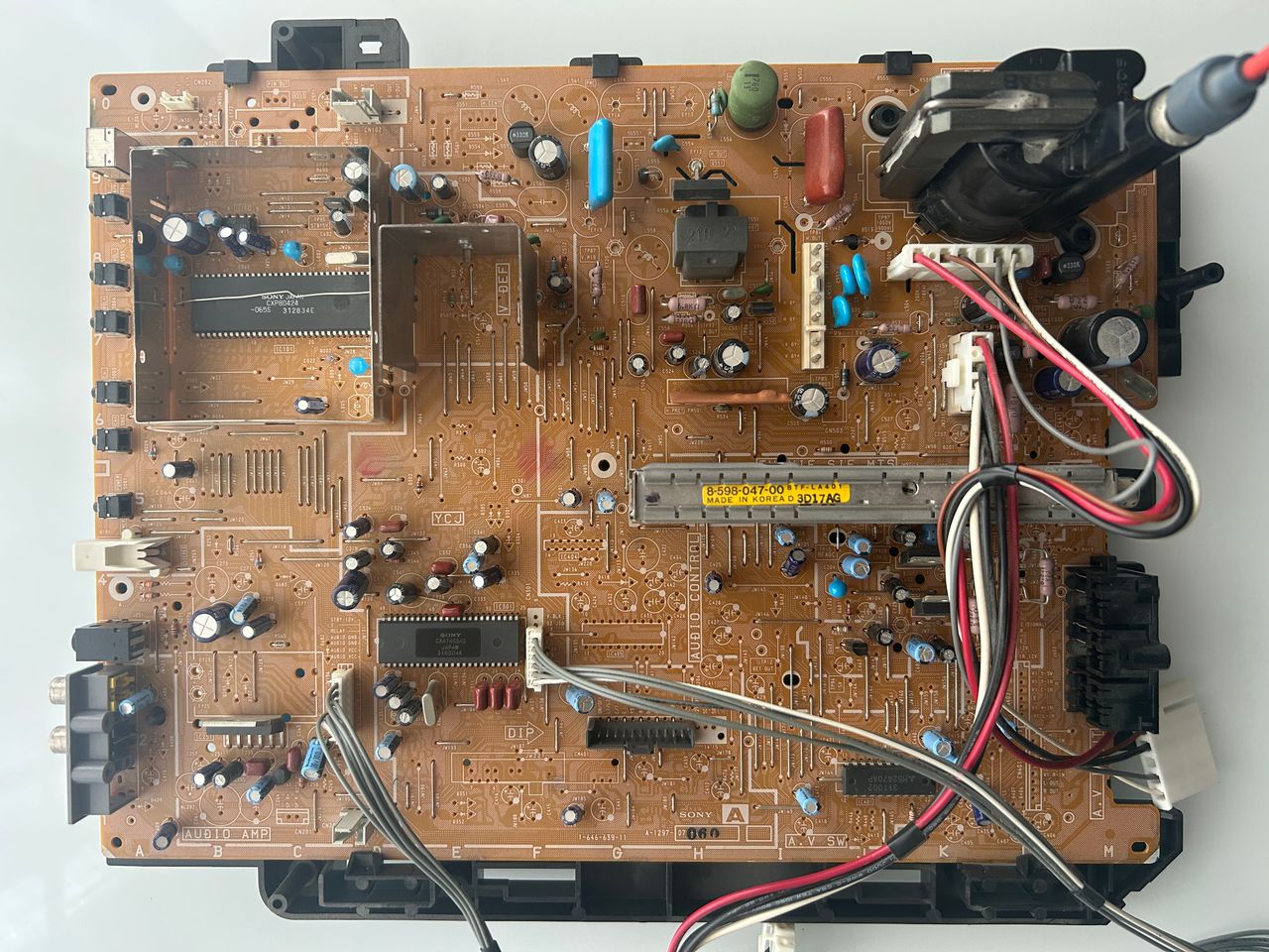
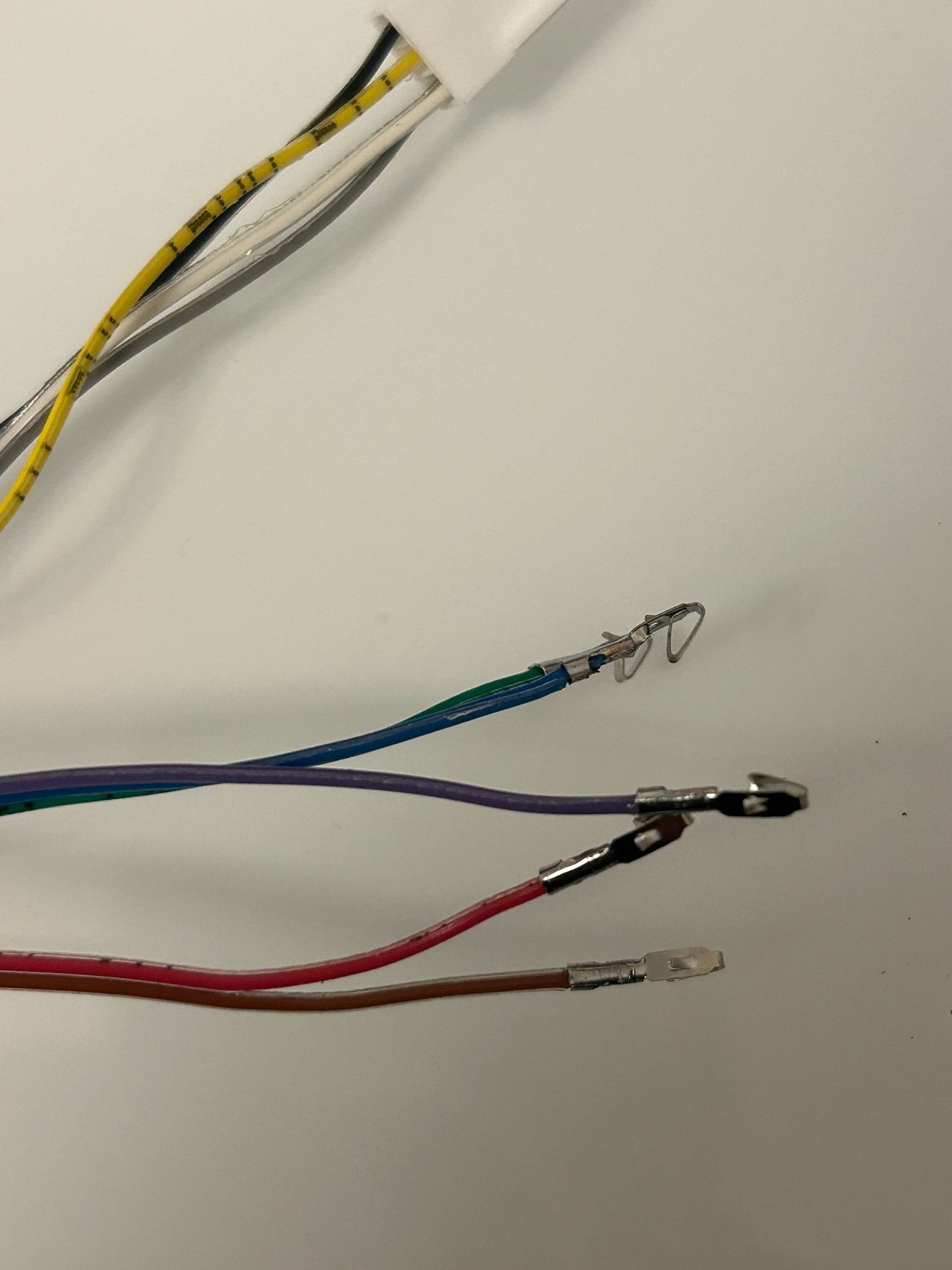
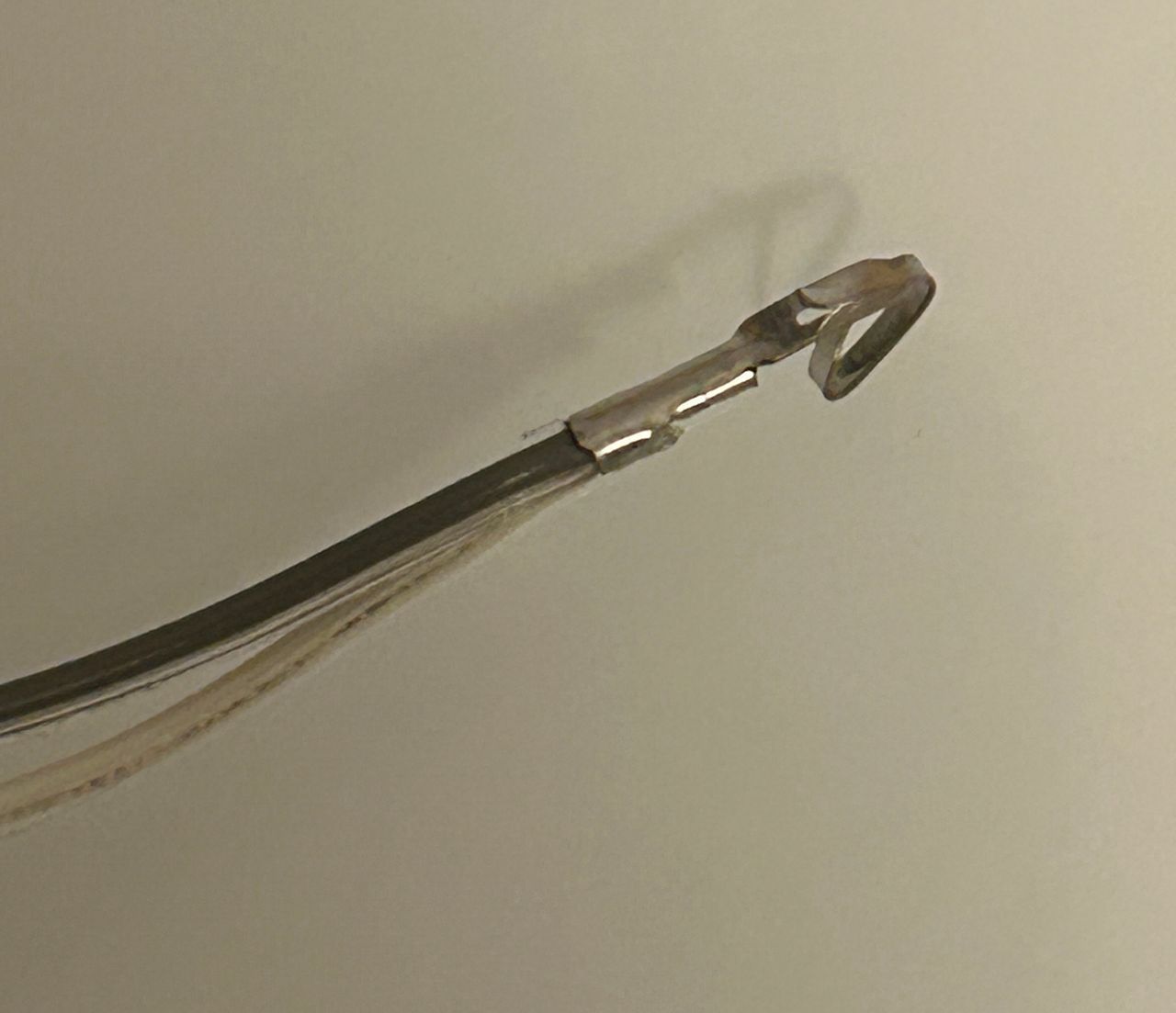
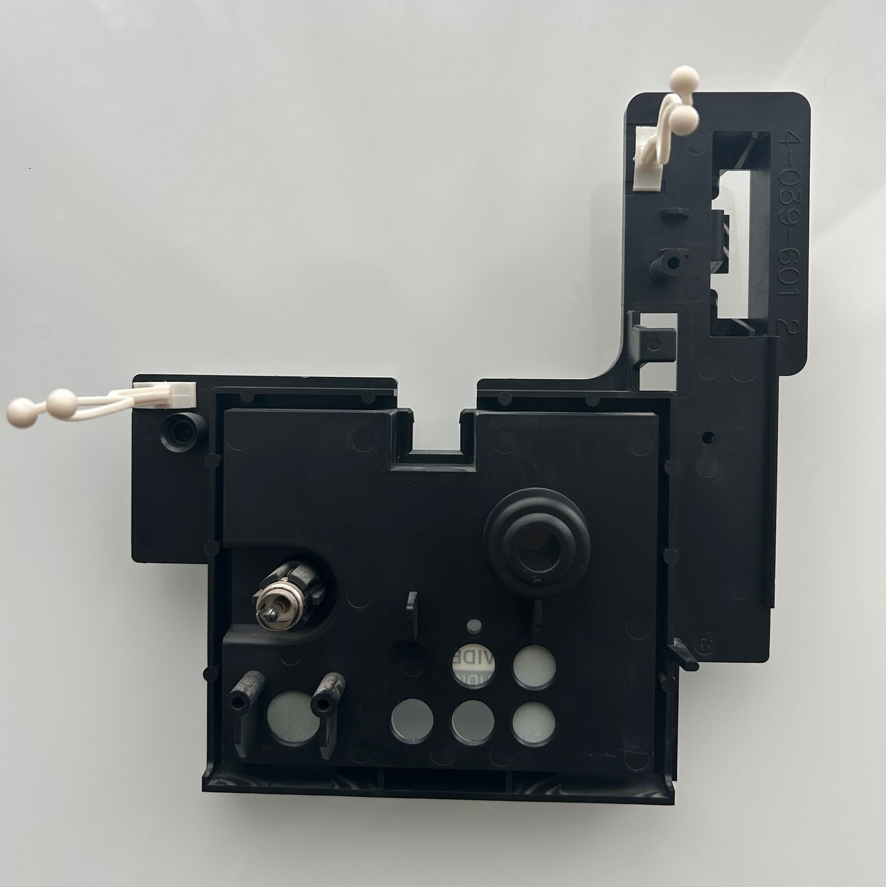
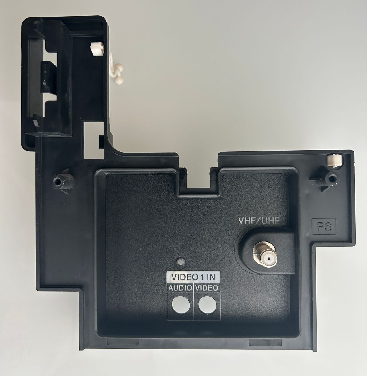
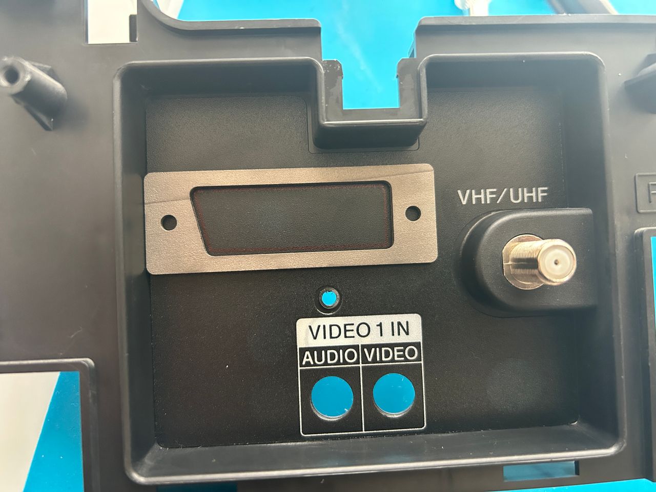
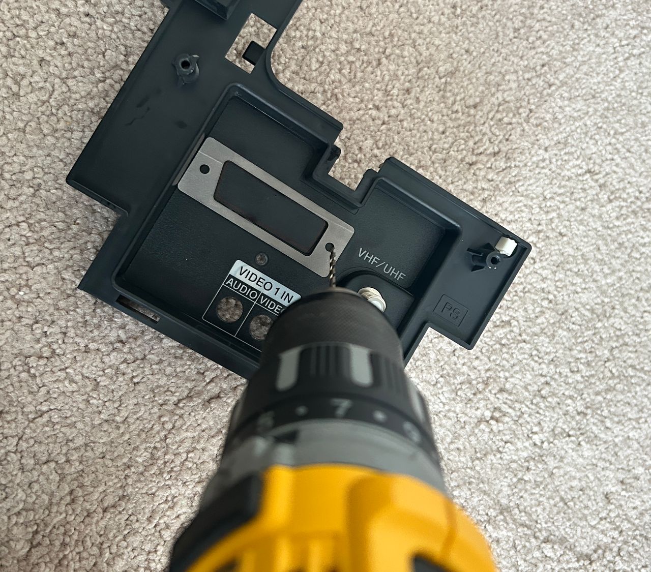
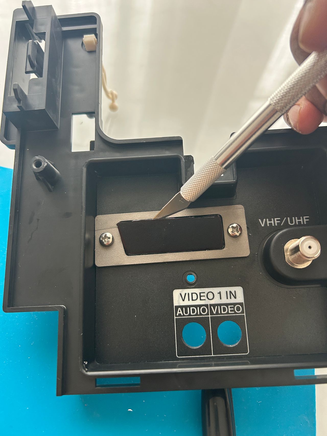
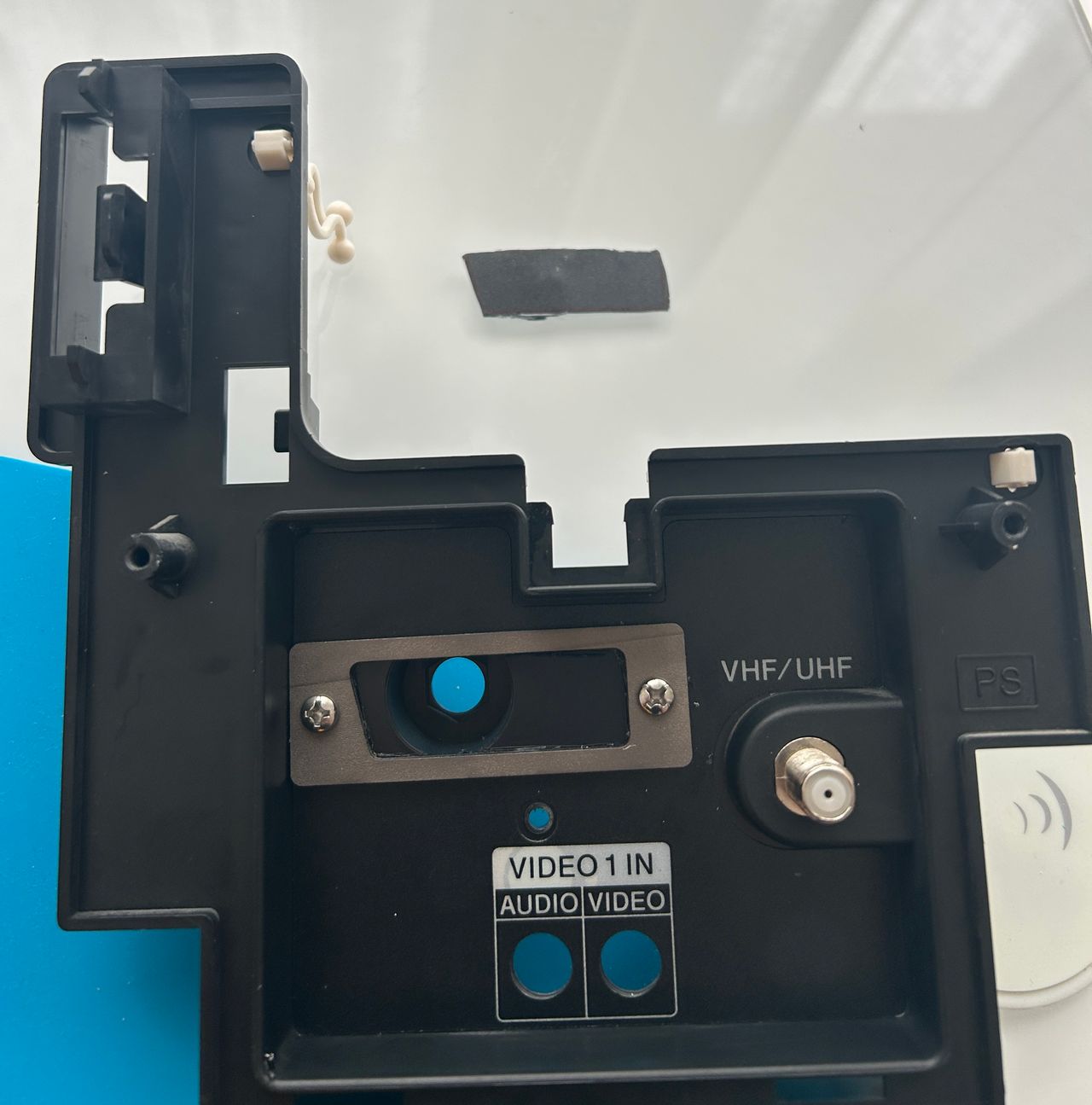
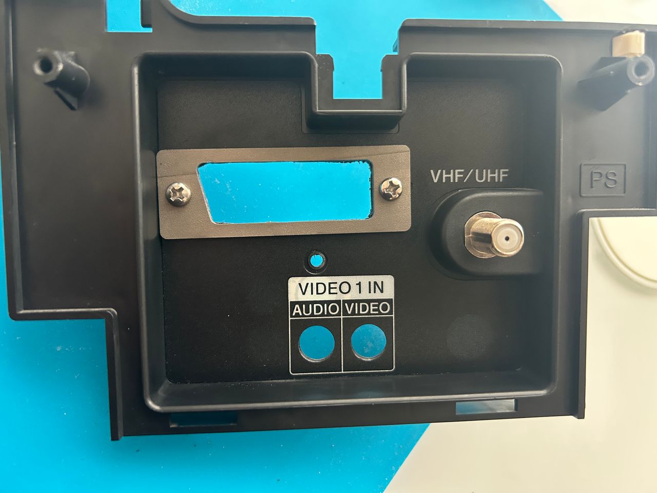
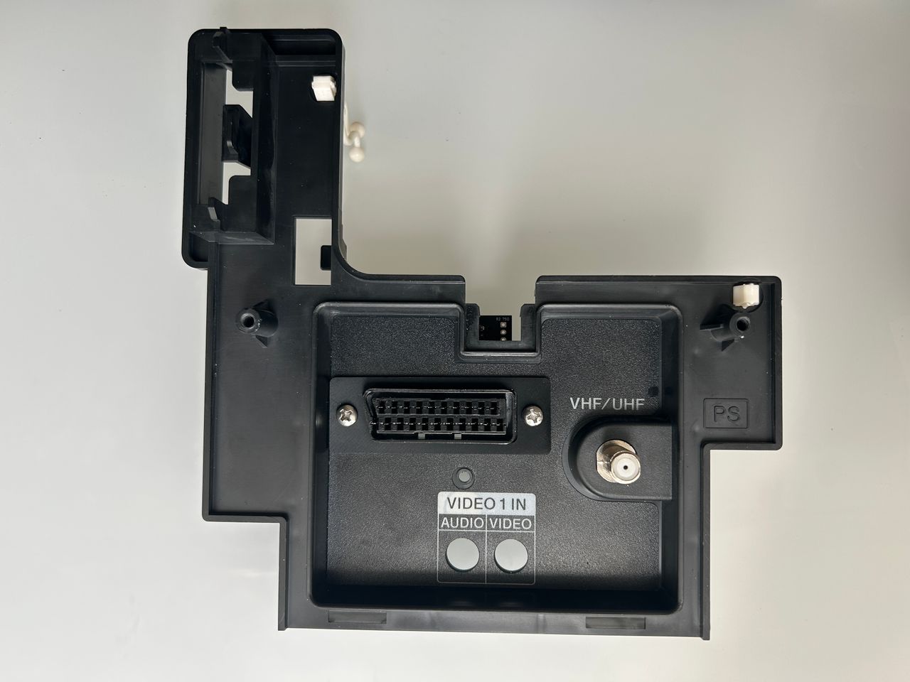
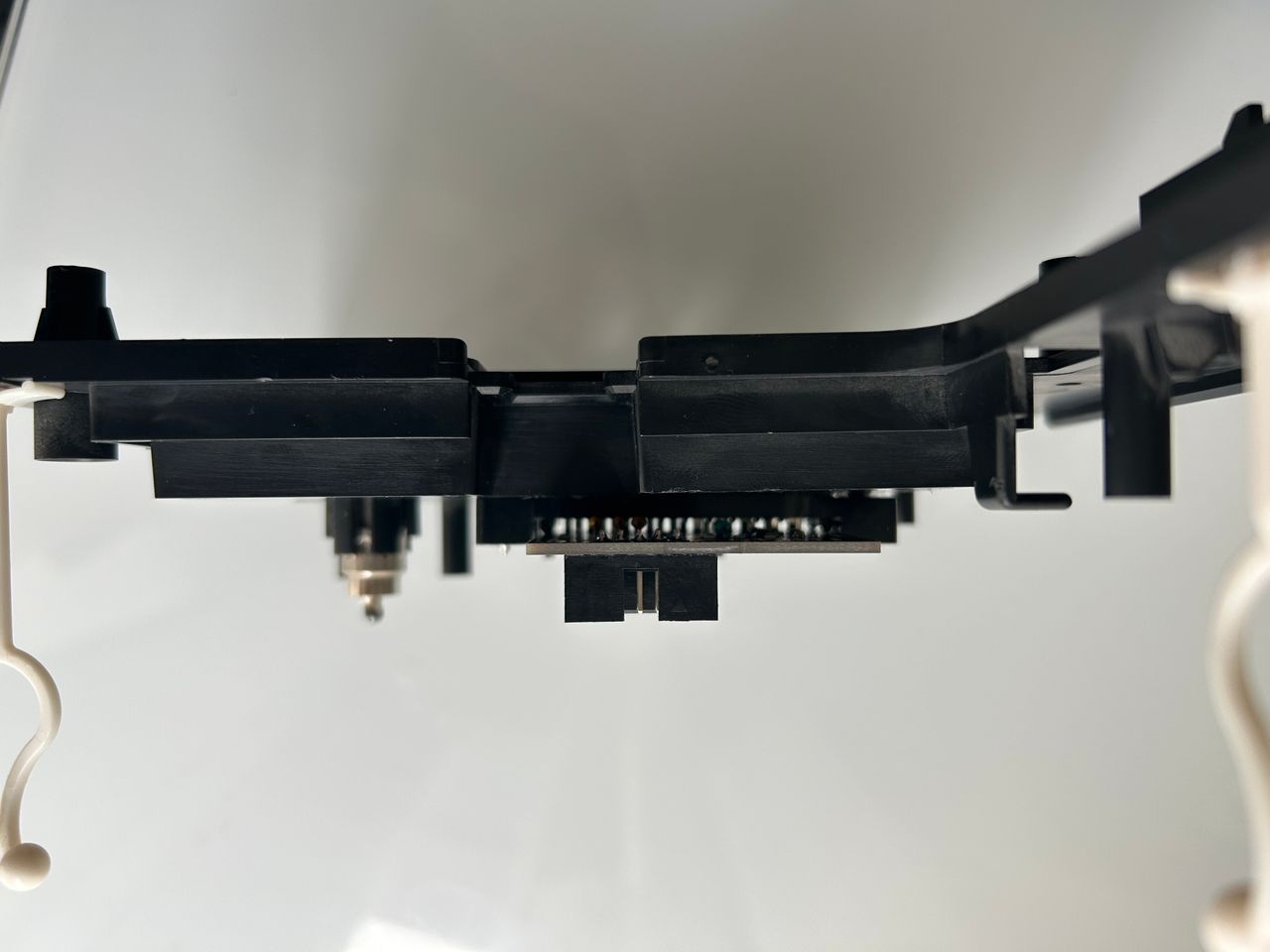
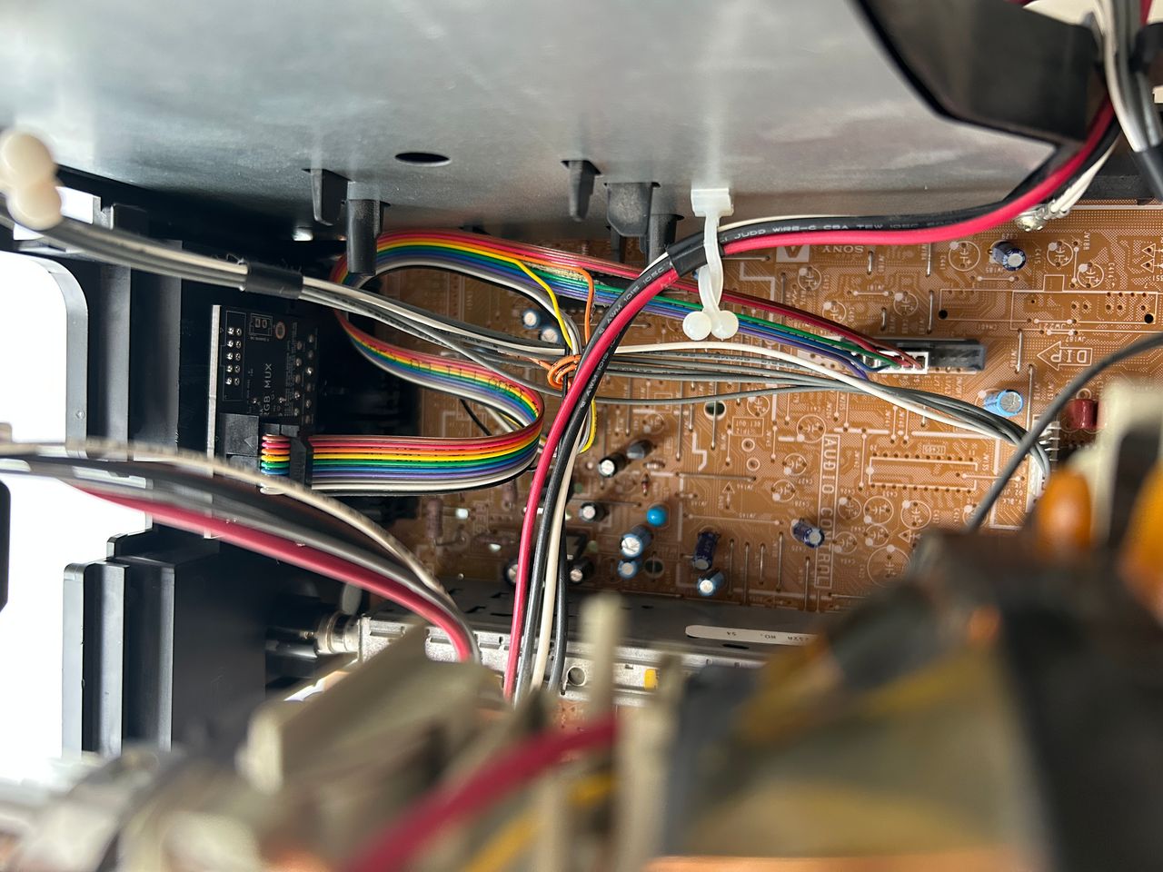
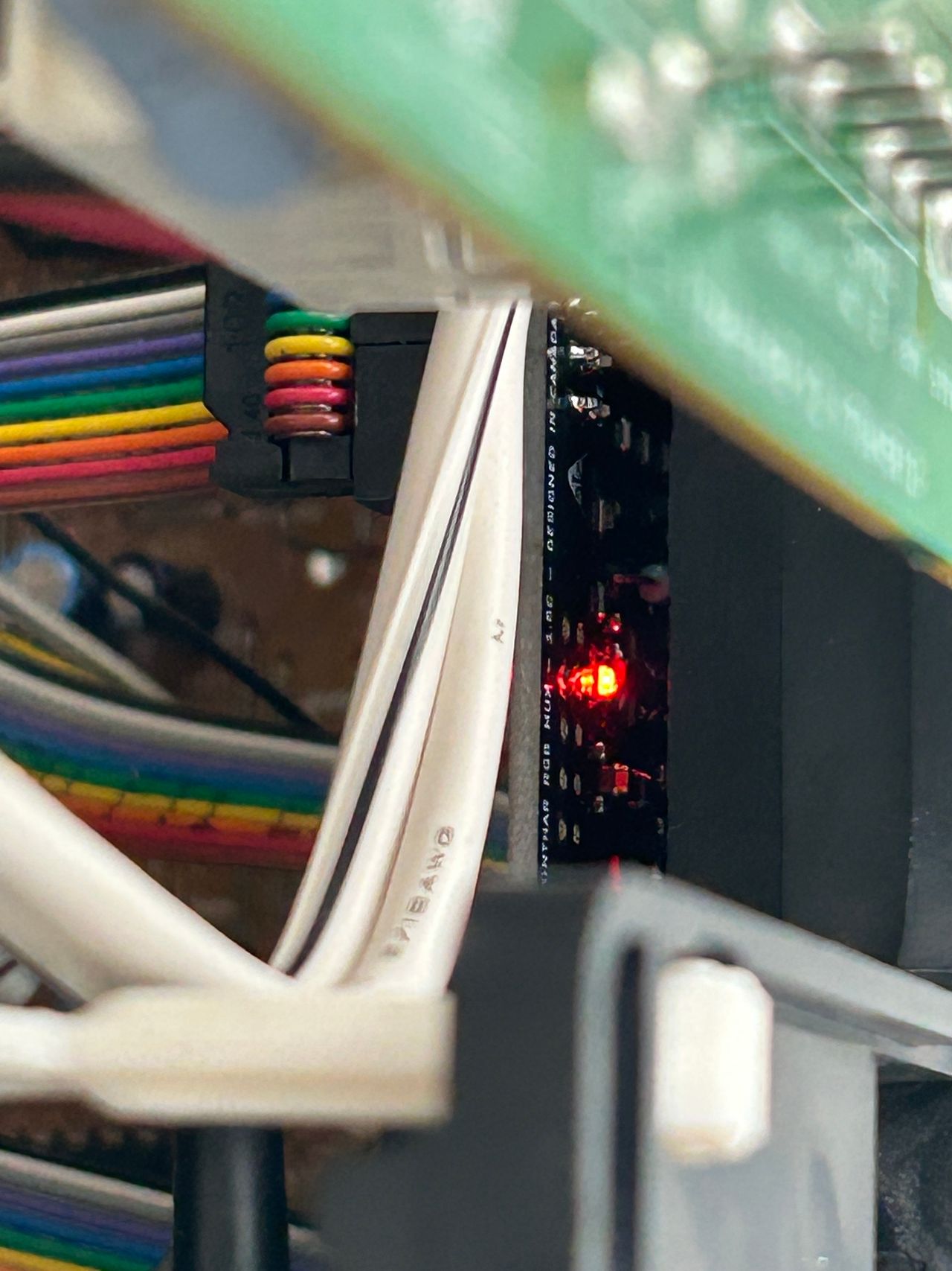
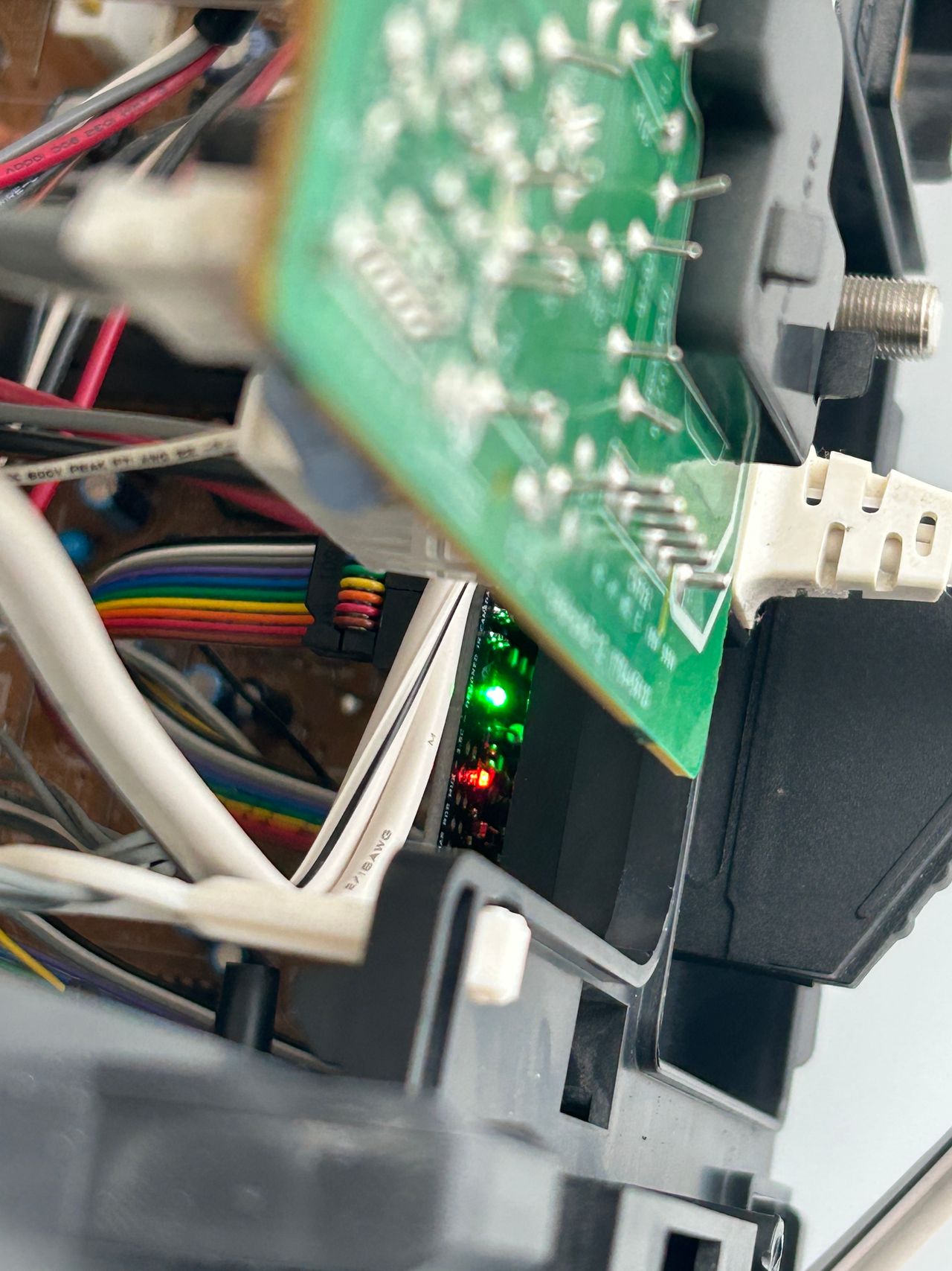
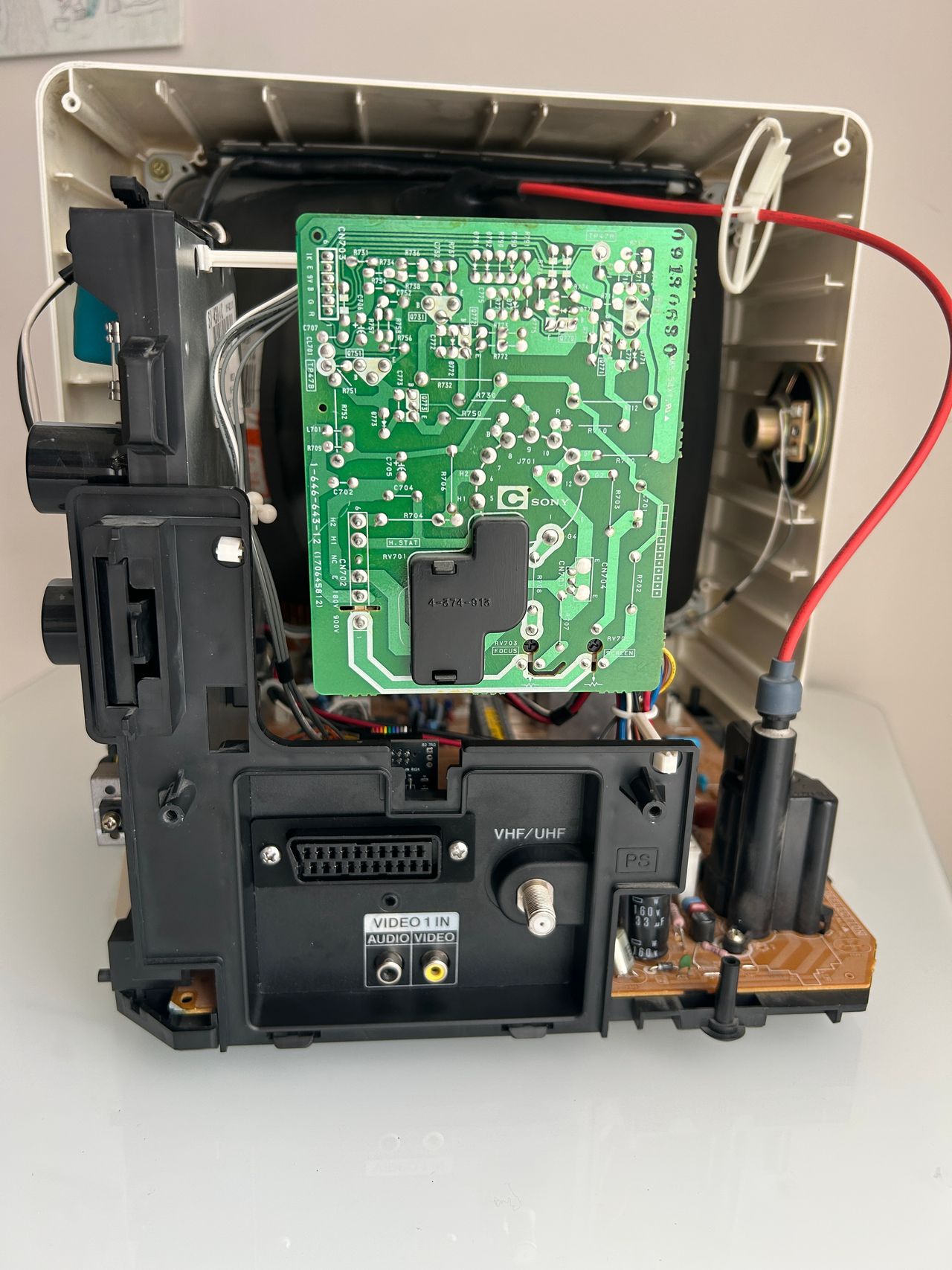
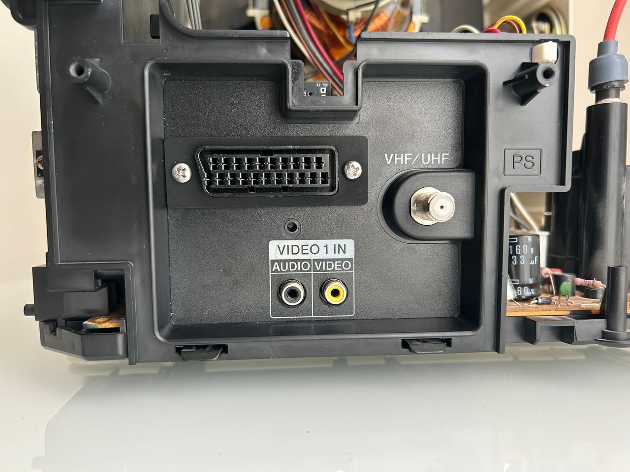
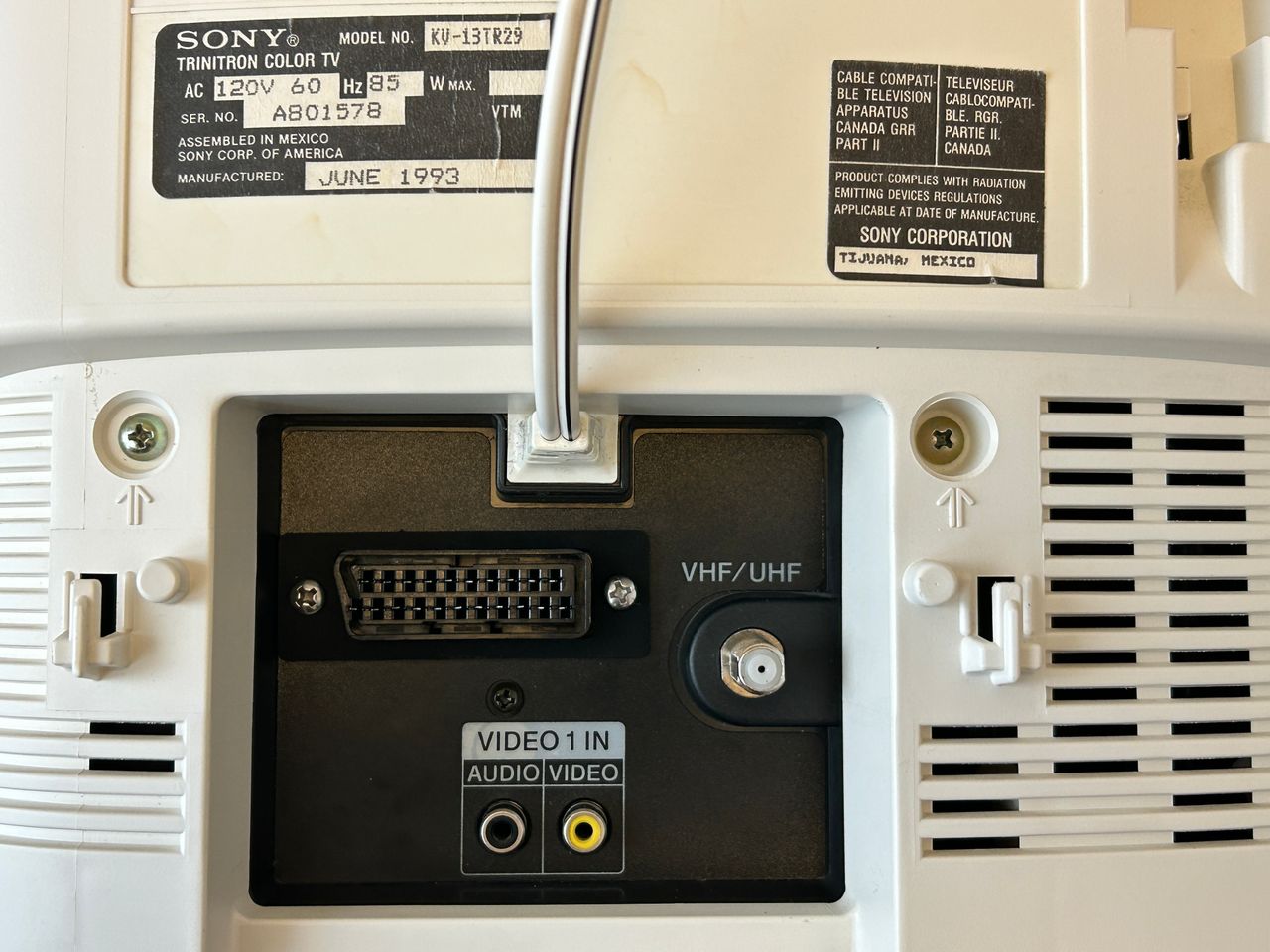
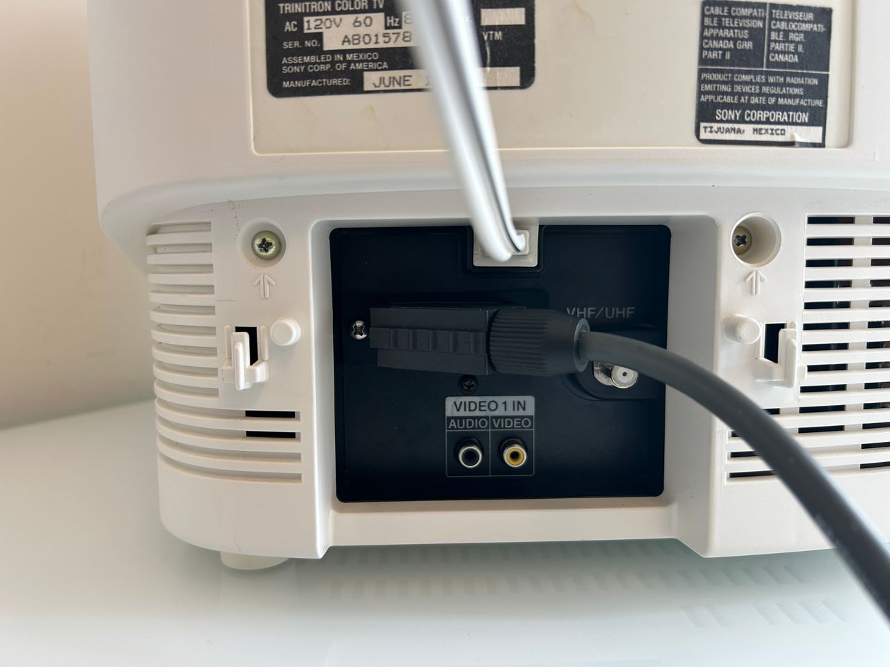
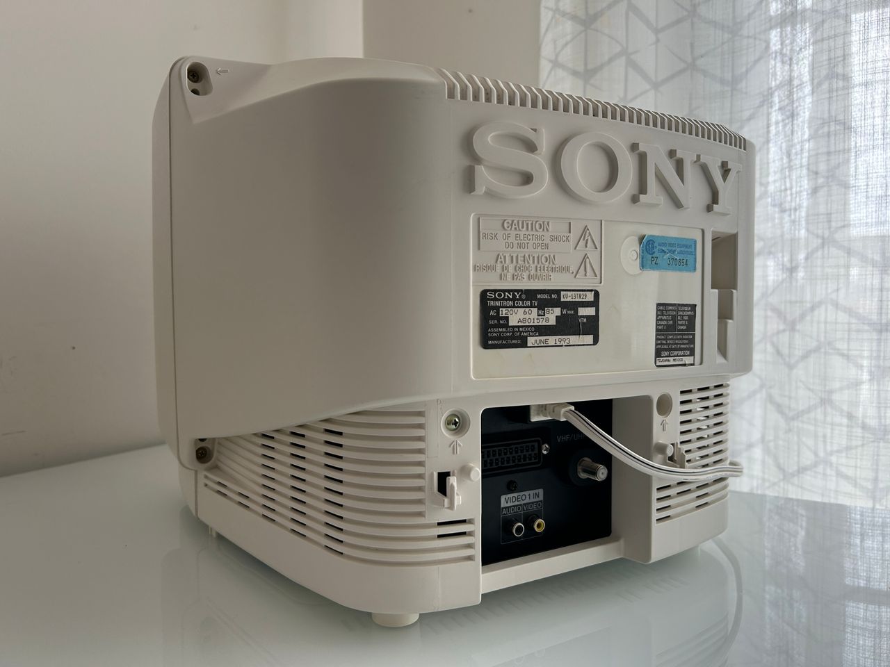
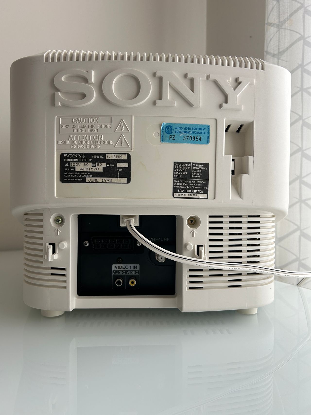
6 screws to remove the back cover of the CRT. One black screw to remove the A/V panel. Wires crimped properly Purple wire here is for 5V. Rest is standard. This where you will inject video, audio and ground. Since this set only supports mono audio, make sure to tie both grey and white wire together. Grey and white wires crimped together. This panel is where we are going to mount the SCART cable. Planning the position of the SCART port is extremely important. There is plenty of space. Make sure to not block the VHF/UHF, Video 1 In ports from the back. Make sure power cable can still be routed. The is the position I found the best to mount the 1.5C board. If the space is even tighter you can use the 1.5C extension board. If that doesn't fit, you can use a micro adapter. There are plenty of options. For this set, having a full SCART port is possible. Next, you have to be very careful with the black sticker. If not cut properly, it leaves marks that are unpleasant. I'd say, cutting a professional SCART port to mount the SCART adapter is hardest part of the mod. So, take your time with it. I had a metal SCART template made. I used that and an xacto knife to carefully cut out the thick sticker. It wasn't perfect, but I was able to then work with the plastic. If you don't do this way, then the thick sticker can get really messy. Used a file to make this as perfect as possible. Once again the black sticker makes it really hard to work with. 1.5C mux board in action. Red light here means, you have got the power rail hooked up correctly to a 5V regulated rail Green light here means, blanking is understood by the mux board. Tested with MisterPi at 3V and 5V.
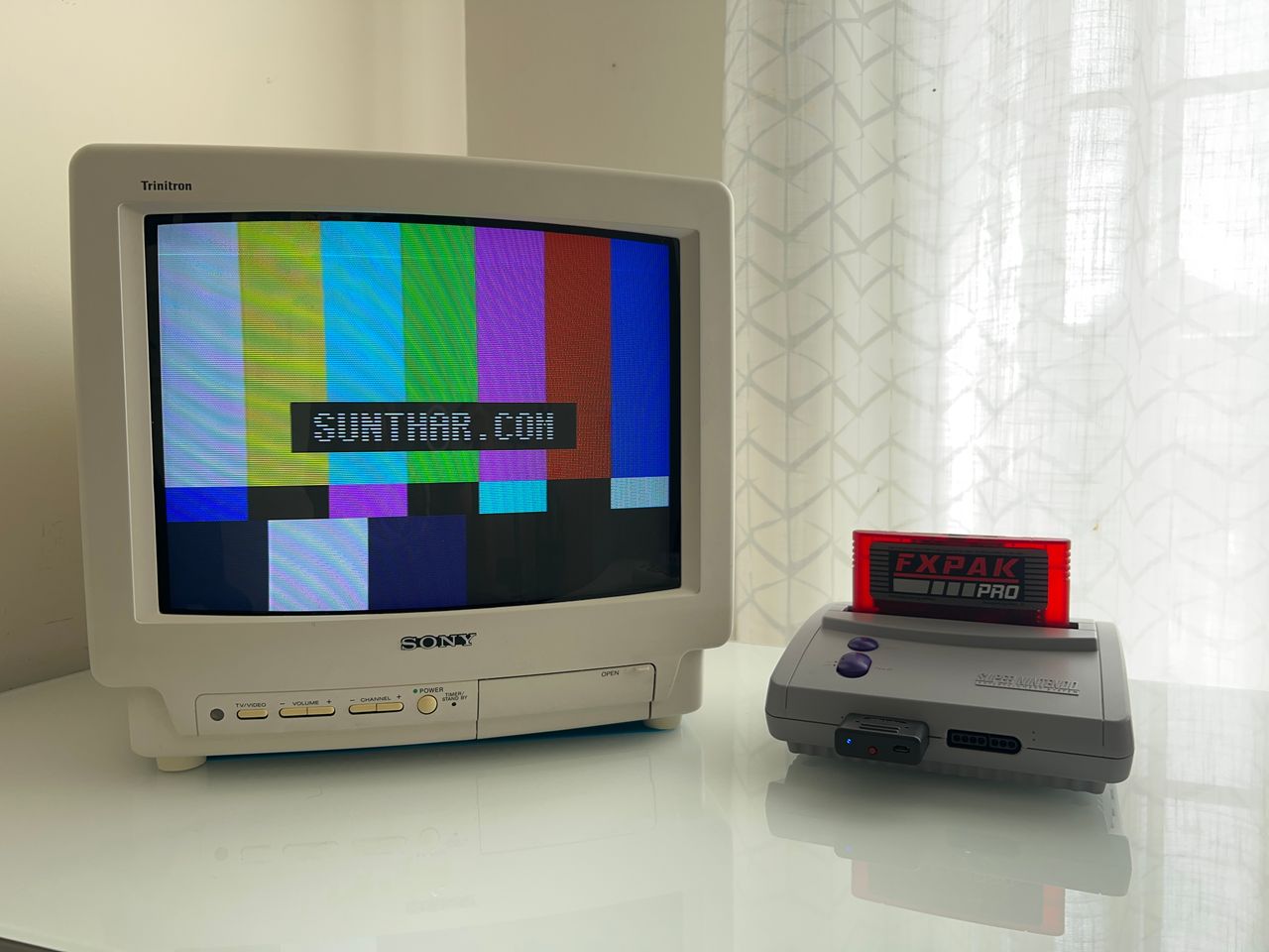
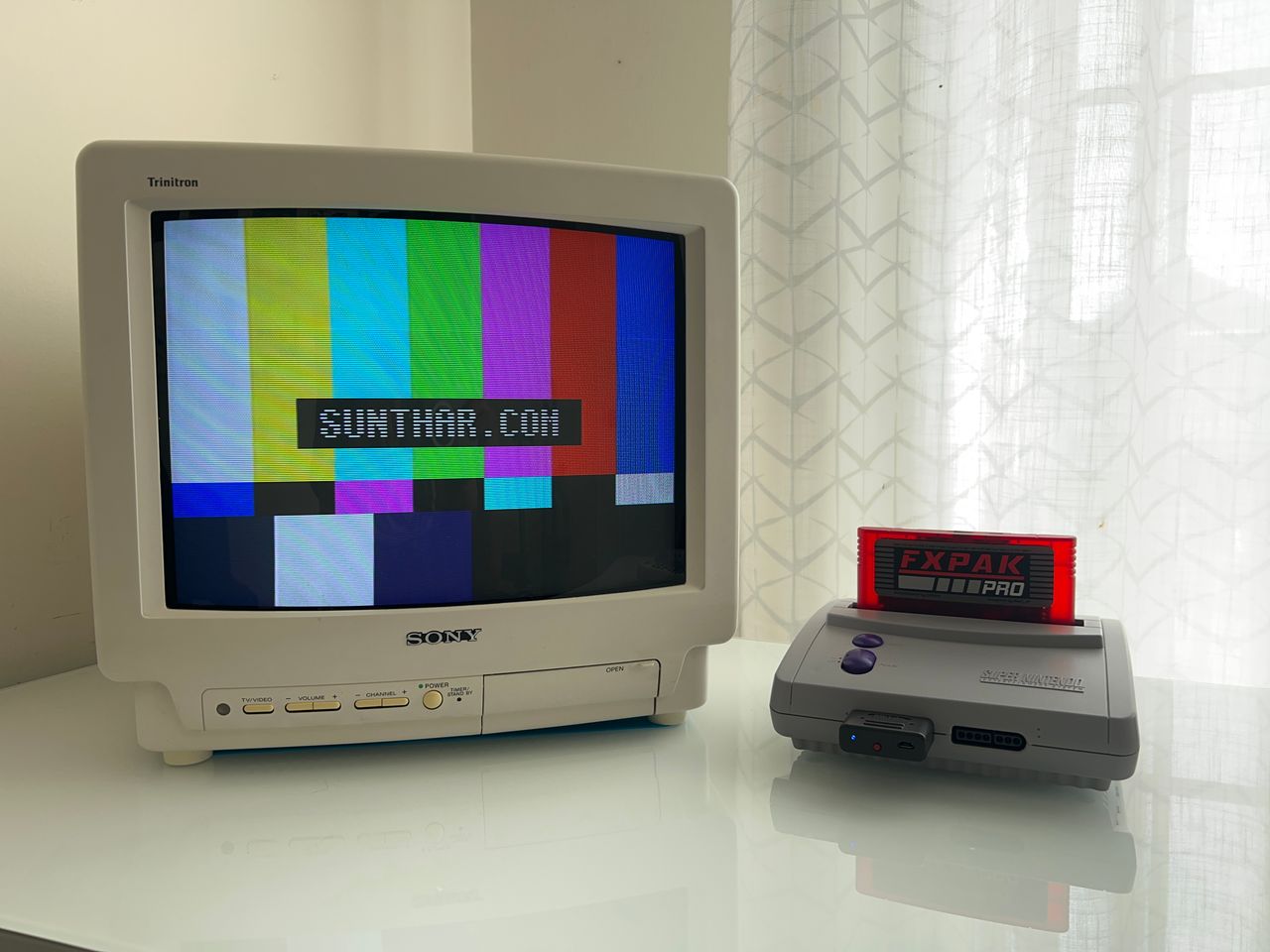
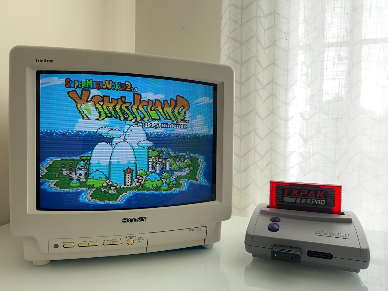
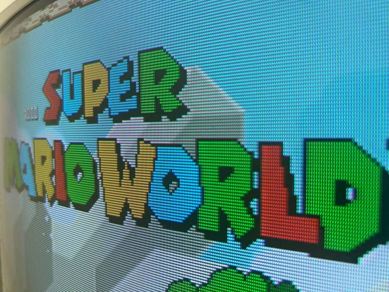
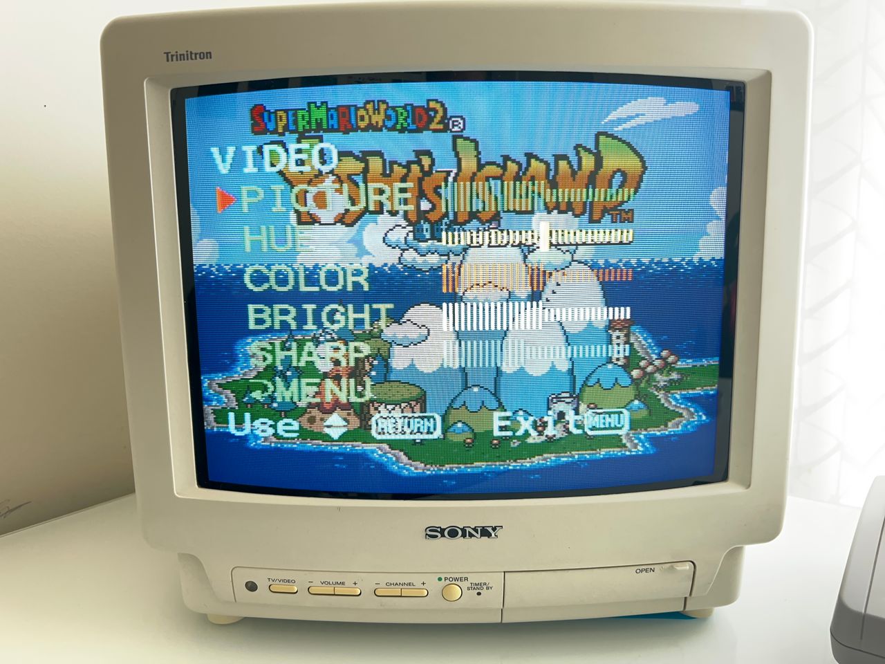
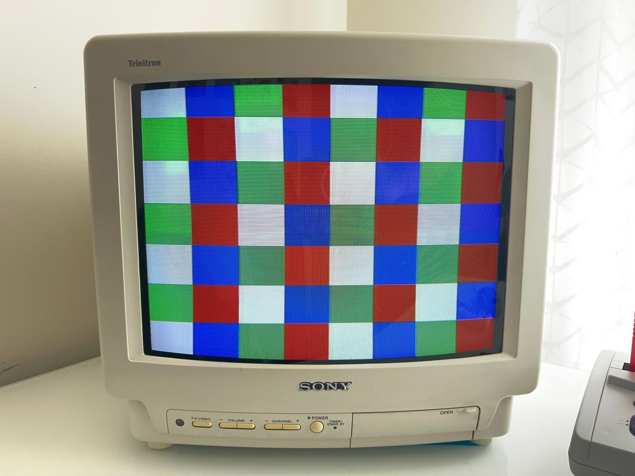
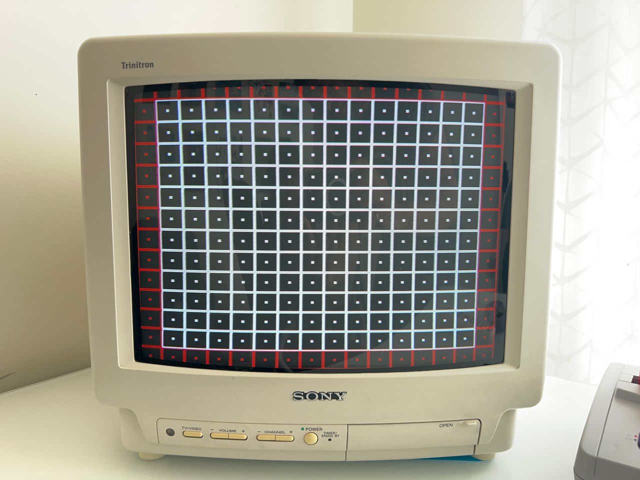
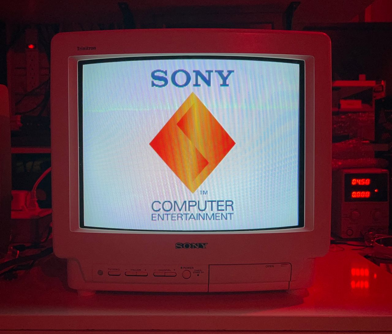
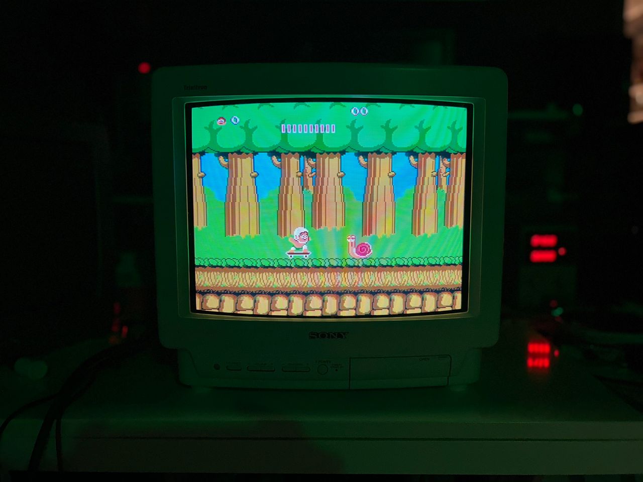
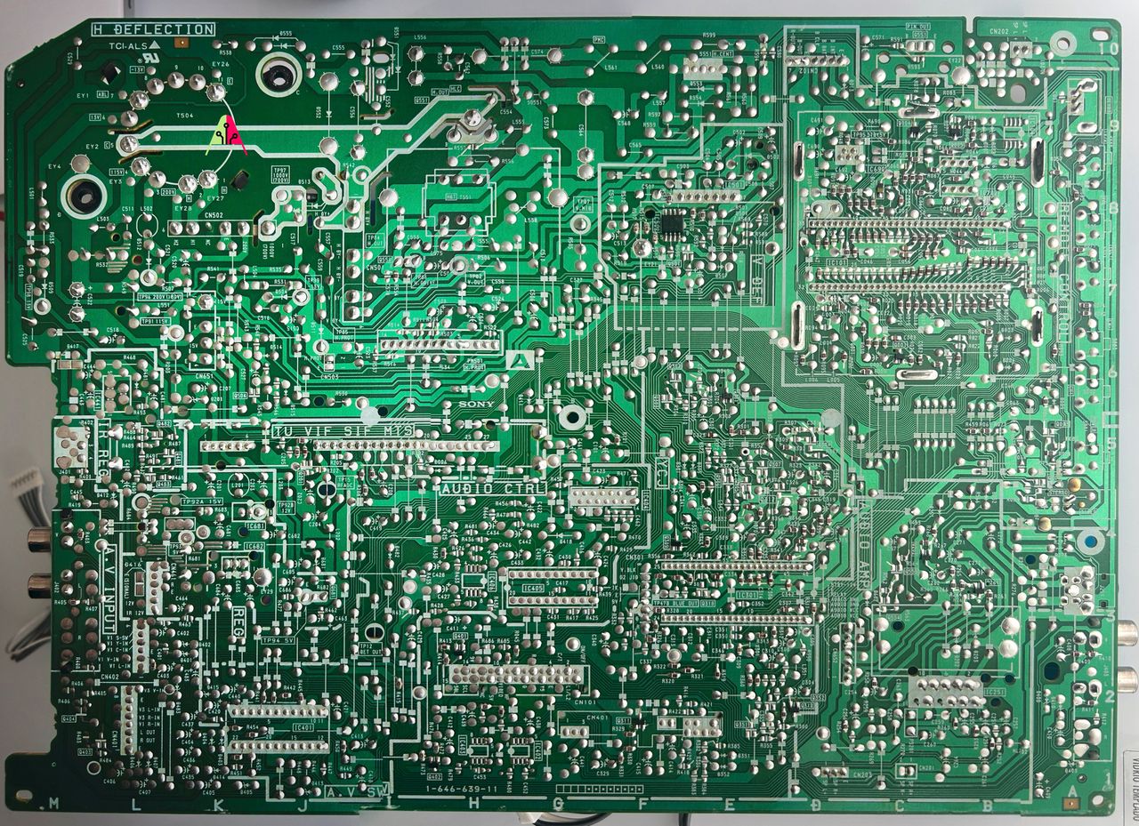
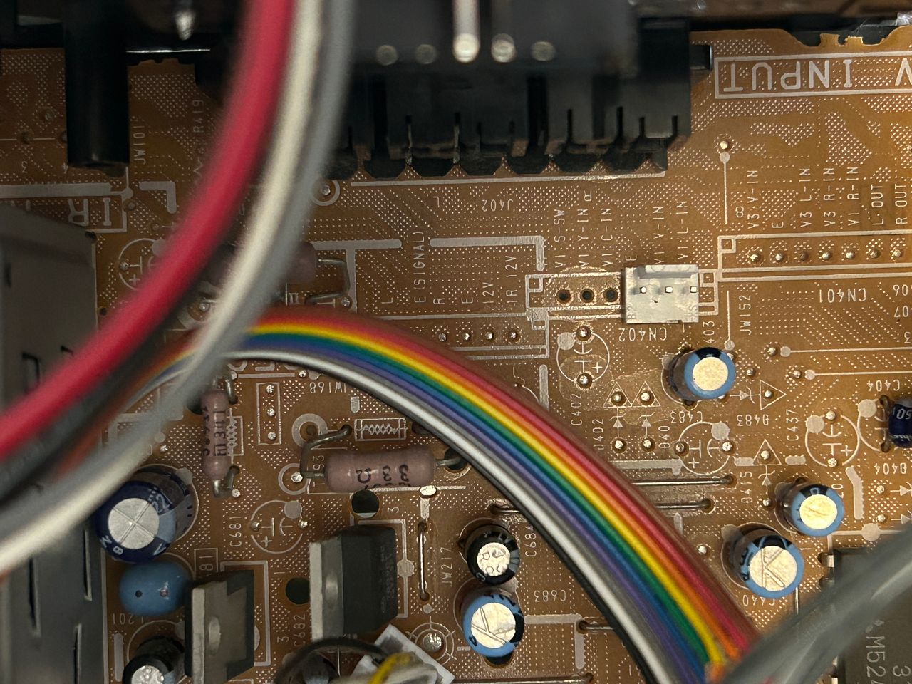
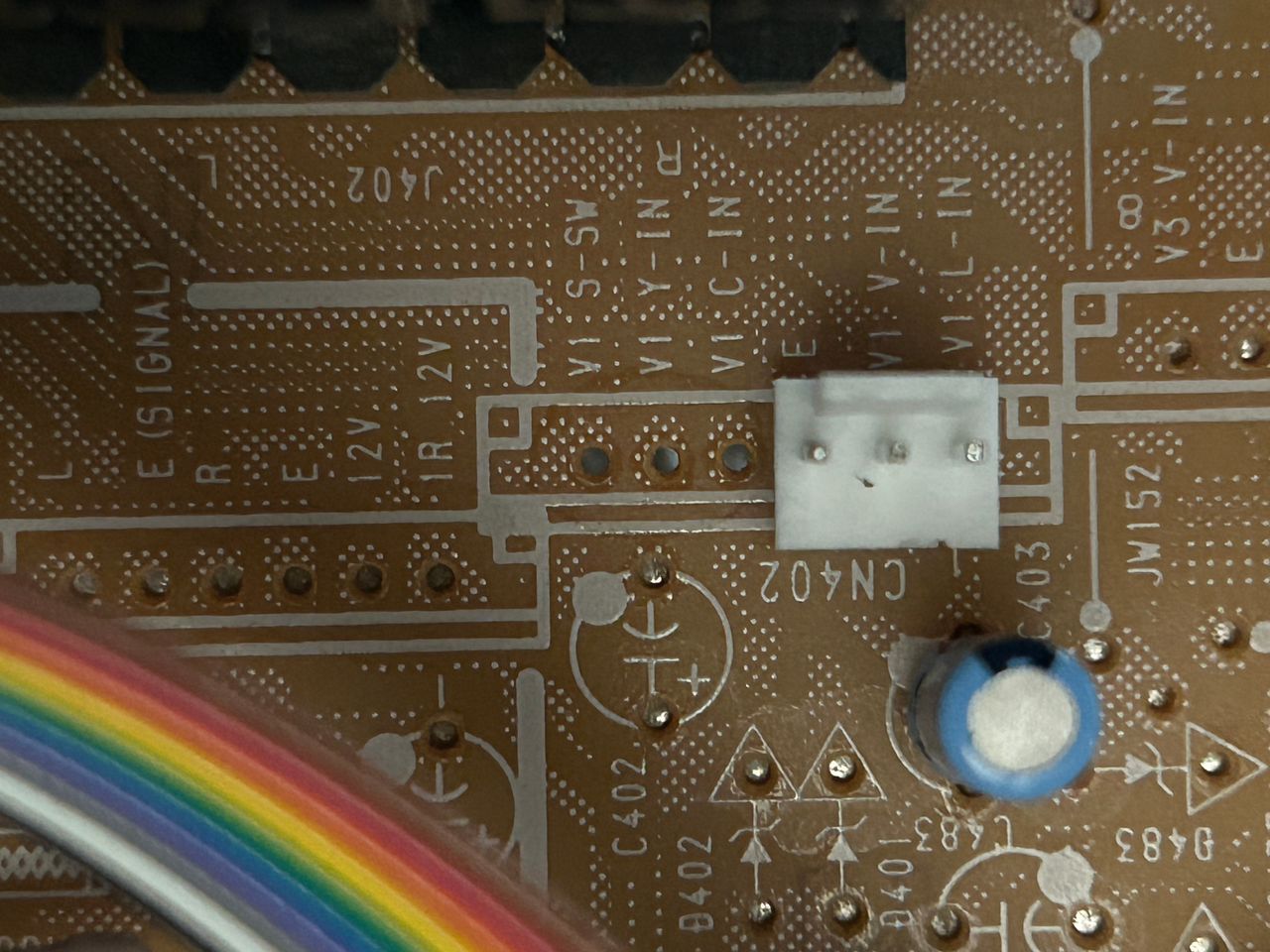
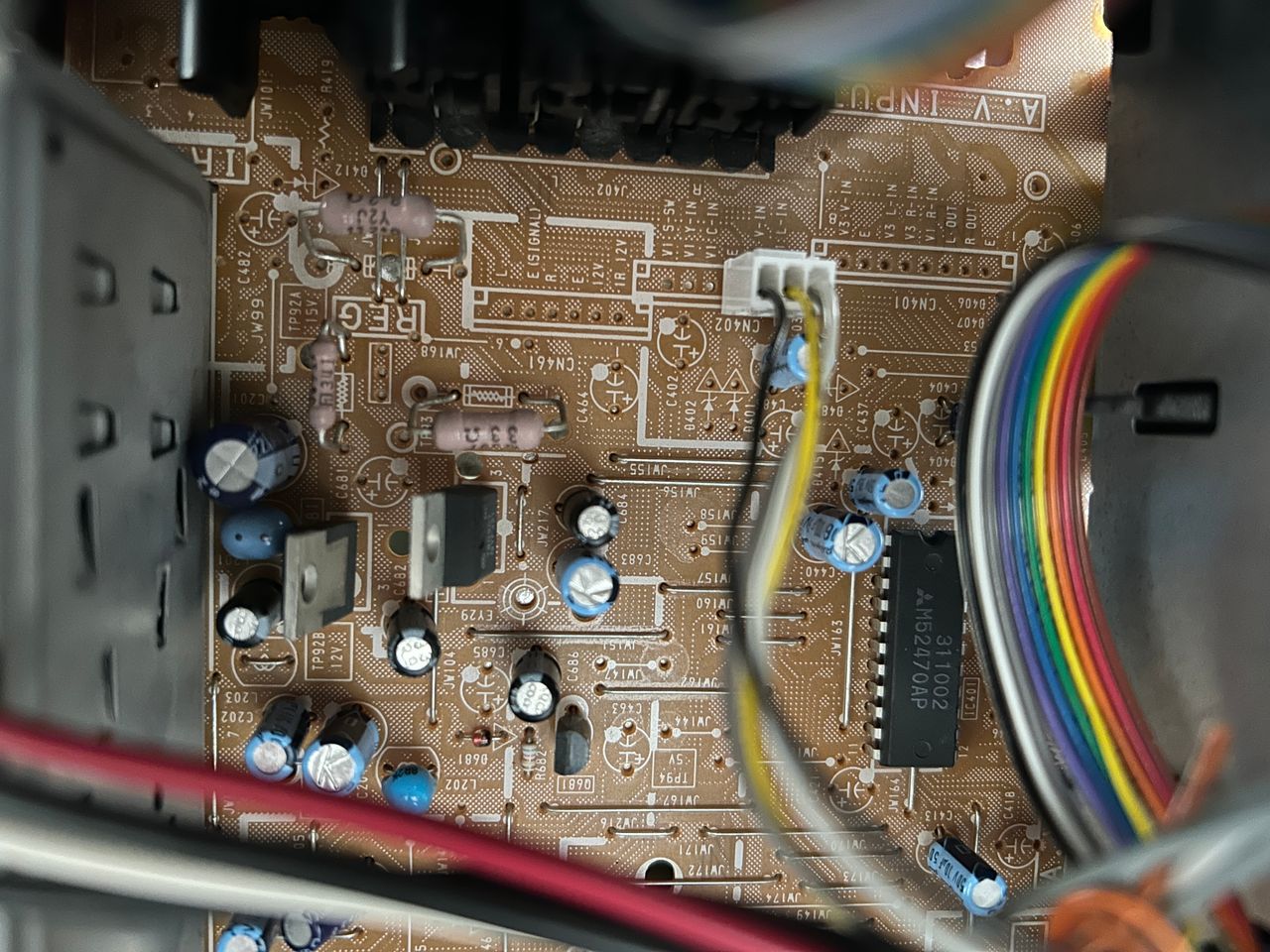
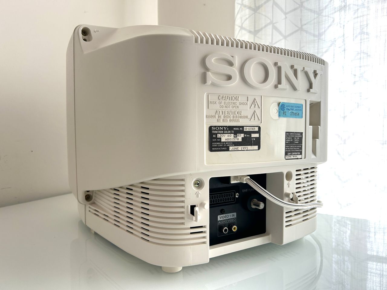
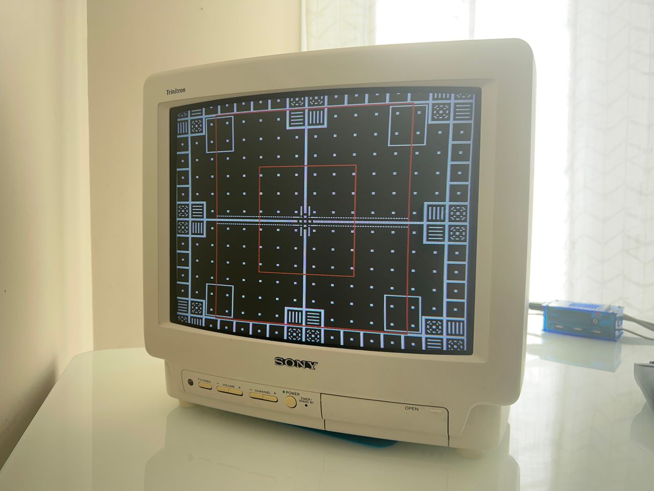
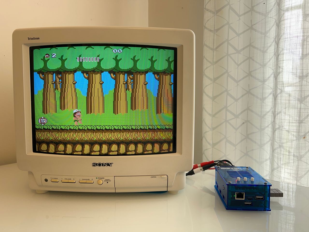
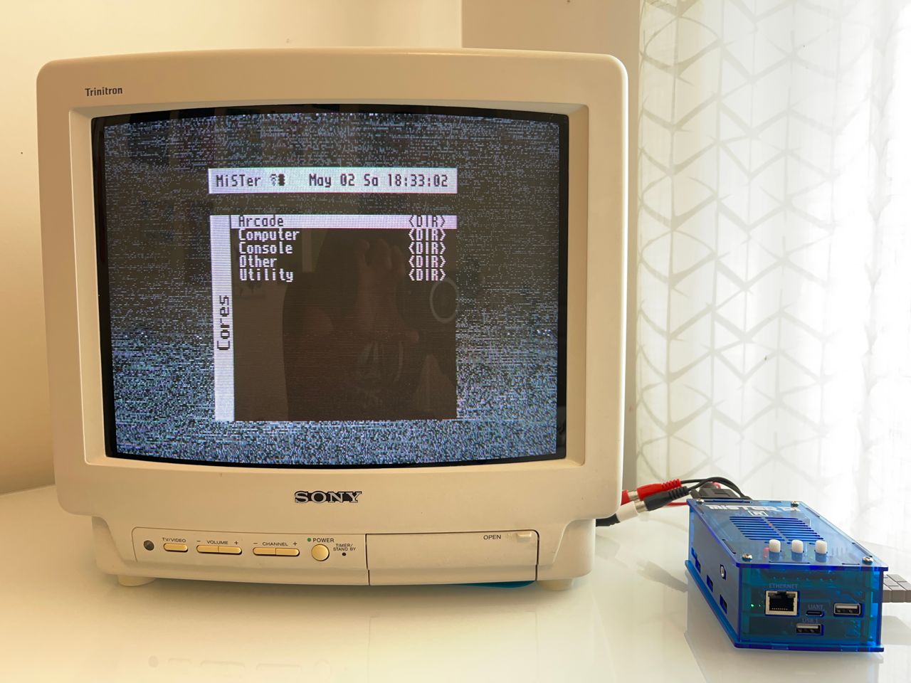
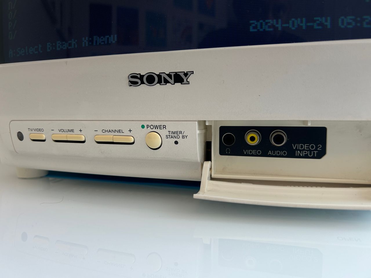
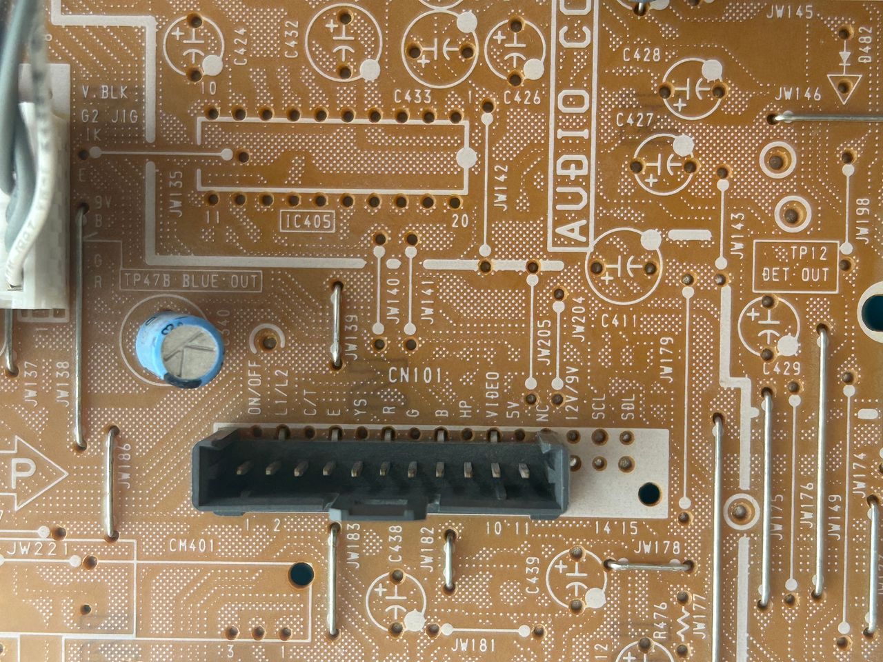
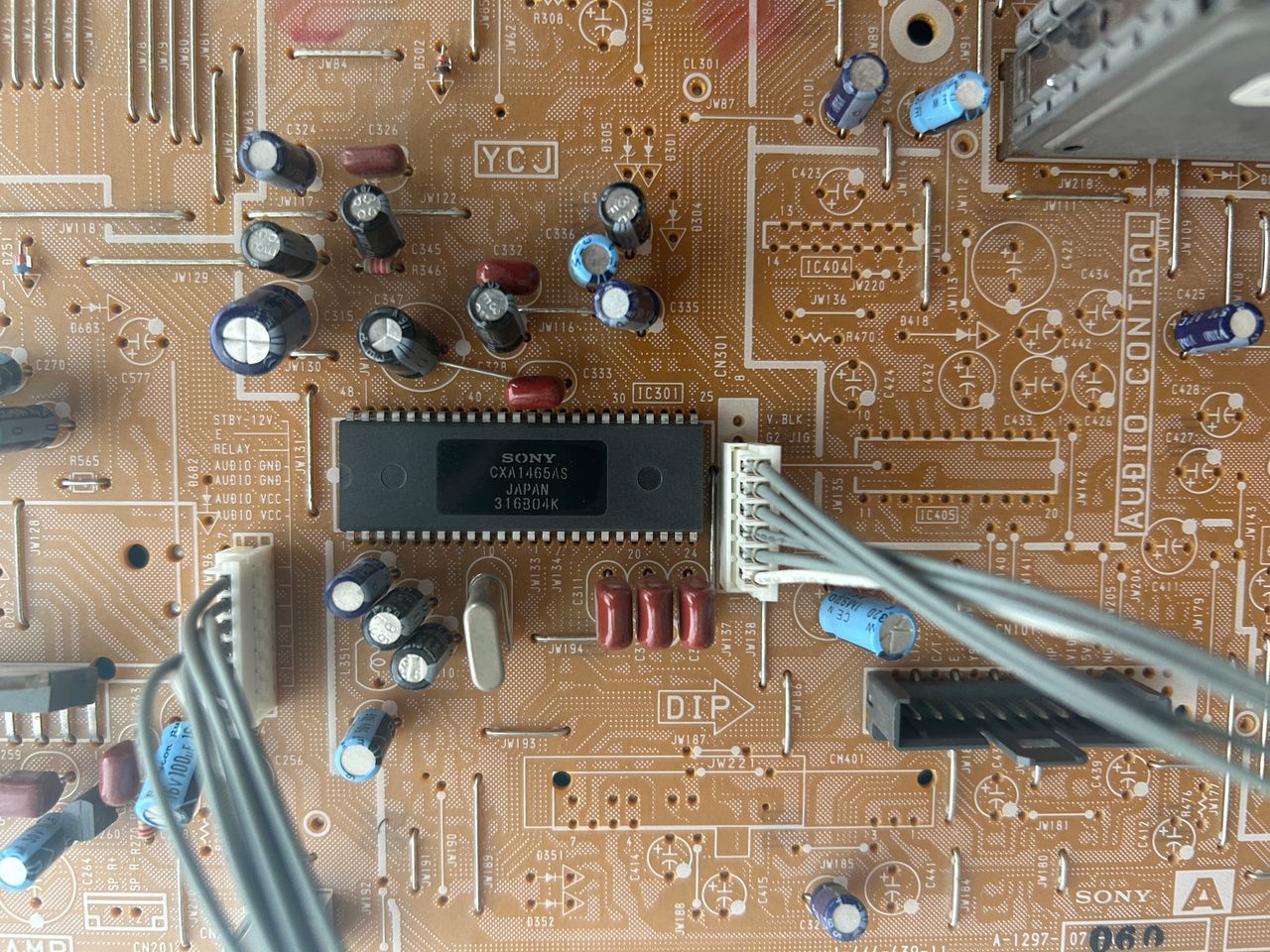
SNES in RGB mode Yoshi's Island, SNES, RGB MiSTerPi RGB Back of the TV Front inputs and buttons. I've noticed in the white version of this set, usually the buttons become yellow. Port where we can inject RGB, blanking and source 5V. Jungle IC