Sony (BN-1) KV-9PT50
Sony (BN-1) KV-9PT50 CRT RGB mod
I want to share with you a delightful 9" Sony CRT - KV-9PT50 that I've worked on. Although the CRT and tube had experienced some usage, they were reasonably average in quality. Over time, the white plastic housing had become slightly brittle due to internal heat and some parts of it had some cracks. After meticulously sealing the cracks with epoxy and super glue and implementing the RGB modification, the overall appearance significantly improved. My goal was to achieve a professional finish without any switches, massive SCART port, or multiple BNC ports. Fortunately, the XRGB specs came to the rescue, enabling me to achieve this desired outcome. Hardest part of the mod was to create the custom cable - I think I have a potential solution for this in future.
About Sony KV-9PT50
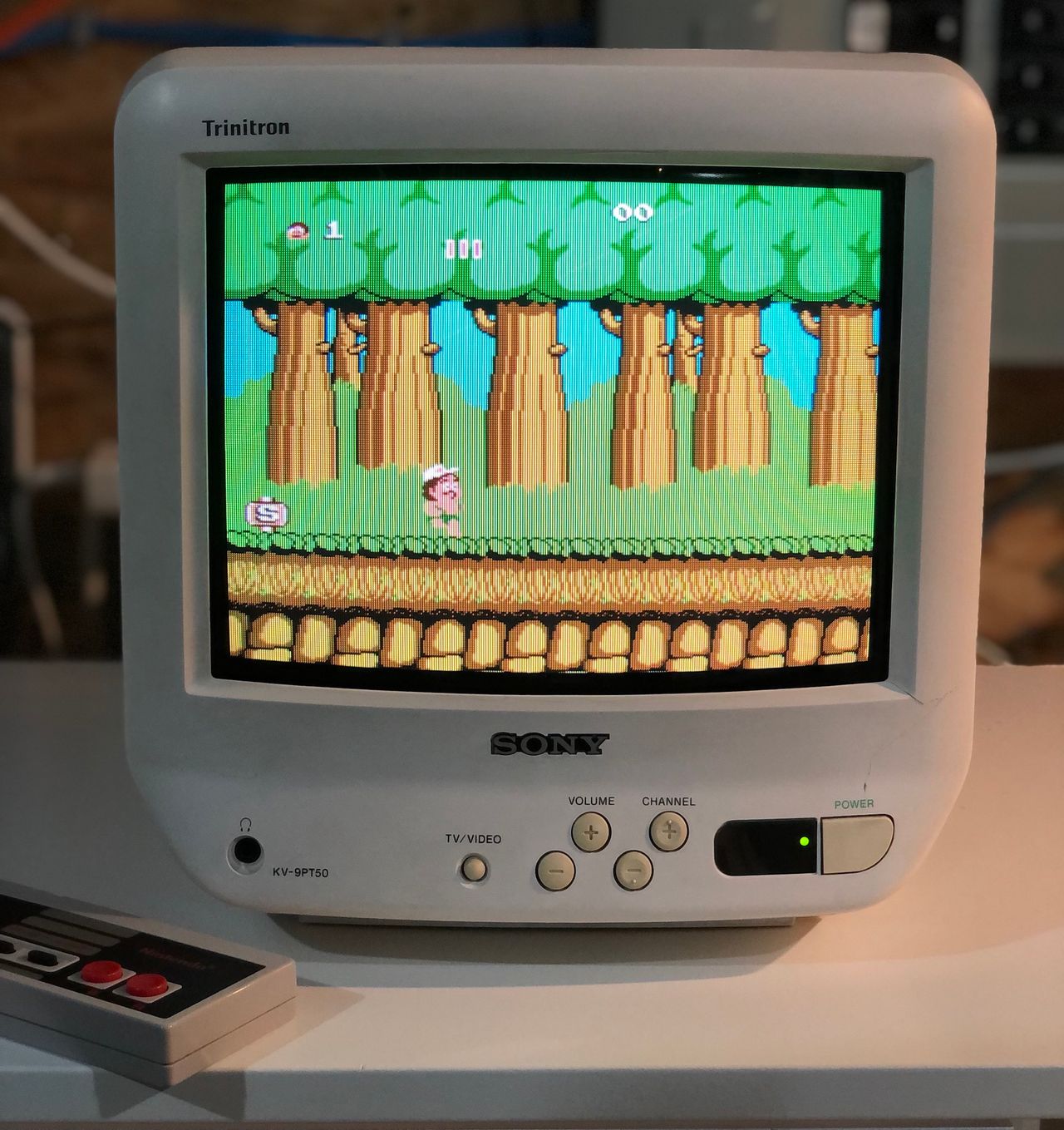
The Sony KV-9PT50 is a 9" cabinet-mount Trinitron TV designed for kitchen use. It offers excellent picture and sound quality for its size and features a unique swivelling mounting bracket that lets you view the screen from almost any angle.
There are two versions of this model: the white KV-9PT50 and the black KV-9PT60. Both sets can be RGB-modded. Once RGB-modded, these sets deliver excellent image quality and fit nicely on a desk. They’re becoming increasingly hard to find, so if you come across one, now is a great time to pick it up. Note that the white version uses more brittle plastic, which is prone to cracking.
The set includes a remote control, sleep timer, rear A/V input, headphone jack, and a coiled cord system to keep cables tidy. It measures 10×10×12 inches and weighs 12 pounds.
View full CRT details and more mod examples →
This tutorial should also cover the RGB mod for the below models with the BN-1 chassis. However, there might be differences in chassis, internals etc. KV-9PT60 has a different chassis.
9" models
- KV-9PT50 (white)
- KV-9PT60 (black)
Contributors
Thank you to everyone who contributed to this guide:
CRT safety
Caution
You can die doing this! So read carefully! CRT TV is not a toy. Do not open a CRT TV. If you don't have any prior knowledge about handling high voltage devices, this guide is not for you. CRT TV contains high enough voltage (20,000+ V) and current to be deadly, even when it is turned off.
Plan of attack
Manuals and Datasheets
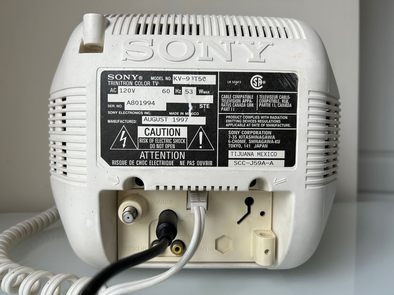
Specs
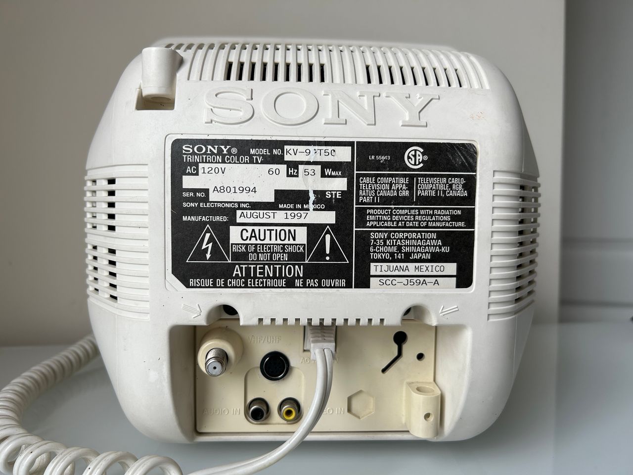
- Manufactured: Mexico (1996, 1997)
- Format: NTSC
- Chassis: BN-1, SCC-J59A-A
- Tube: Sony Trinitron A23LDU10X
- Jungle Chip: Sony CXA1464AS
- Screen Size: 9"
- Power: 53 W
- Weight: 12 lbs
- Inputs: Composite, RF
Schematics
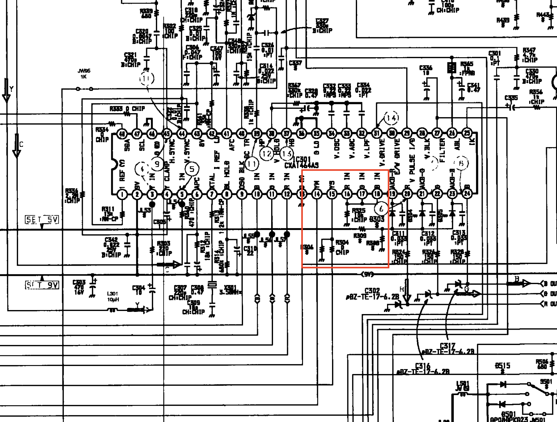
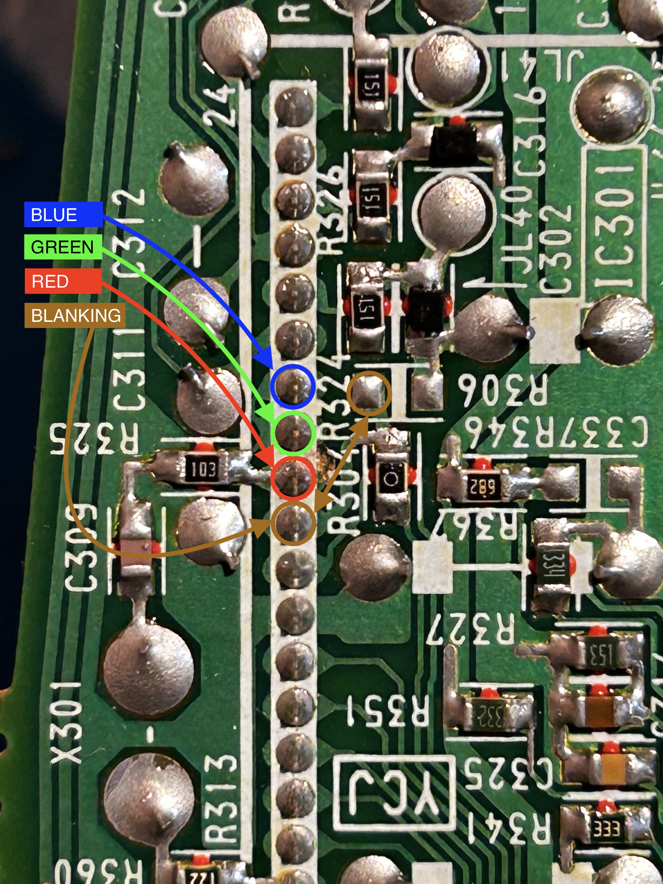
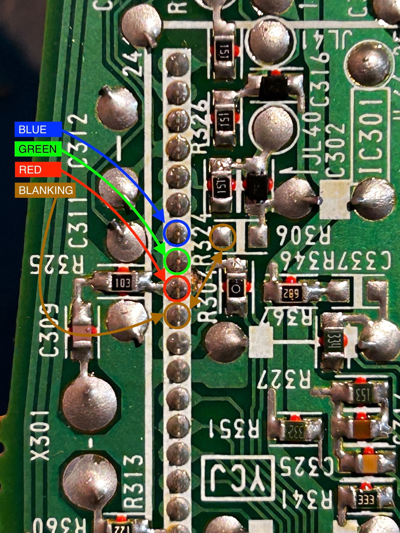
Blanking (Ys), Red, Green, Blue lines are exposed on pin 15, 16, 17, 18 of the CXA1464A9 chroma IC.
RGB mux diagram
Prepare the mux diagram. If you are building your own circuit, this diagram should help.
Performing the mod
You can't ask for a more straightforward RGB mod.
Fortunately this chassis doesn't require any muxing. You can pass R, G, B through a 0.1uF, 75ohm terminated wire directly to the chroma IC301. Blanking (Ys) can be fed through a 1kΩ + 0.7V didoe to pin 15 of the chroma.
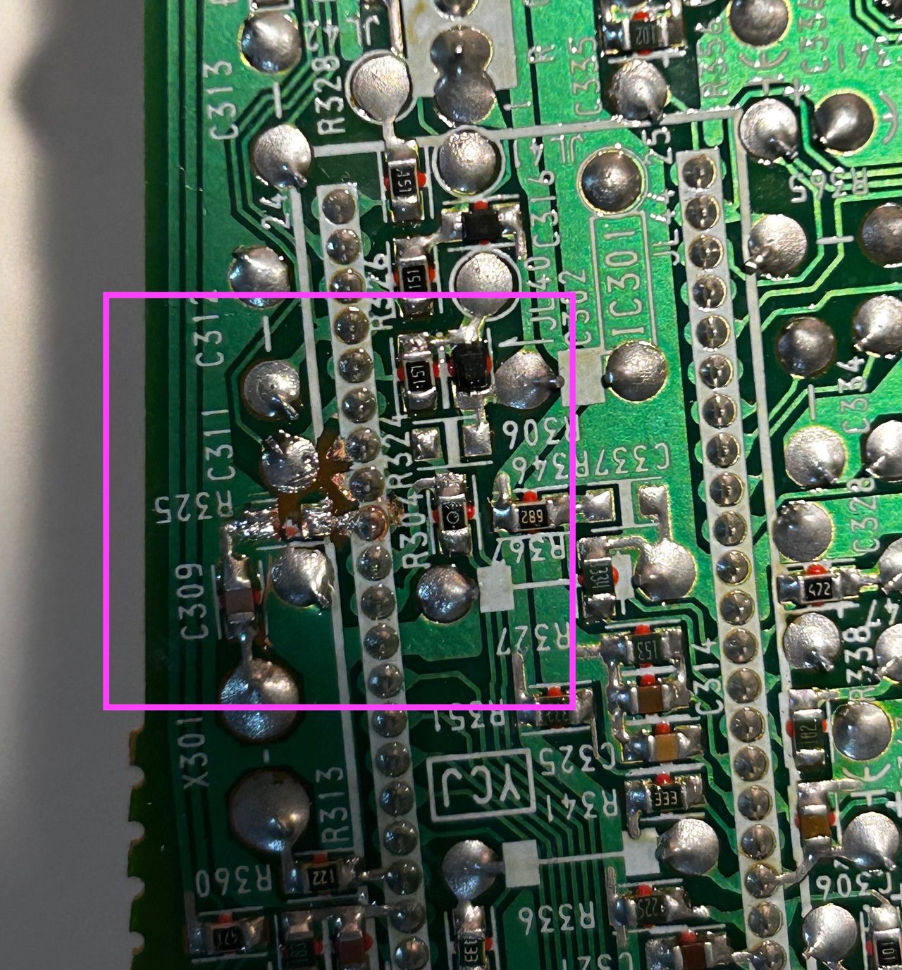
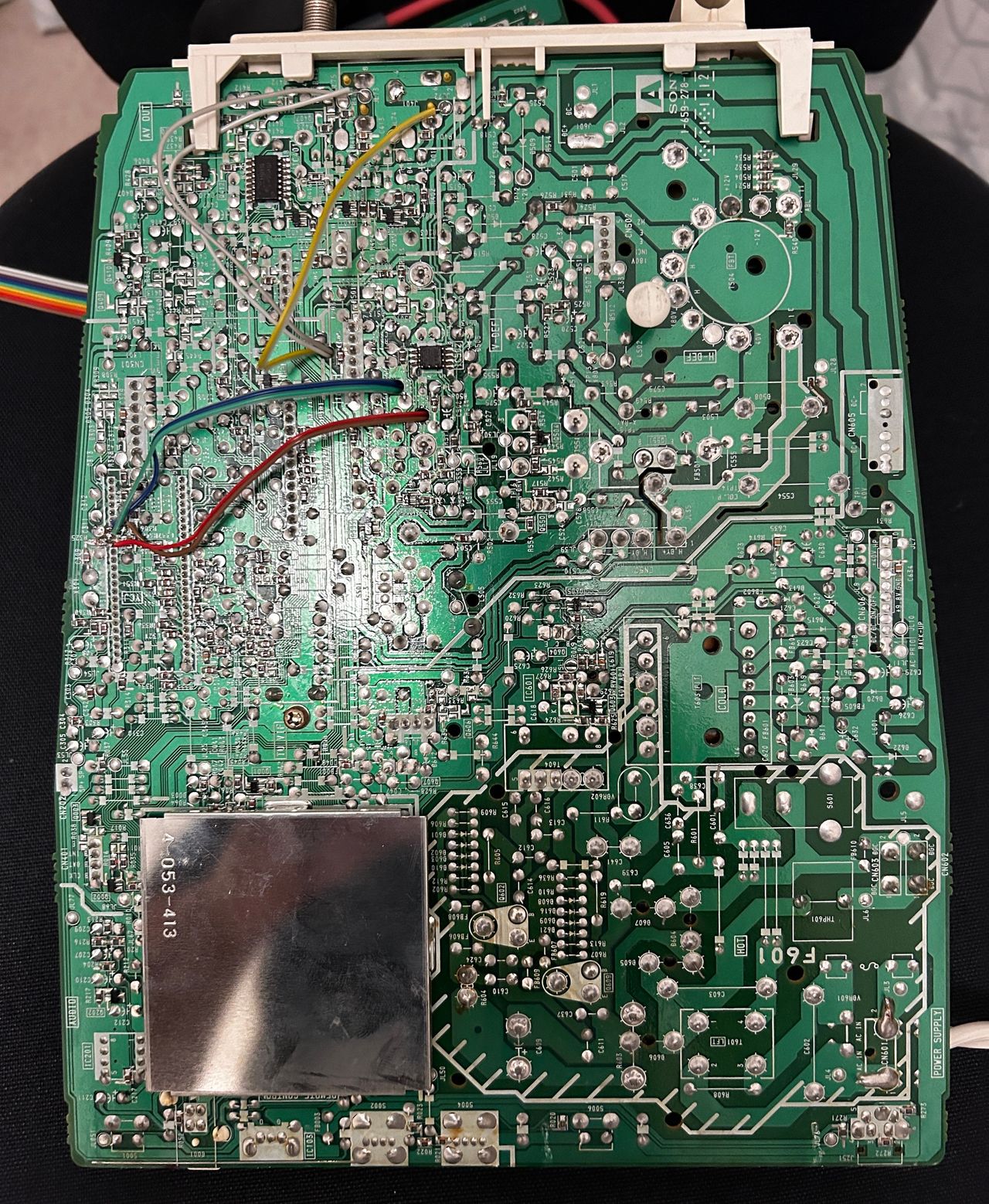
STEP 1: Free the RGB inputs
- Remove the R325 ground resistor (10kΩ) from the board.
- Carefully cut the traces on the board to ensure that the R, G, and B traces are no longer connected or shorted together.
This method provides the best approach that can be easily reversed back. It is important to avoid cutting the pins on the chroma IC as you can easily damage those pins. Replacement chroma IC can be difficult to find, so it's strongly advised against cutting the pins.
On the other hand, cutting the traces is a relatively straightforward process. To do so, you can use a small sharp hobby knife or a screwdriver to carefully scratch away the traces.

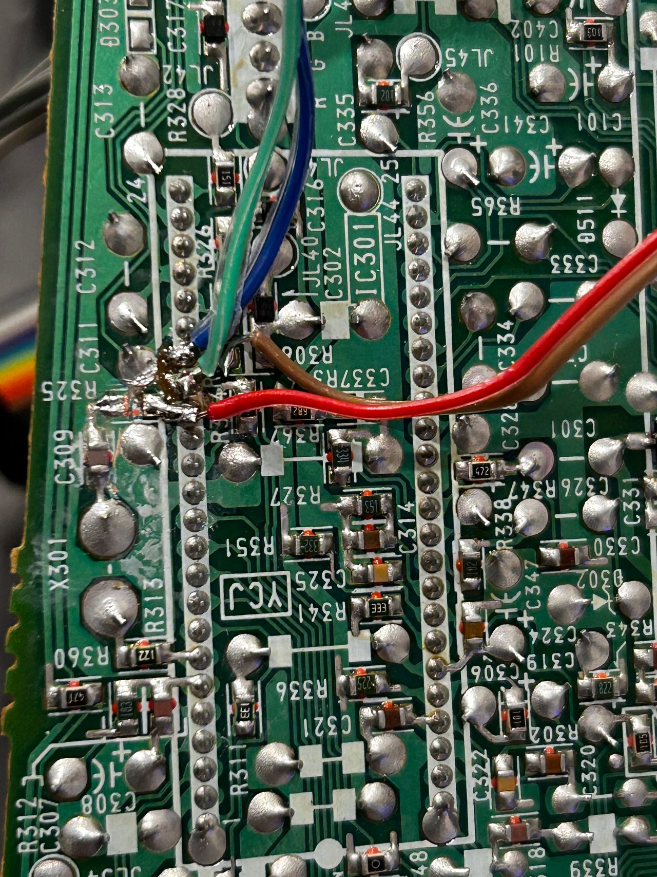
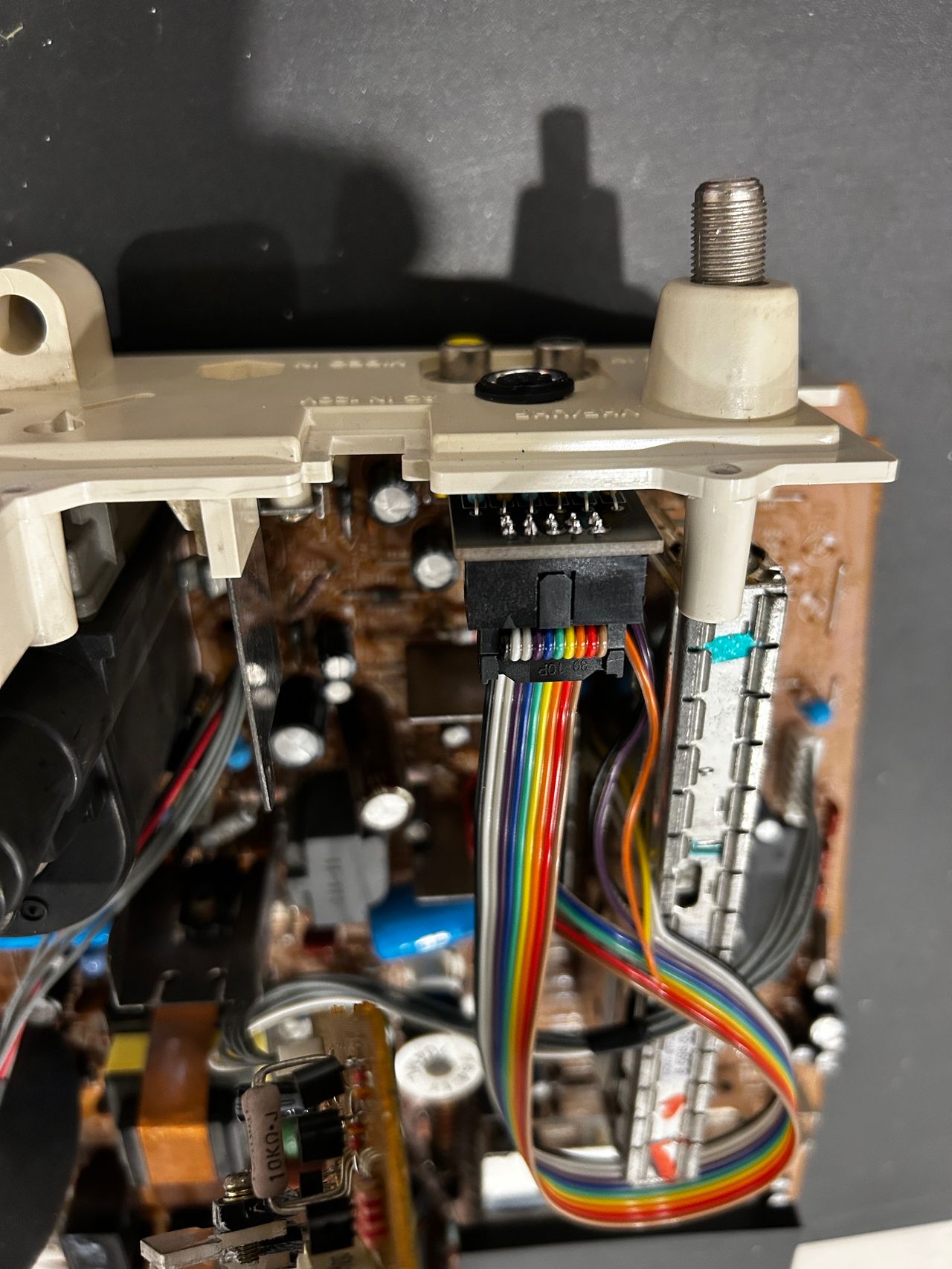
STEP 2: Connect RGB and Blanking
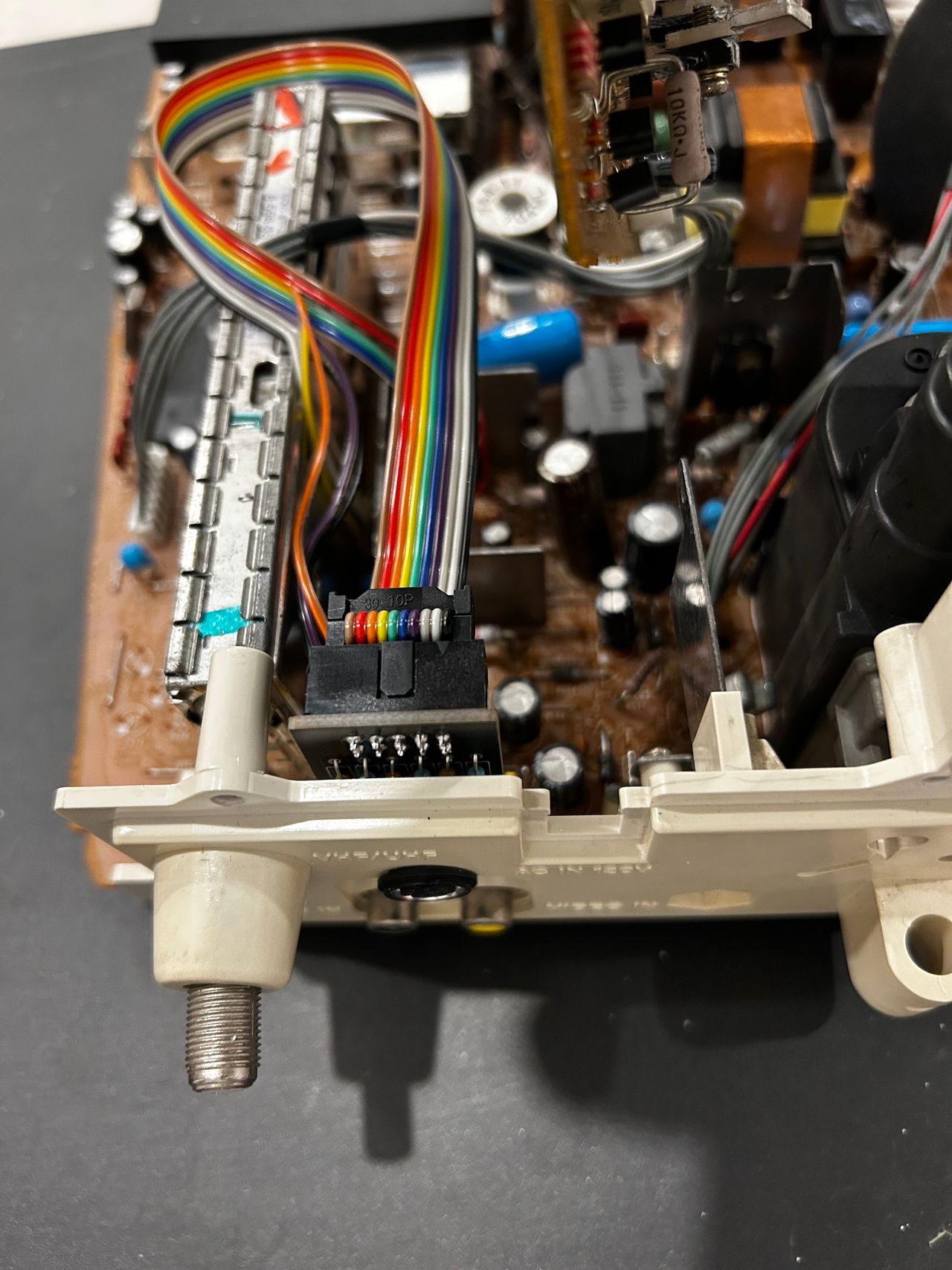
You don't need a long ribbon cable for this mod. Shorter the cable the better as it reduces interferece.
See picture below to see where R, G, B and blanking wires should be connected. Blanking (Ys), Red, Green, Blue lines are exposed on chroma pin 15, 16, 17, 18 respectively.
![]()
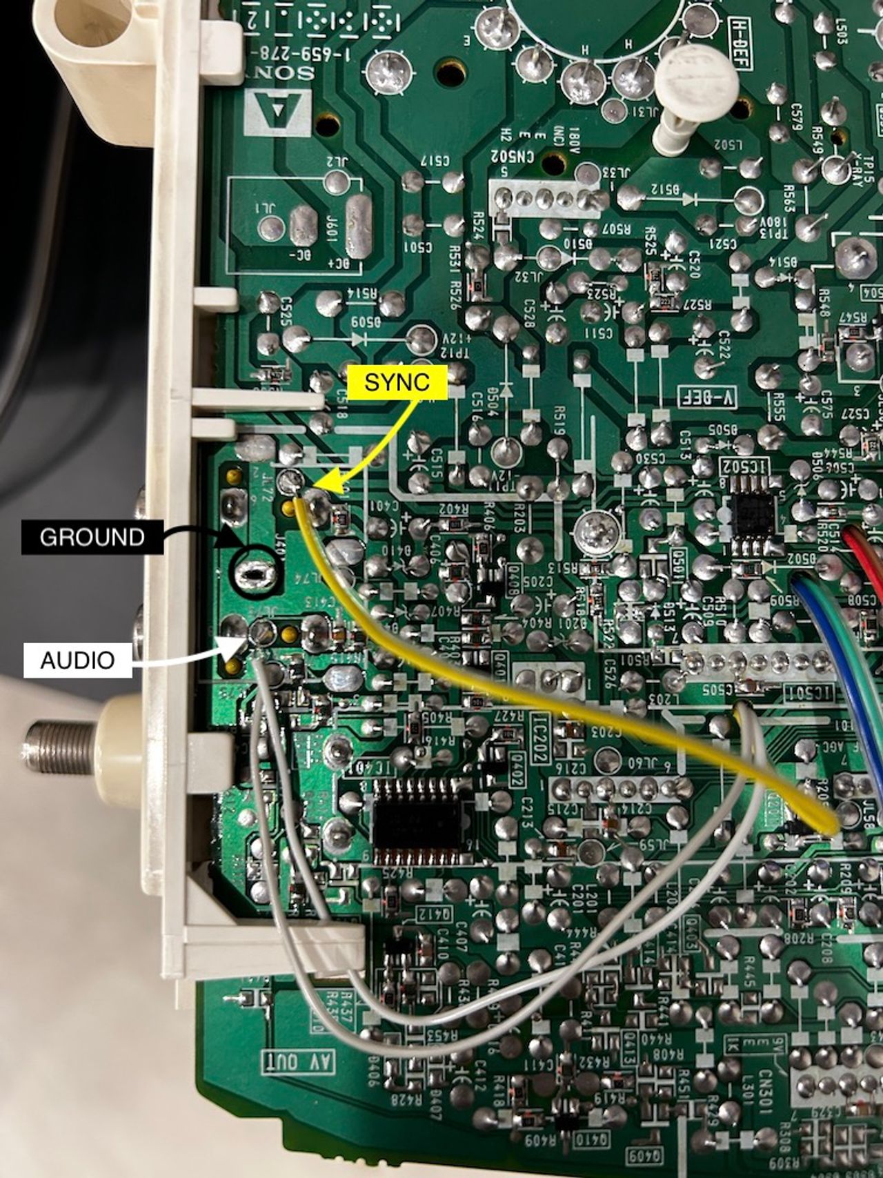
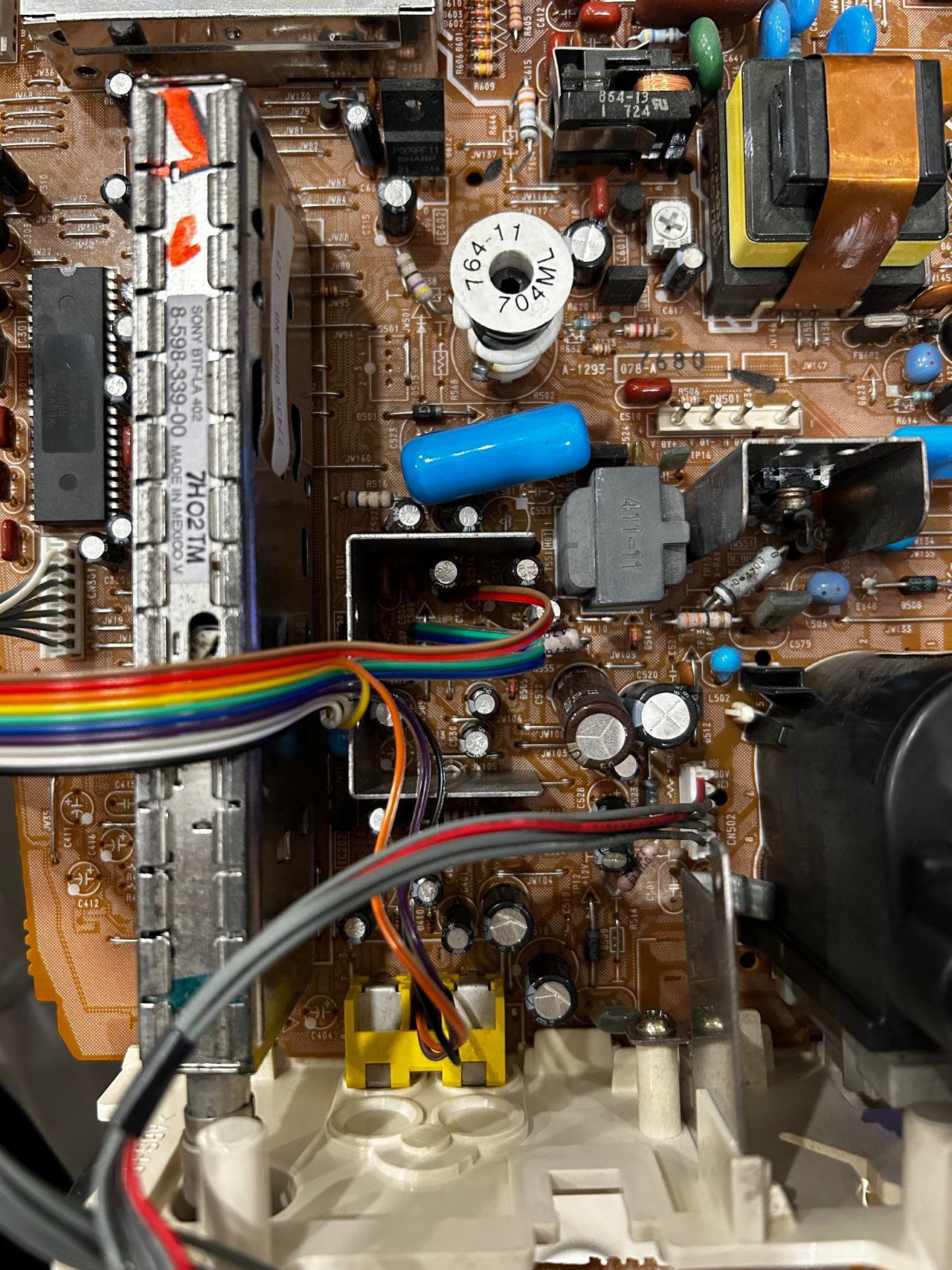
STEP 3: Connect Sync and Audio
The KV-9PT model exclusively supports mono audio. In this configuration, we will connect both the left audio (grey) and right audio (white) wires together, and directly connect them to the mono audio input. To ensure proper current and voltage delivery to the mono input, two 1kΩ resistors on the mux board will be utilized. The accompanying pictures below illustrate the wiring setup for visual reference.
The good news is that there are already ideal soldering points available for connecting these wires.
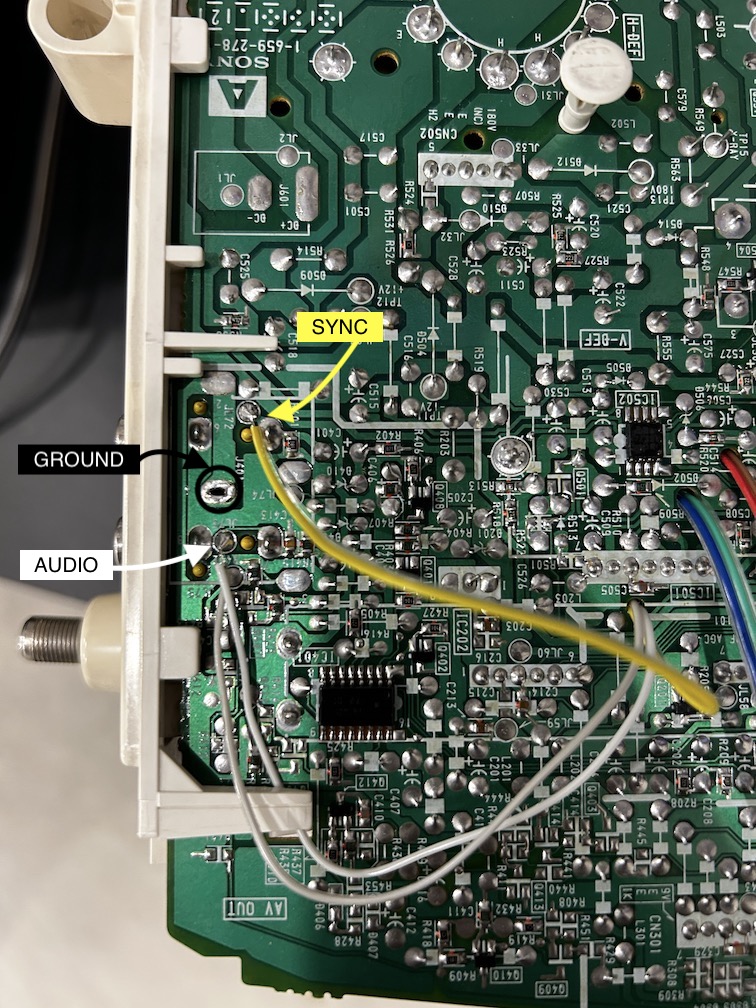
Sync wire (yellow) will be connected directly to the composite input.
To establish a common ground connection, we will connect and solder all the ground wires (black, orange, and purple) together. This consolidated ground connection will be securely soldered to one of the ground vias located near the composite input.
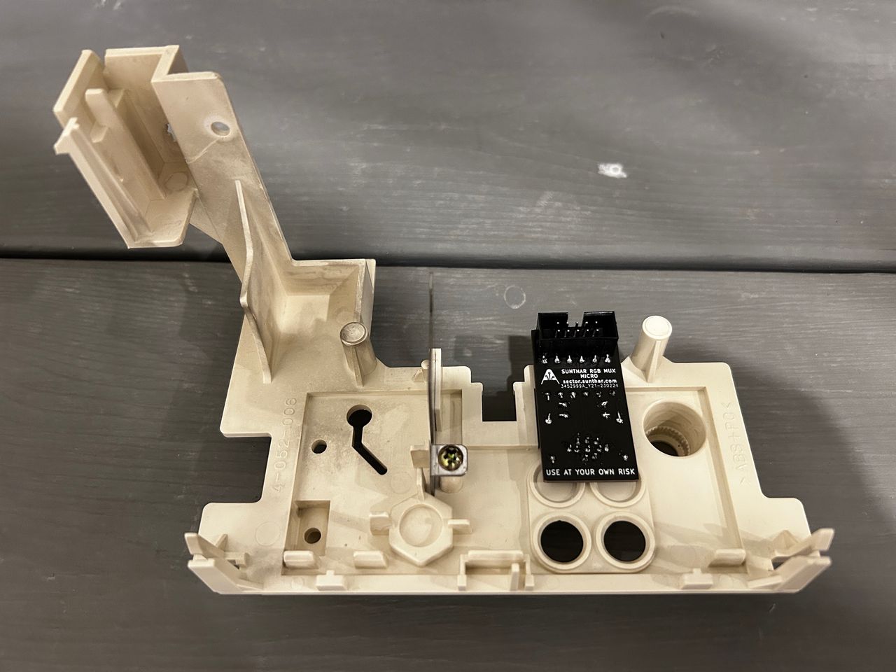
STEP 4: Build your mux board (using the micro RGB board)
This mod uses the RGB mux board. This is optional, but will make your mod easier and stable. You can also create the circuit presented in the schematics above without the board. Please also checkout the mux calculator to play with your own values.
| On Sony CRT Chassis | KV-9PT50 |
|---|---|
| 0.1μF caps replaced | No |
| Add diodes on chassis RGB lines? | No |
| Add blanking diode on chassis | No |
| RGB mux board | KV-9PT50 |
|---|---|
| Mux board RGB termination (R1, R2, R3) | 75Ω |
| Mux board RGB input capacitors (R4, R5, R6) | 0.1μF |
| Mux board Audio LR (R7, R8) | 1kΩ |
| Mux board blanking diode (R9) | 1N4148 |
| Mux board blanking ground resistor (R10) | open |
| Mux board blanking resistor (R11) | 1kΩ |
Compatible mux boards:
Caps were used on the mux board instead of RGB inline resistors.
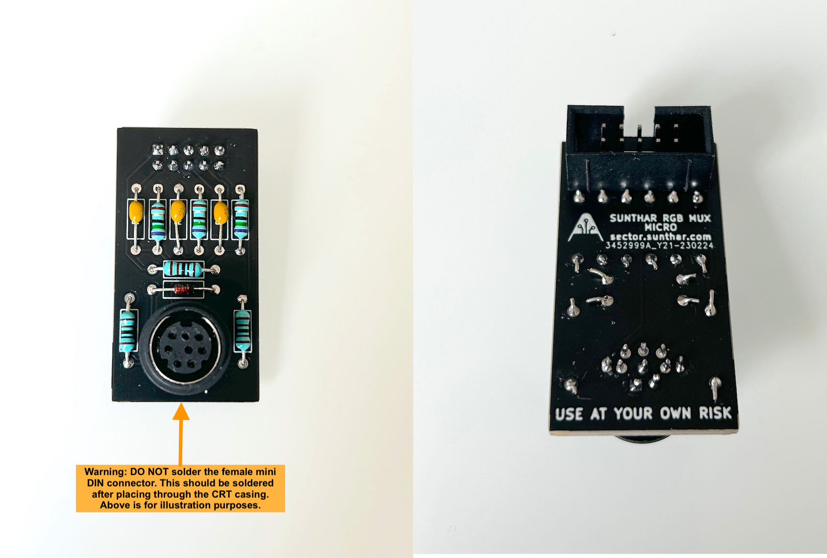
Warning
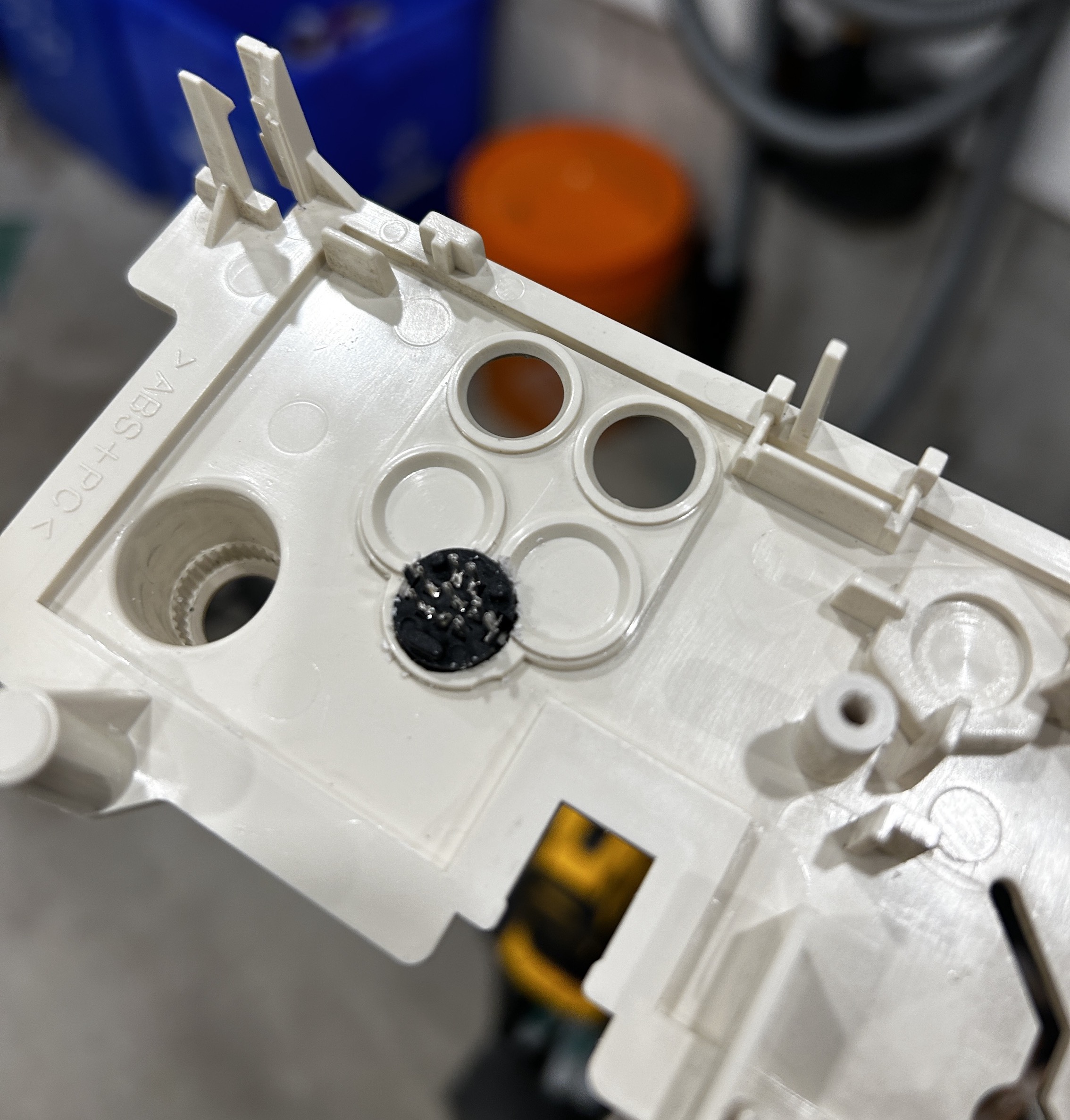
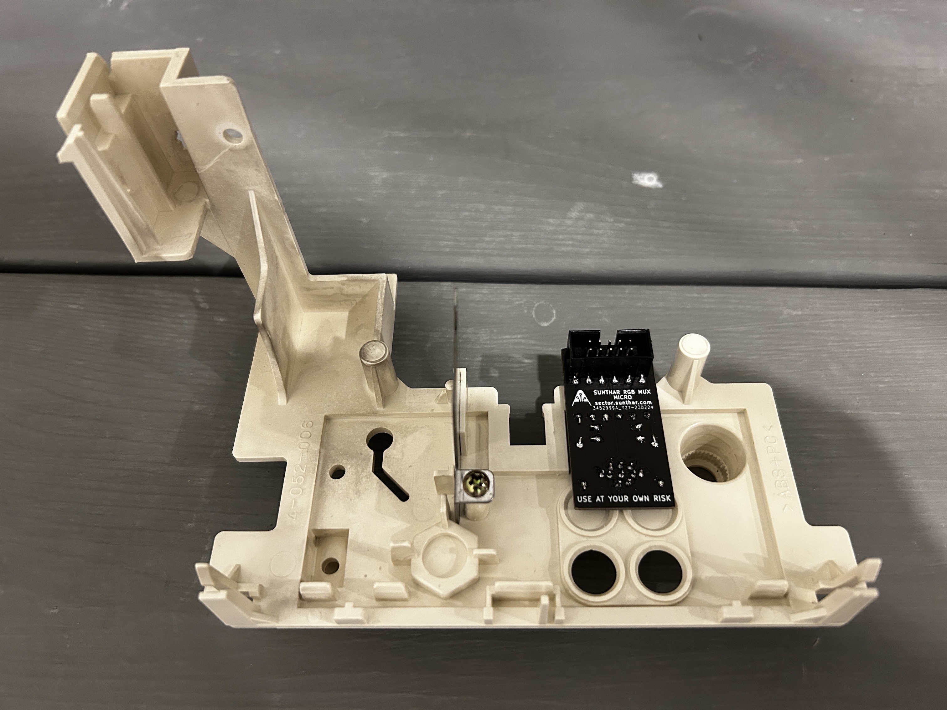
In the picture above, I'm showing the MD8 connector placed in the PCB for illustration purposes. Yet, for the practical modification, you will initially need to insert the MD8 female connector through a hole that is precisely sized to allow the body to fit through. Following this, you can solder the PCB by aligning the pins accordingly. It may be necessary to use adhesive like super glue to secure the MD8 connector in position, preventing any rotational movement. See pictures below.
Buy your RGB mux board with the necessary parts to complete this mod
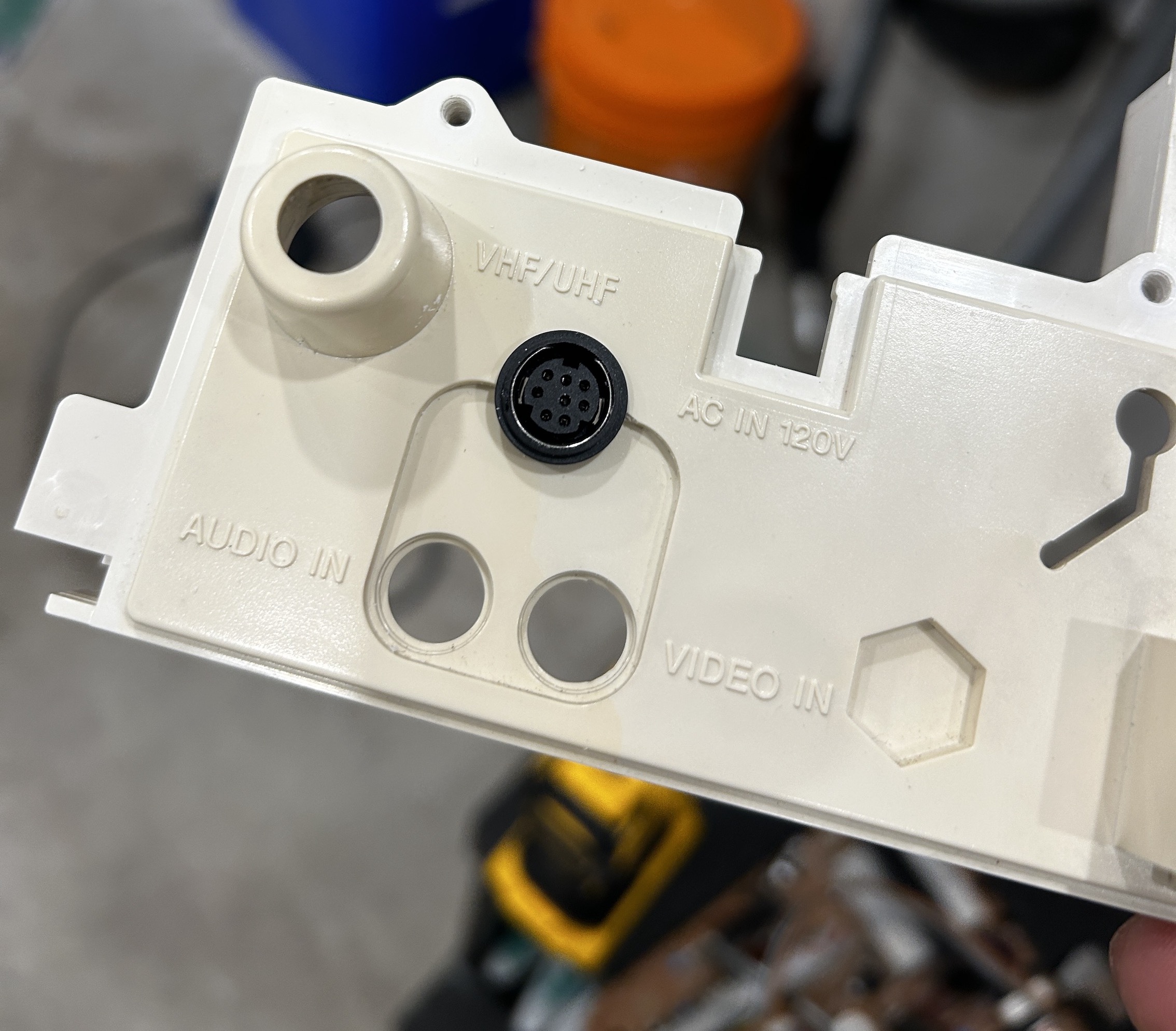
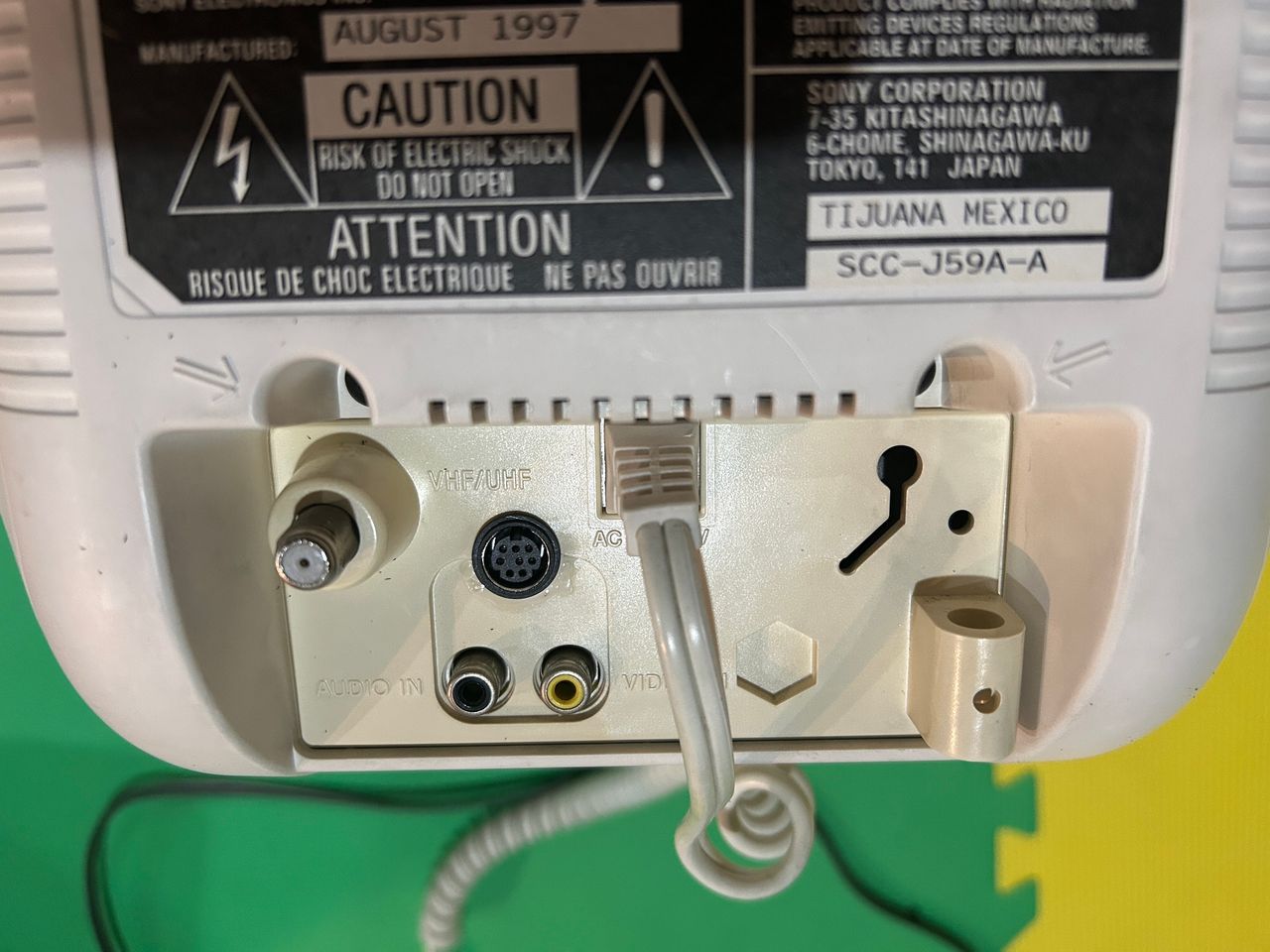
STEP 5: Attach the female SCART connector to TV
I chose the XRGB-mini port for the RGB mod here. This CRT had limited space and an RGB port needed to be carefully planned.
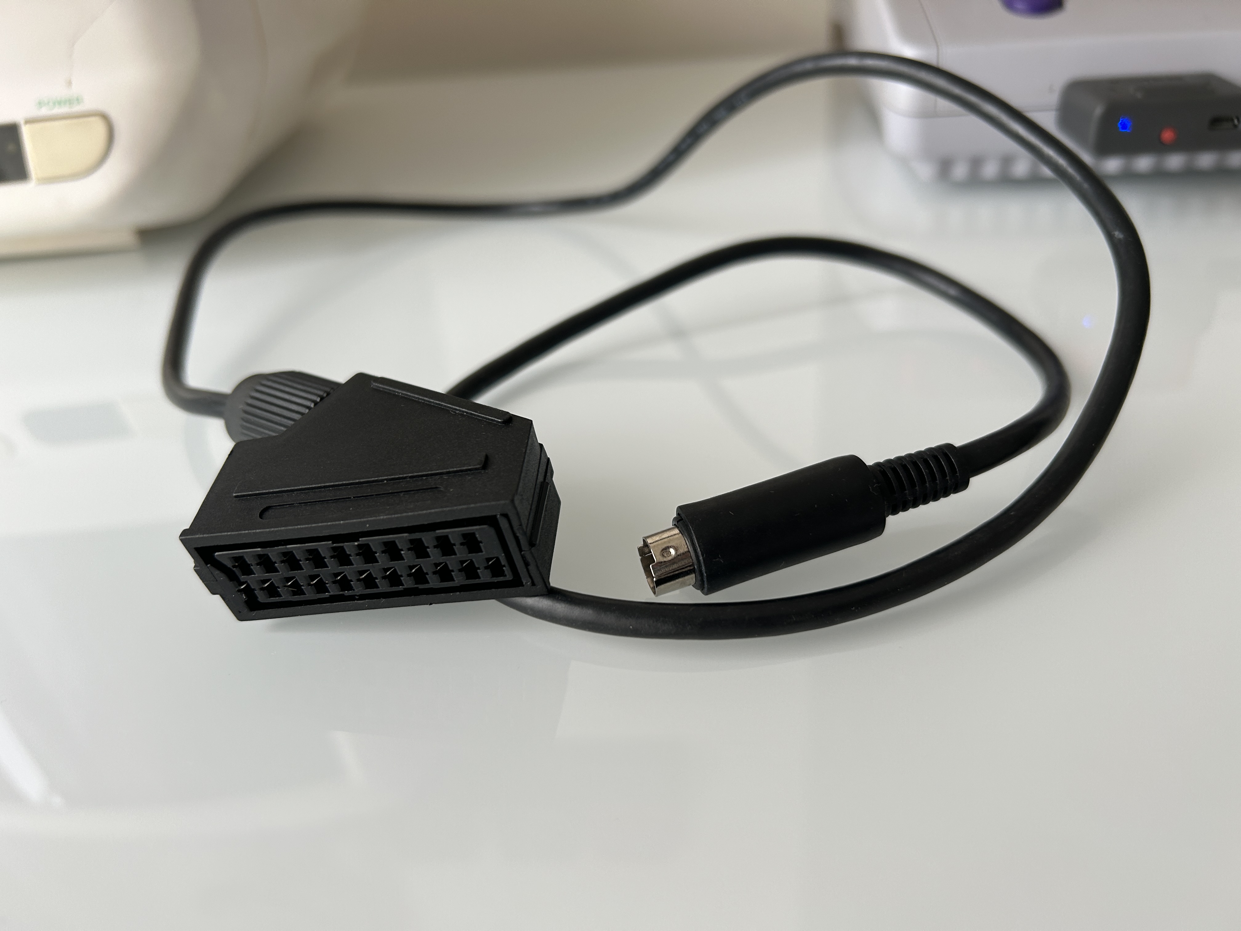
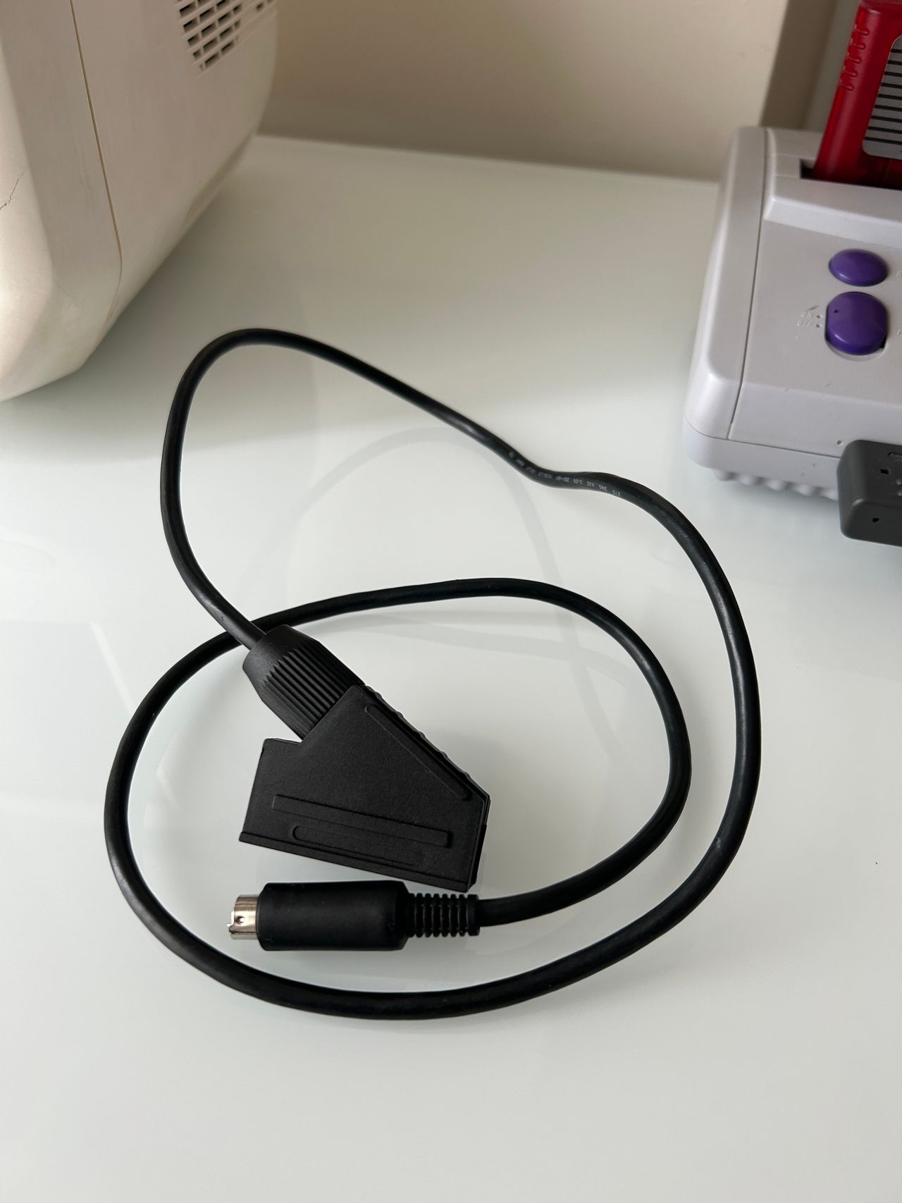
STEP 6: Make the SCART breakout cable
I'm using the XRGB-mini to SCART here. You can also use MD to SCART cable as well (which might be more readily available).

Pictures of the mod
OSD
Menu on top of the Contra III game 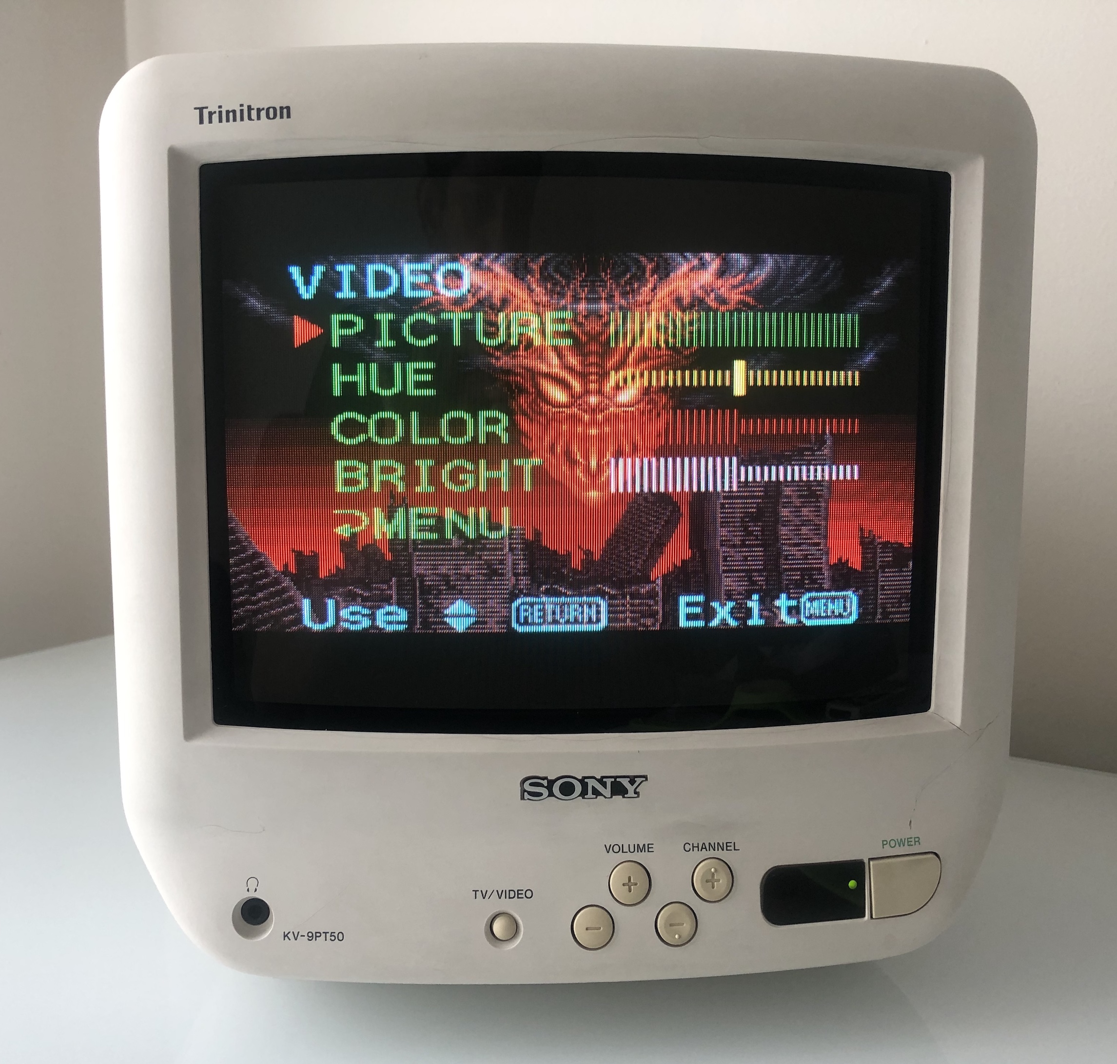
Games
NES - Everdrvive Menu 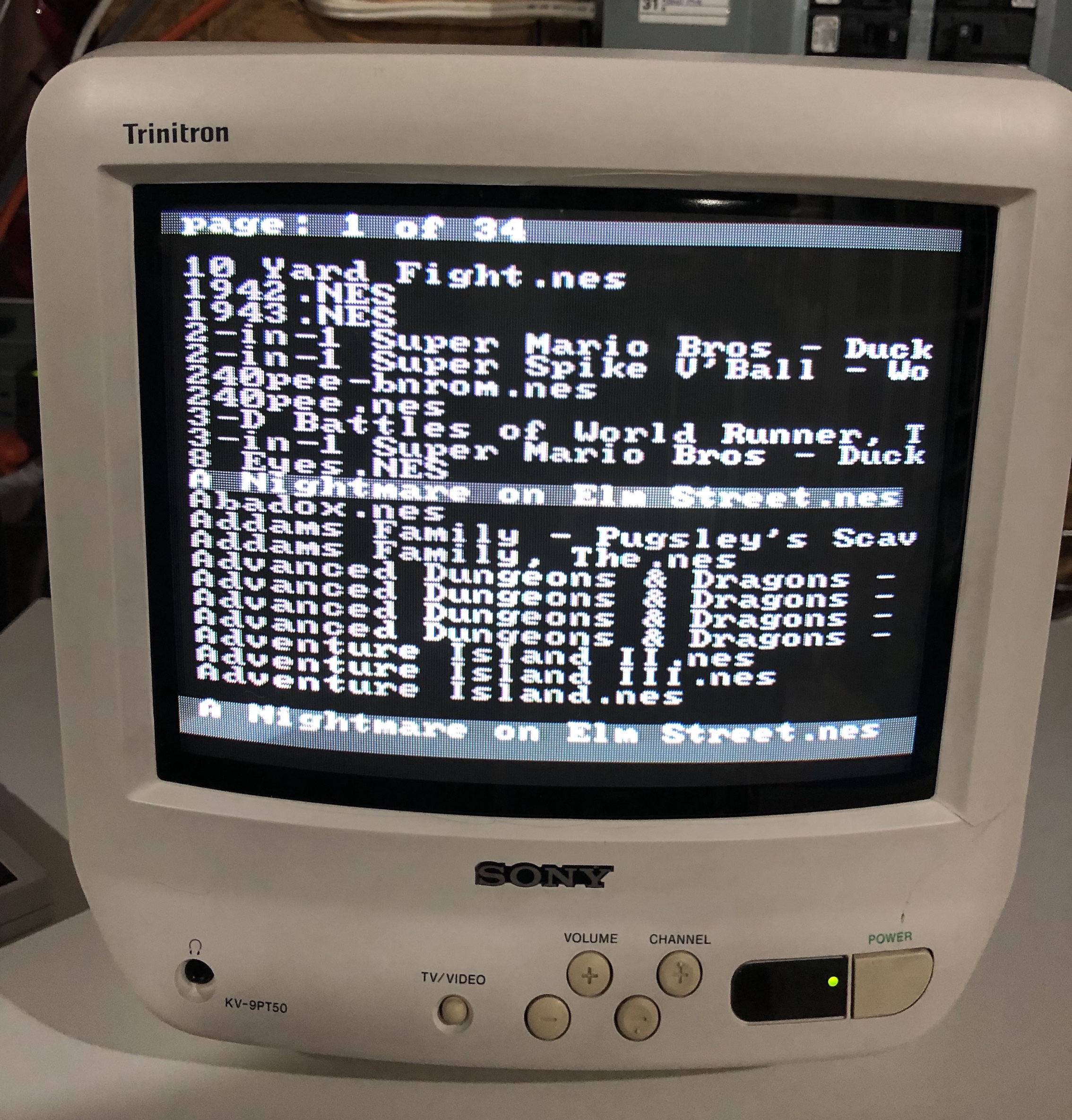
SEGA Genesis - Sonic 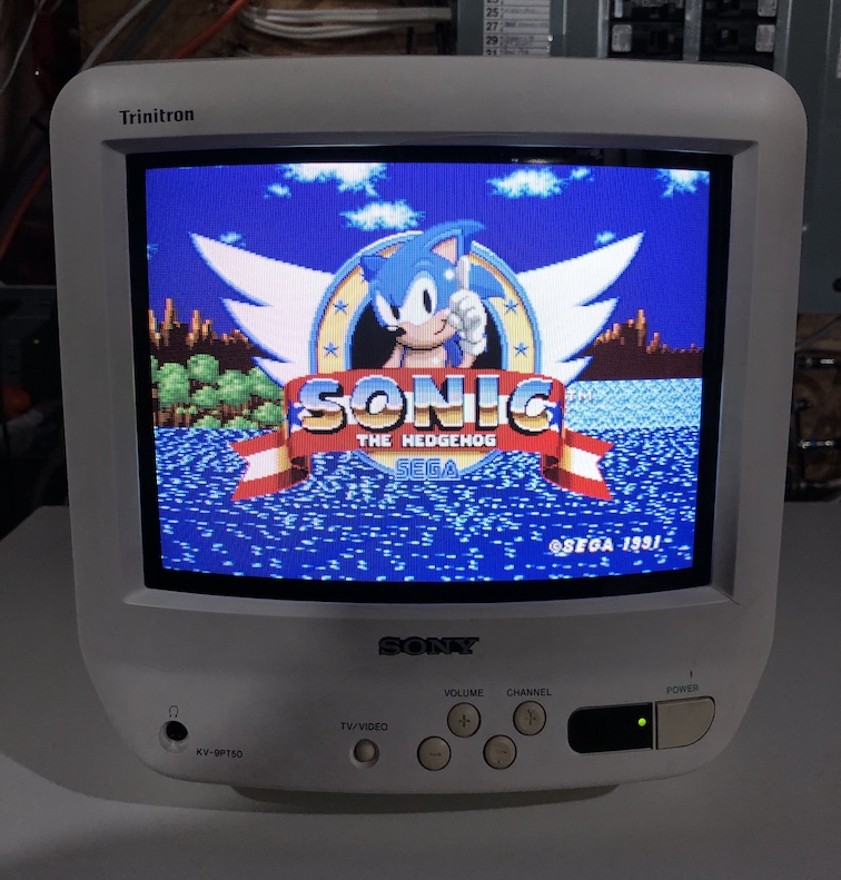
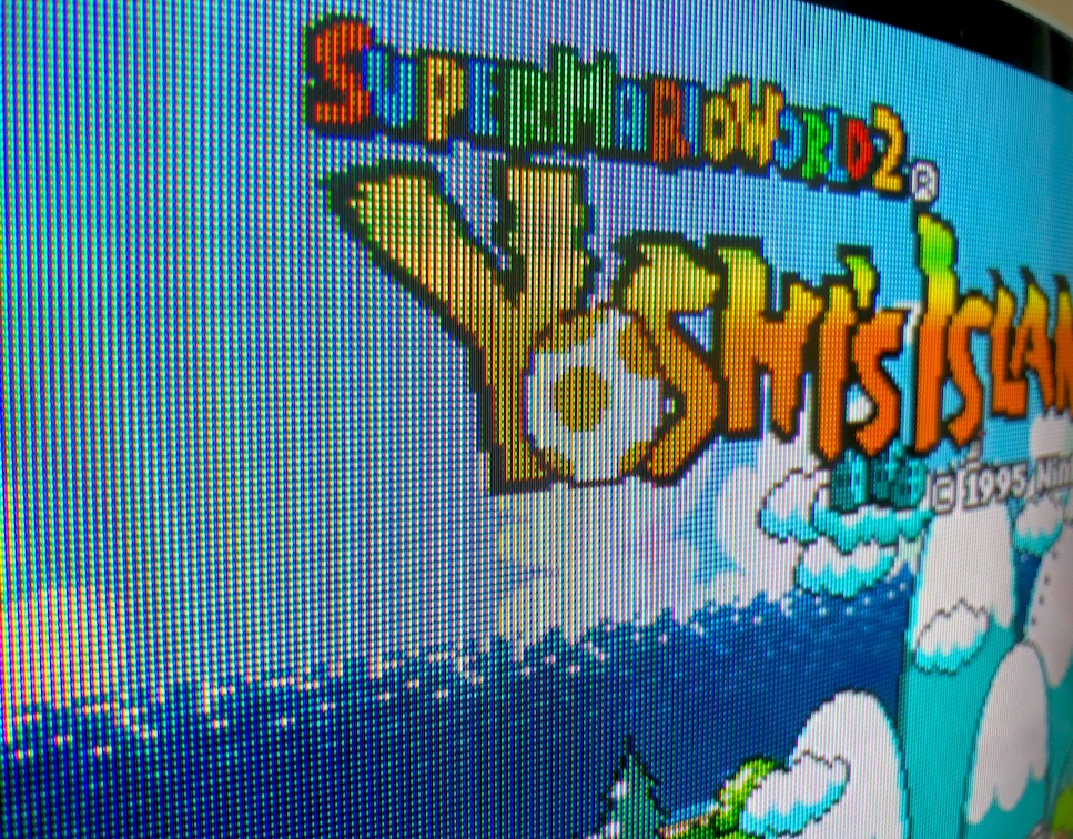
SNES - Yoshi's Island 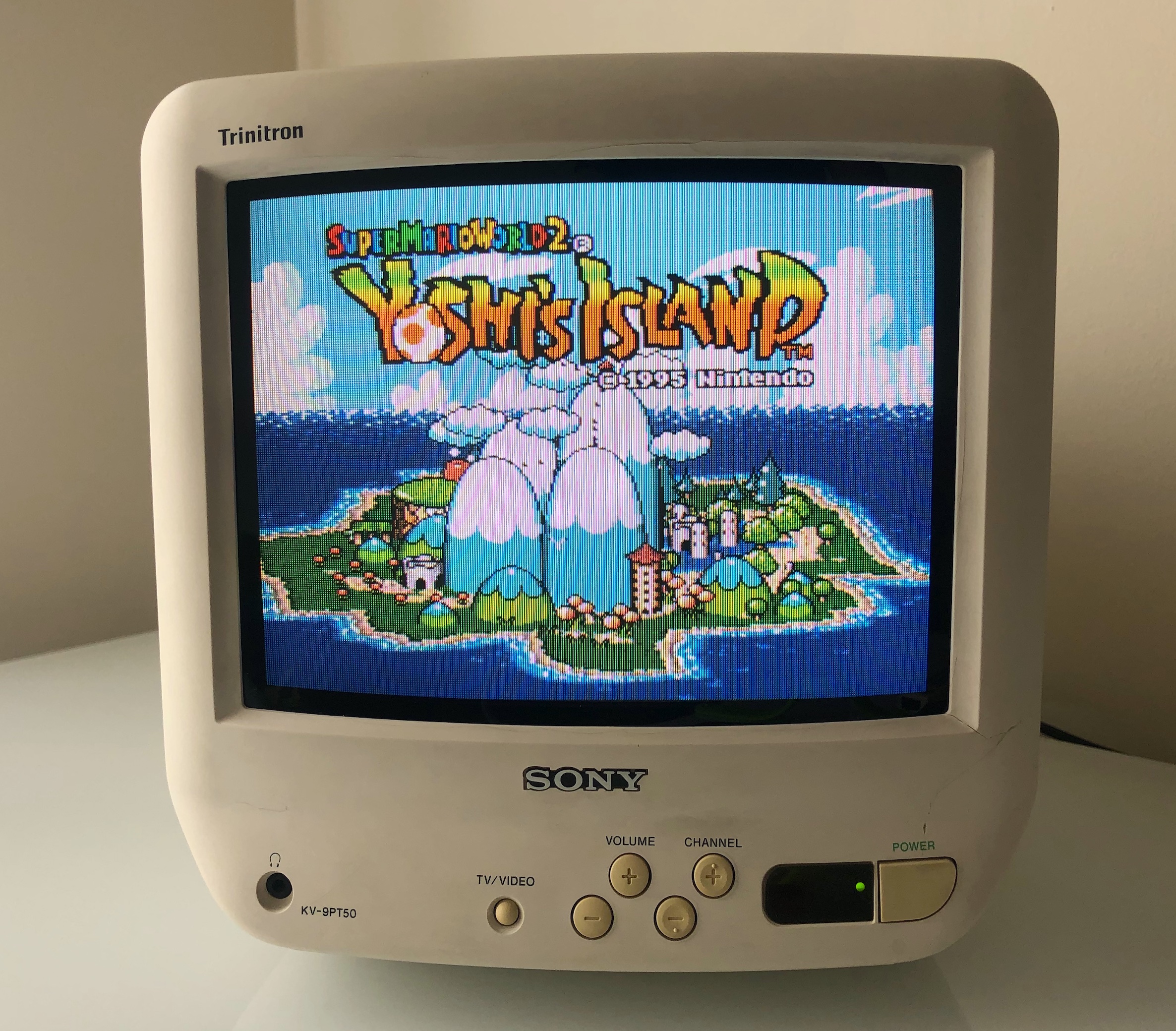
SNES - Super Mario World 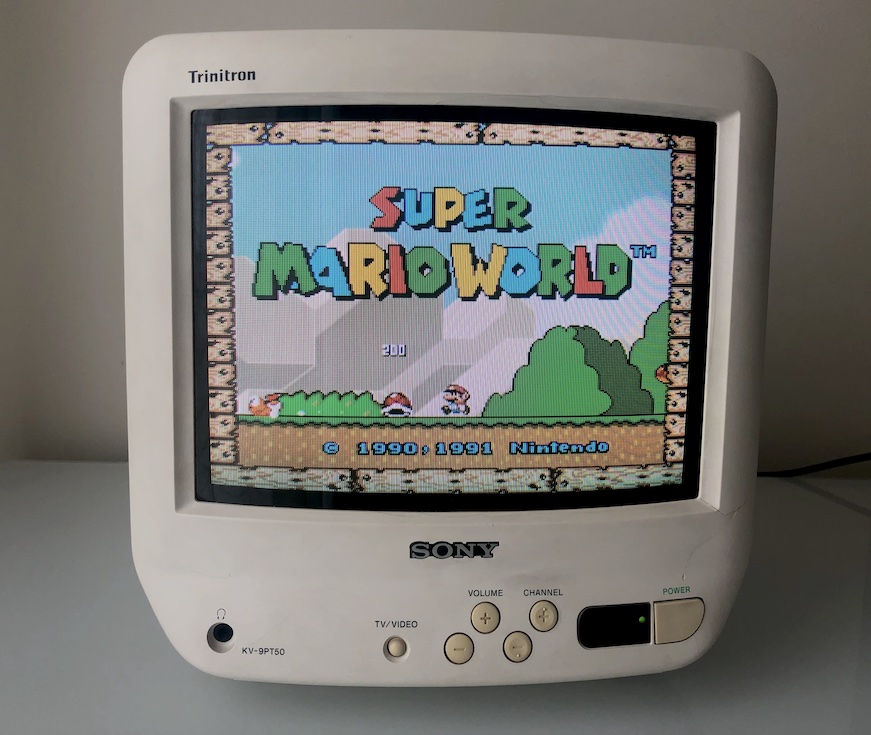
Patterns
Grid 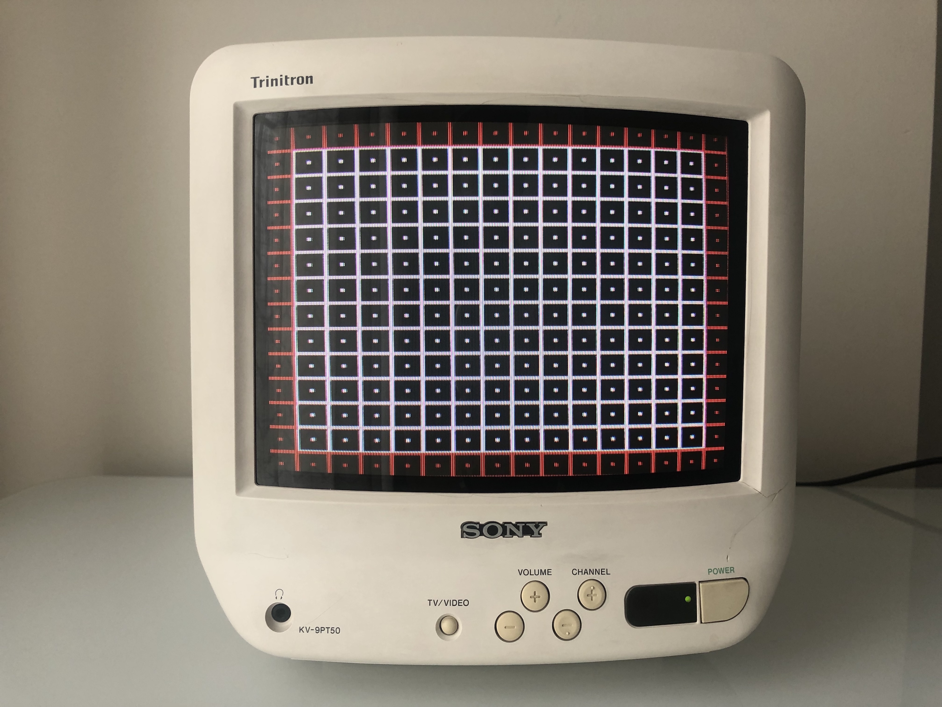
Monoscope 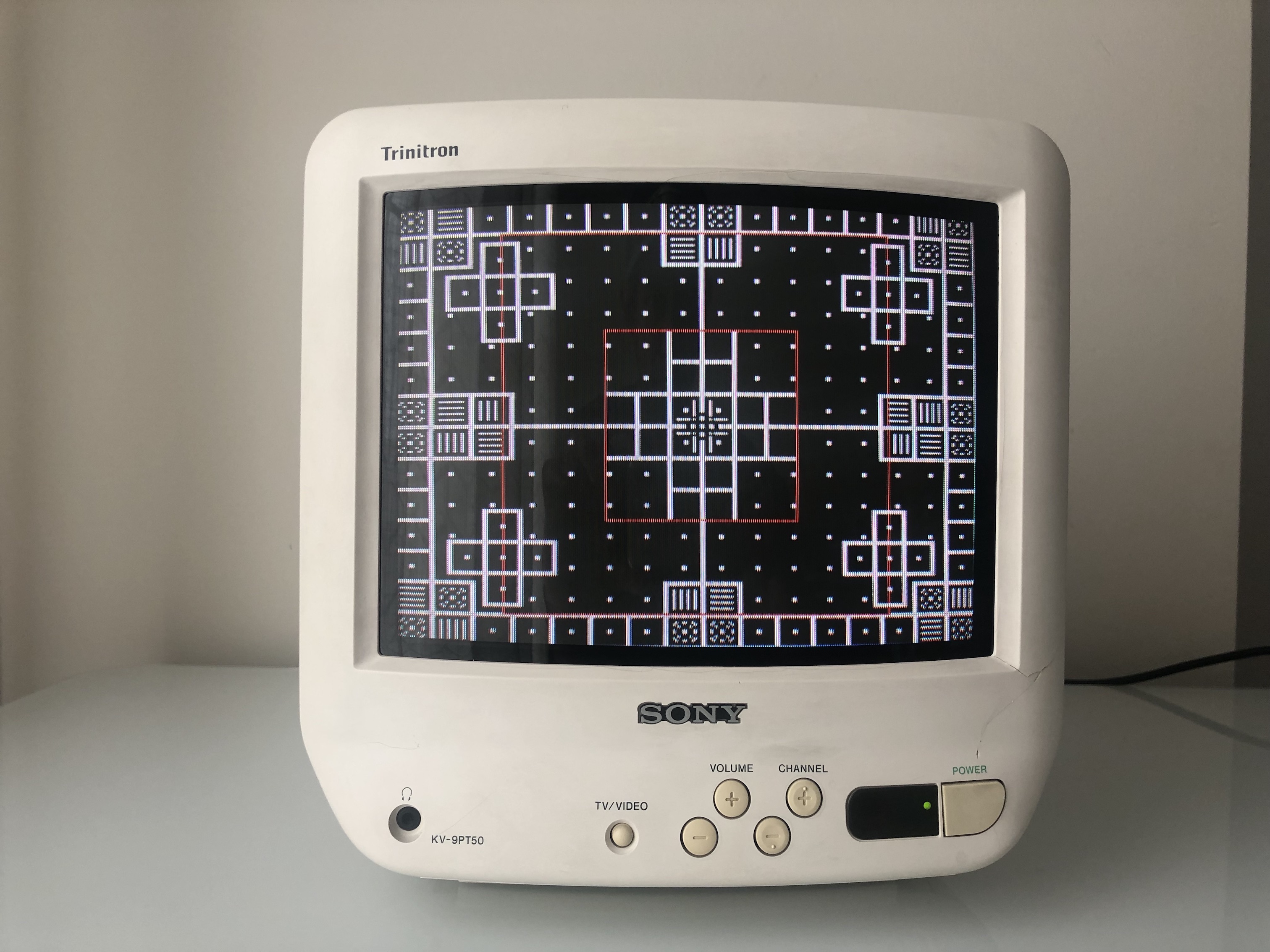
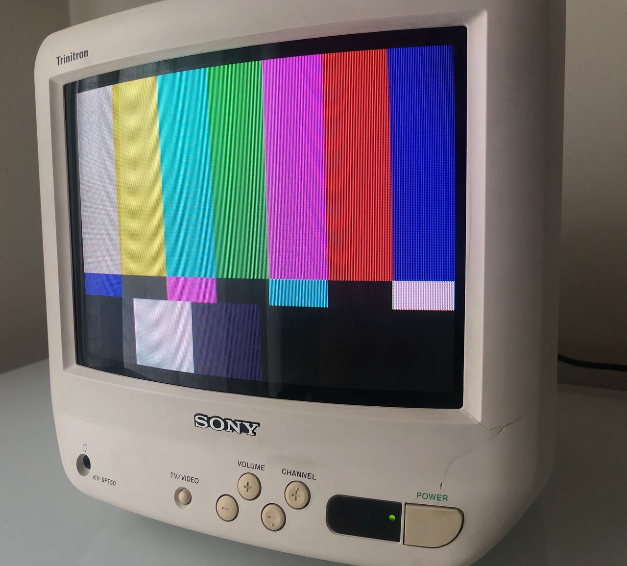
SMPTE 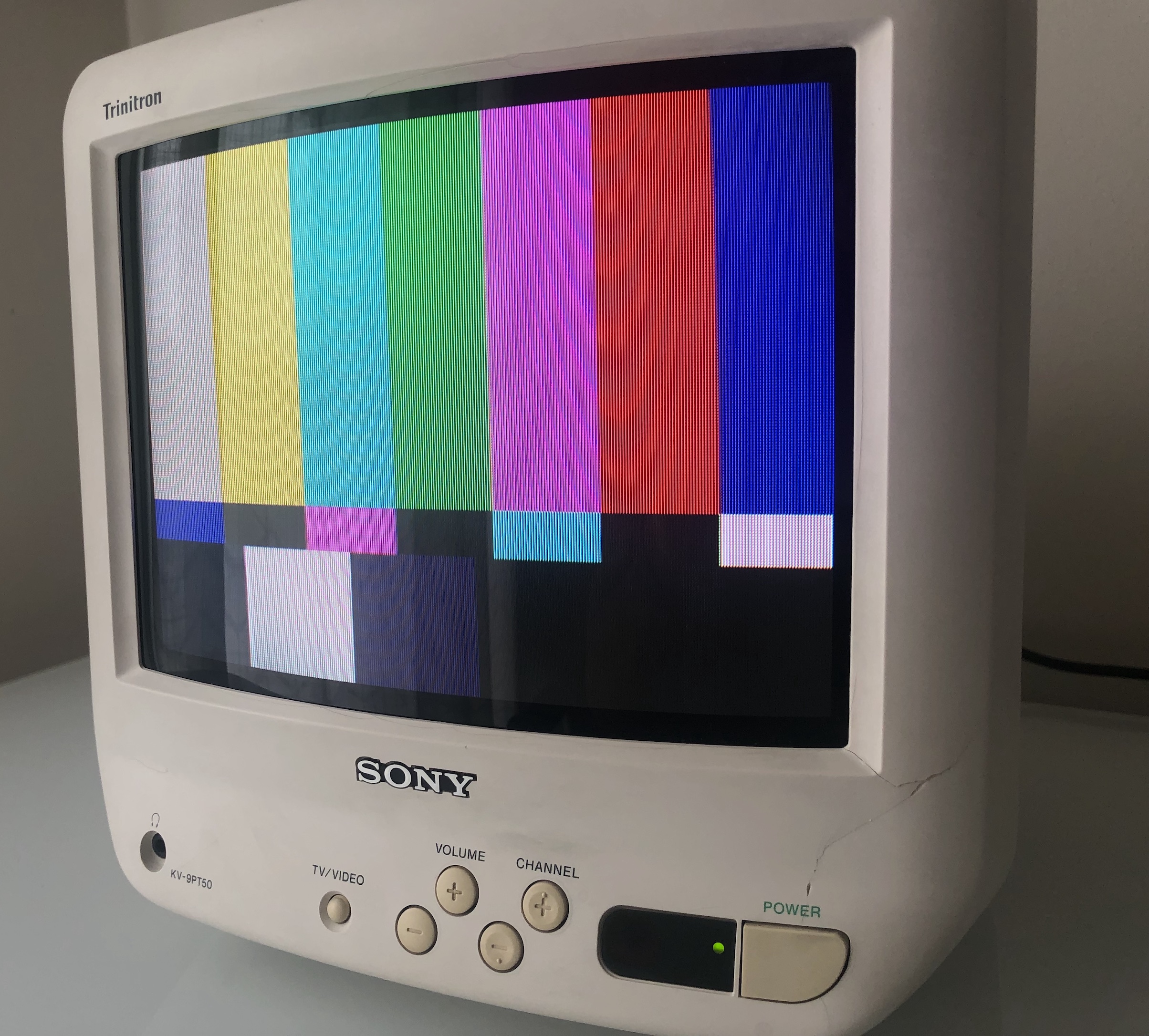
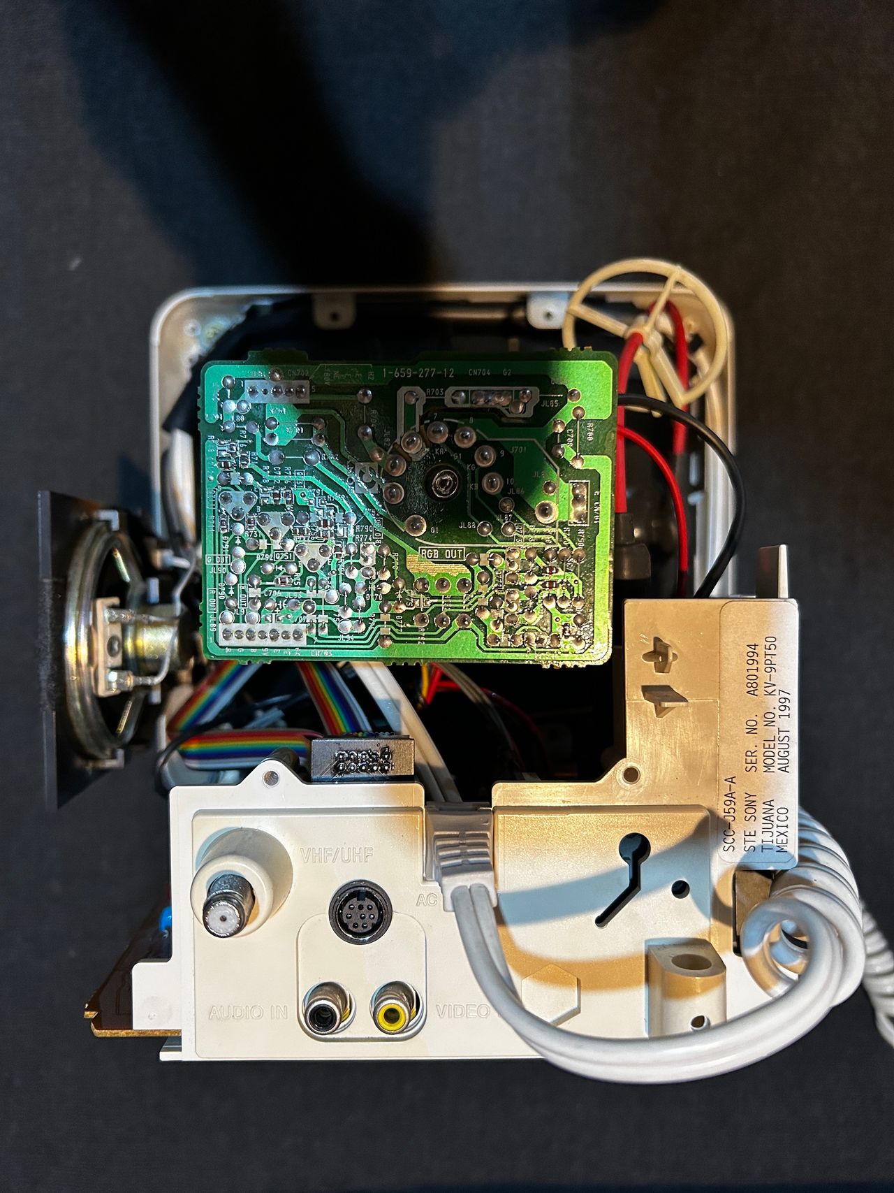
Inside of the CRT
A board 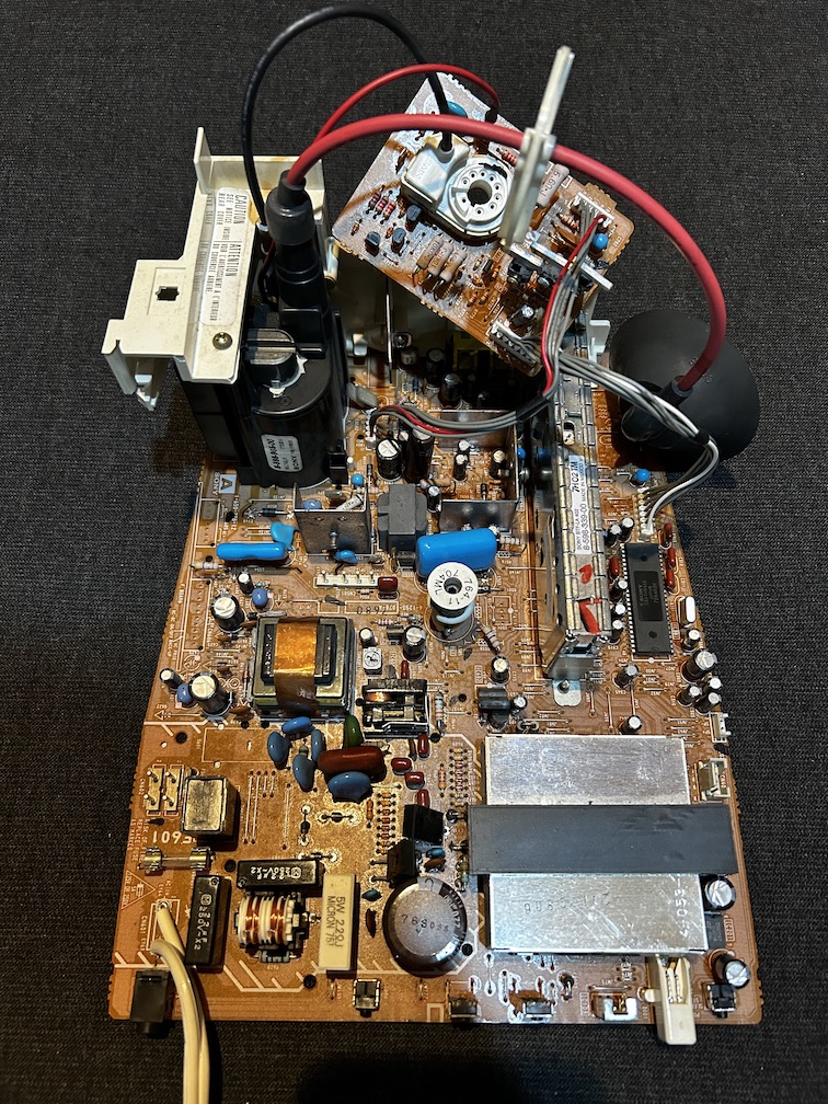
Chroma IC 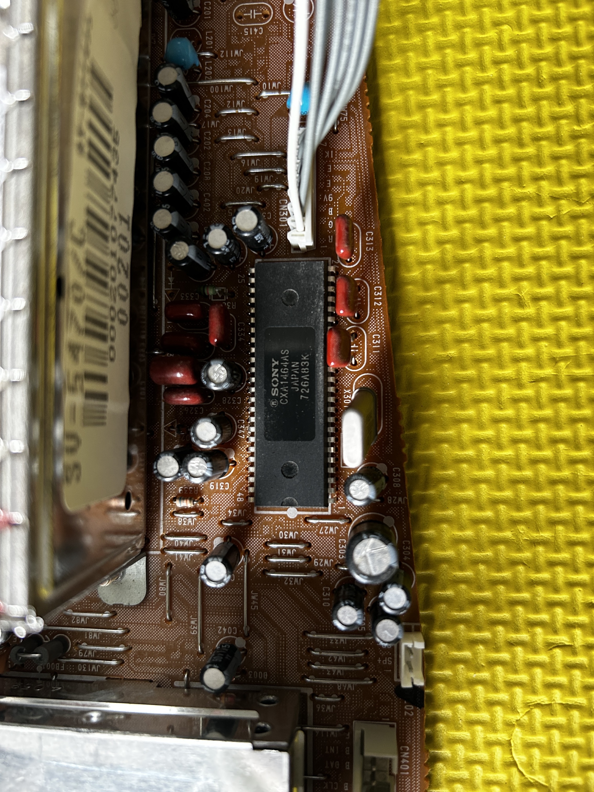
Flyback 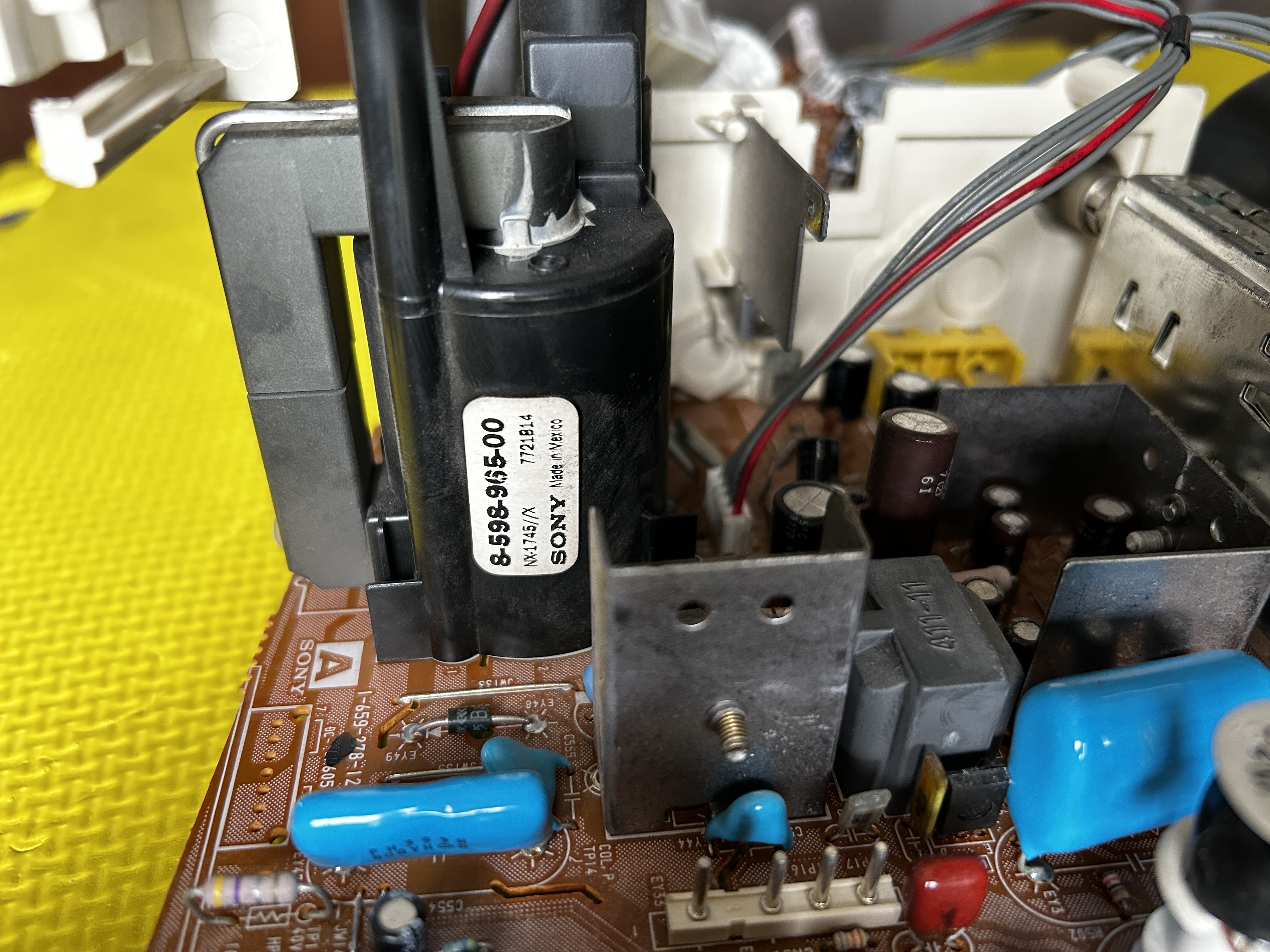
Front buttons 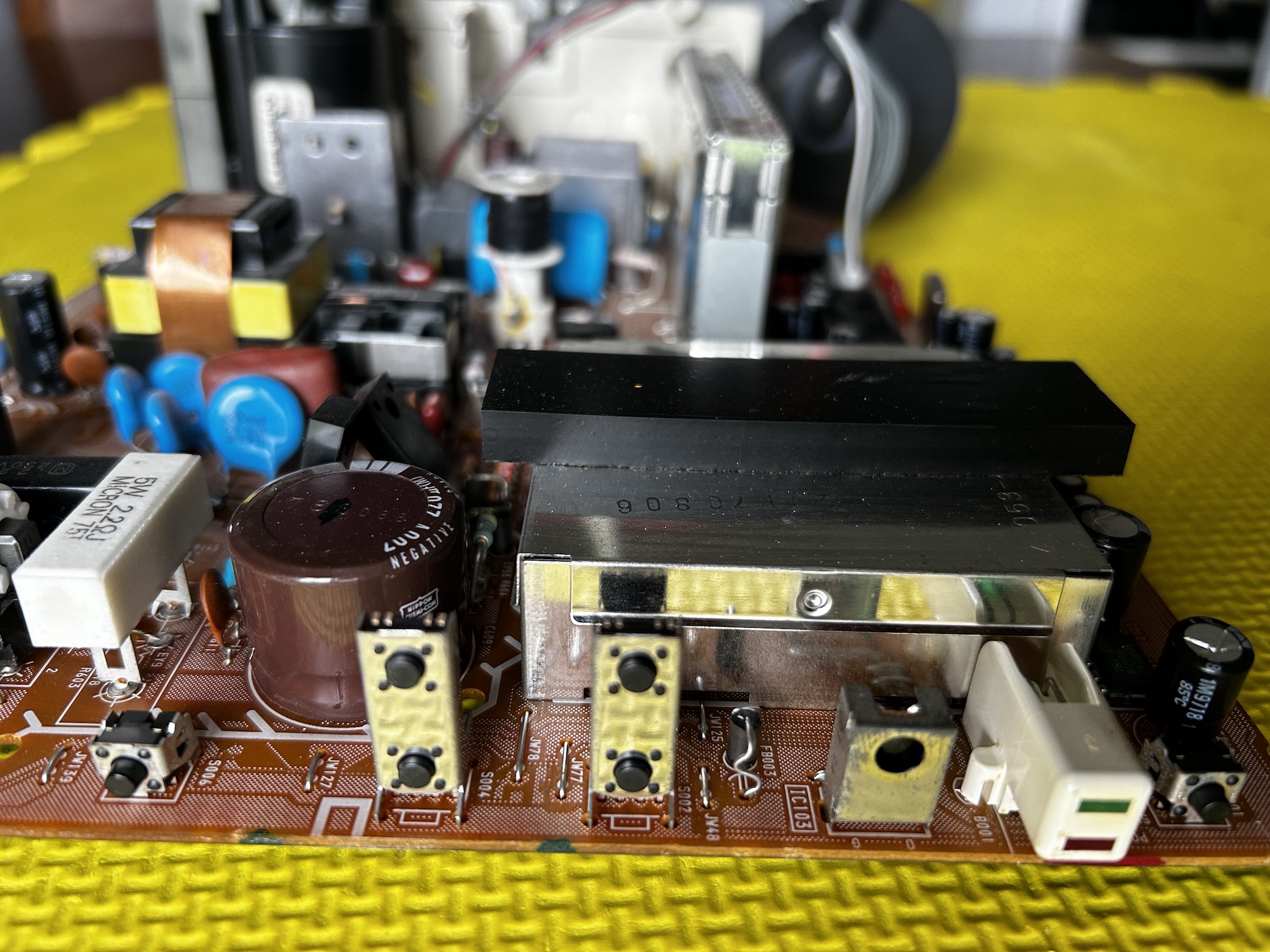
Back view
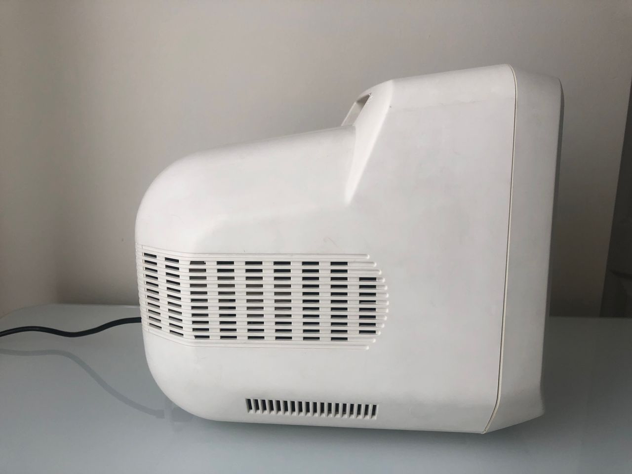
Side view 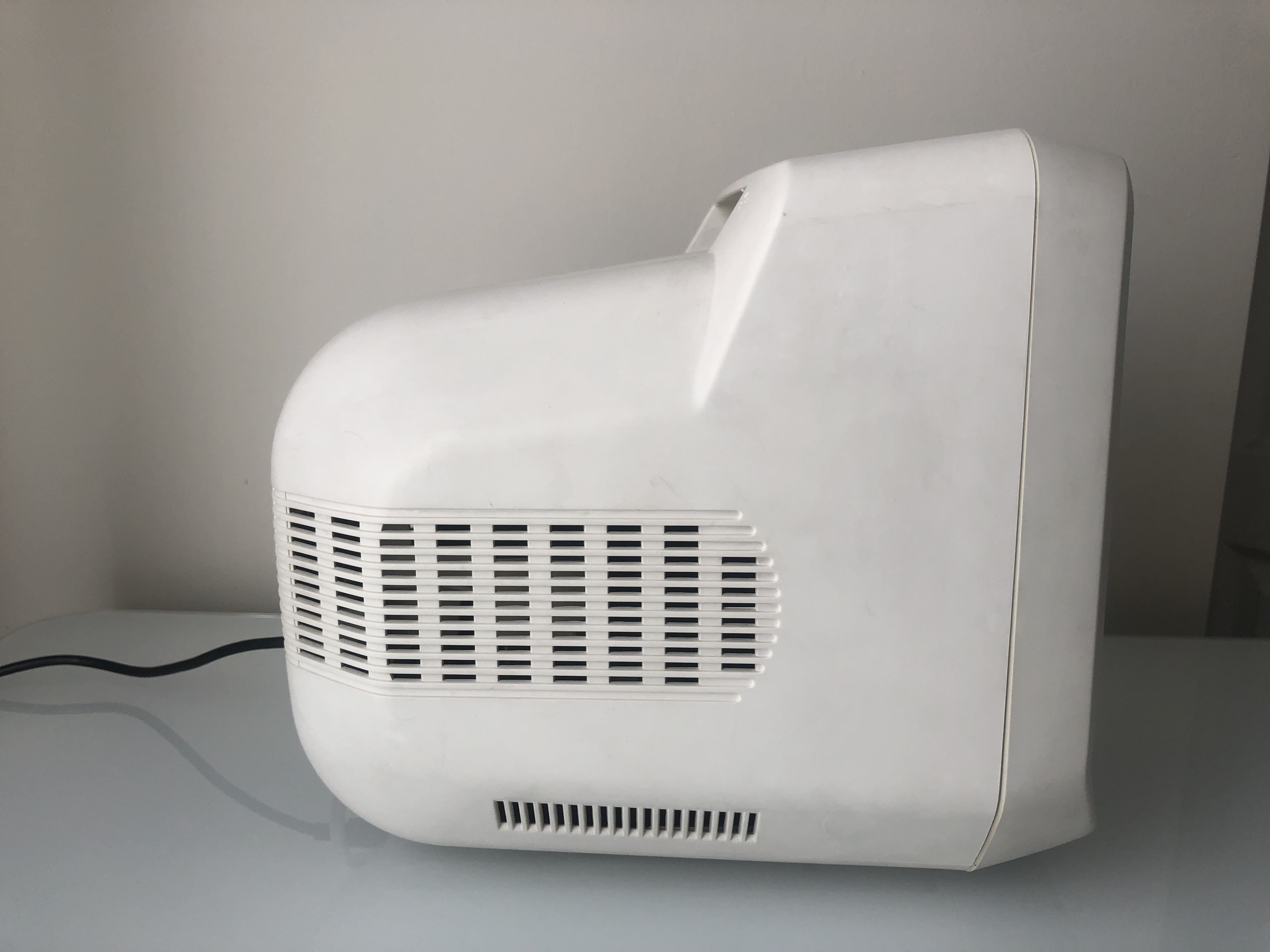
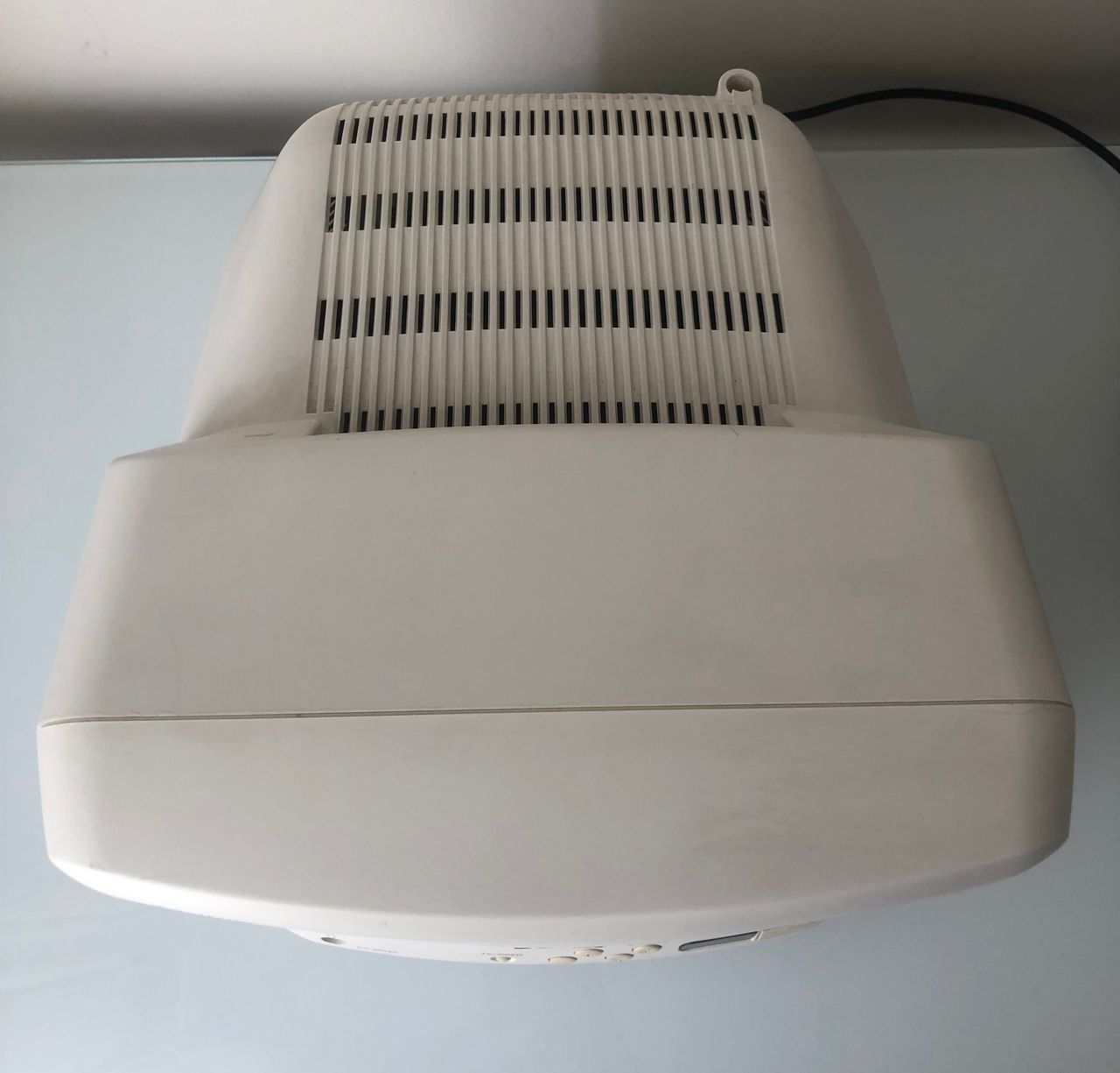
Top view 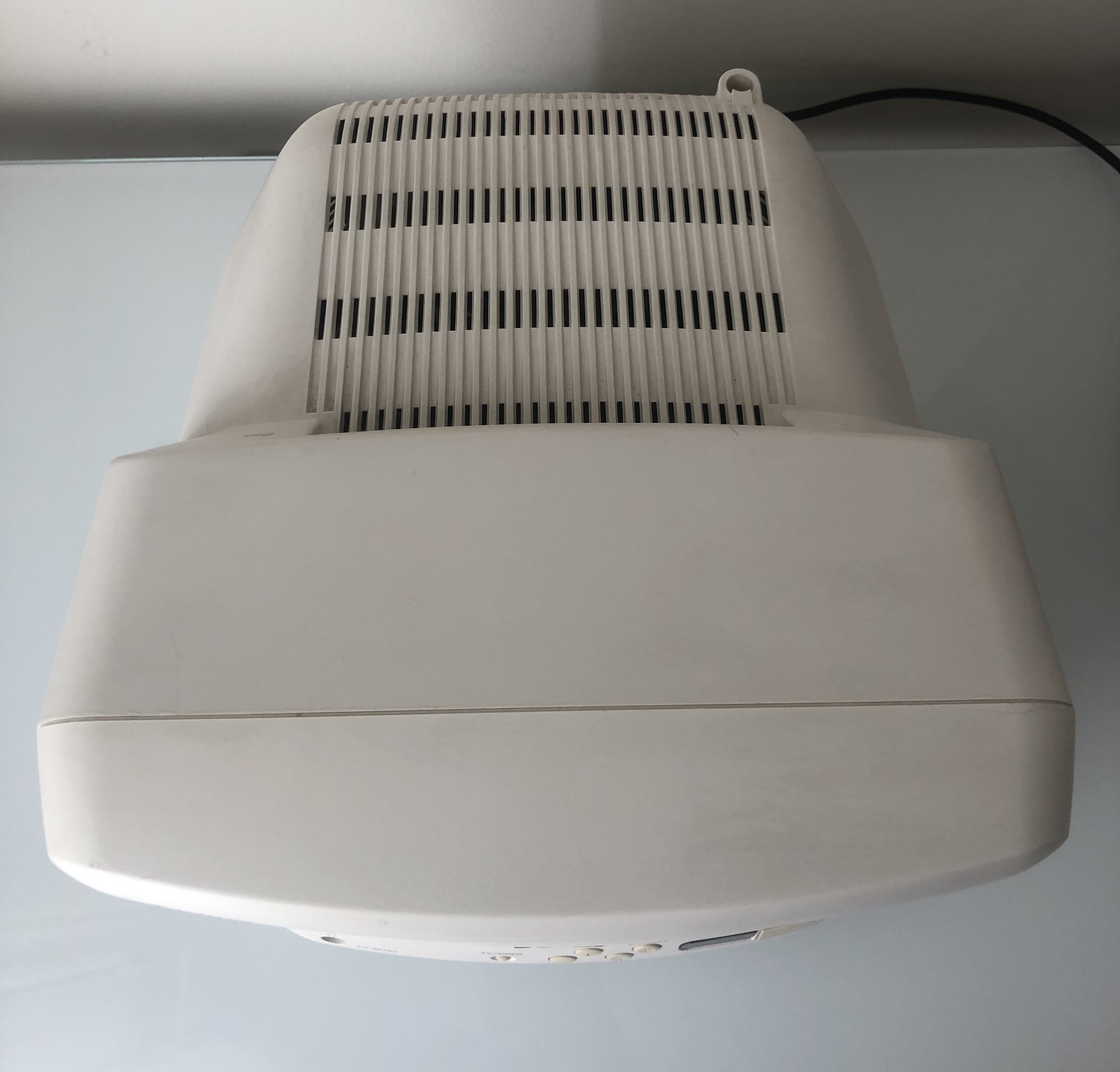
Neck board 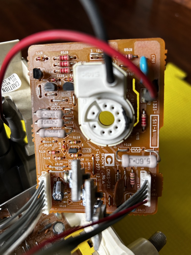
Service Menu
On the remote, press keys in this sequence DISPLAY, 5, VOL +, POWER
1 and 4 to select 3 and 6 to adjust
MUTING, ENTER to write to memory.
| NUM | SETTING | VALUE | CHANGED |
|---|---|---|---|
| 1 | AFC | 0 | DEFAULT |
| 2 | HFRE | 71 | DEFAULT |
| 3 | VFRE | 10 | DEFAULT |
| 4 | VPOS | 20 | DEFAULT |
| 5 | VSIZ | 35 | DEFAULT |
| 6 | VLIN | 7 | DEFAULT |
| 7 | VSCO | 4 | DEFAULT |
| 8 | HPOS | 14 | 12 |
| 9 | HSIZ | 14 | DEFAULT |
| 10 | PAMP | 15 | DEFAULT |
| 11 | CPIN | 4 | DEFAULT |
| 12 | PPHA | 7 | DEFAULT |
| 13 | VOM | 2 | DEFAULT |
| 14 | GAMP | 11 | DEFAULT |
| 15 | BAMP | 9 | DEFAULT |
| 16 | GCUT | 9 | DEFAULT |
| 17 | BCUT | 10 | DEFAULT |
| 18 | CROM | 30 | DEFAULT |
| 19 | SPIX | 15 | DEFAULT |
| 20 | SHUE | 26 | DEFAULT |
| 21 | SCOL | 29 | DEFAULT |
| 22 | SBRT | 35 | 33 |
| 23 | RGBP | 31 | DEFAULT |
| 24 | SHAP | 9 | DEFAULT |
| 25 | VSMO | 0 | DEFAULT |
| 26 | REF | 1 | DEFAULT |
| 27 | ROFF | 1 | DEFAULT |
| 28 | GOFF | 1 | DEFAULT |
| 29 | BOFF | 1 | DEFAULT |
| 30 | ABLM | 0 | DEFAULT |
| 31 | NOTC | 0 | DEFAULT |
| 32 | DRGB | 0 | DEFAULT |
| 33 | DISP | 7 | DEFAULT |
| 34 | SPOT | 8 | DEFAULT |
| 35 | PBLK | 13 | DEFAULT |
Pictures
Photos by Sunthar

Reference Photos