Sony (BA-5) KV-20FV12
Sony (BA-5) KV-20FV12 CRT RGB mod
The Sony KV-20FV12 is a 20" Flat Trinitron WEGA CRT TV known for superior 240p/480i picture quality. Released around 2002–2003, this flat-screen set features S-Video/composite inputs.
This set can be modified for RGB input.
View full CRT details and more mod examples →
Contributors
Thank you to everyone who contributed to this guide:
- Dan Lavoie — showcase author
- Wei Lin — showcase author
- Mike Morisette — contributor, CRT specs from CRT Database.
CRT safety
Caution
You can die doing this! So read carefully! CRT TV is not a toy. Do not open a CRT TV. If you don't have any prior knowledge about handling high voltage devices, this guide is not for you. CRT TV contains high enough voltage (20,000+ V) and current to be deadly, even when it is turned off.
Plan of attack
Manuals and Datasheets
Specs
- Year: 2000
- Format: NTSC
- Chassis: BA-5
- Tube: Sony Trinitron A51LPT70X
- Jungle Chip: Sony CXA2131AS
- OSD Chip: M37273MF-258SP
- Screen Size: 20"
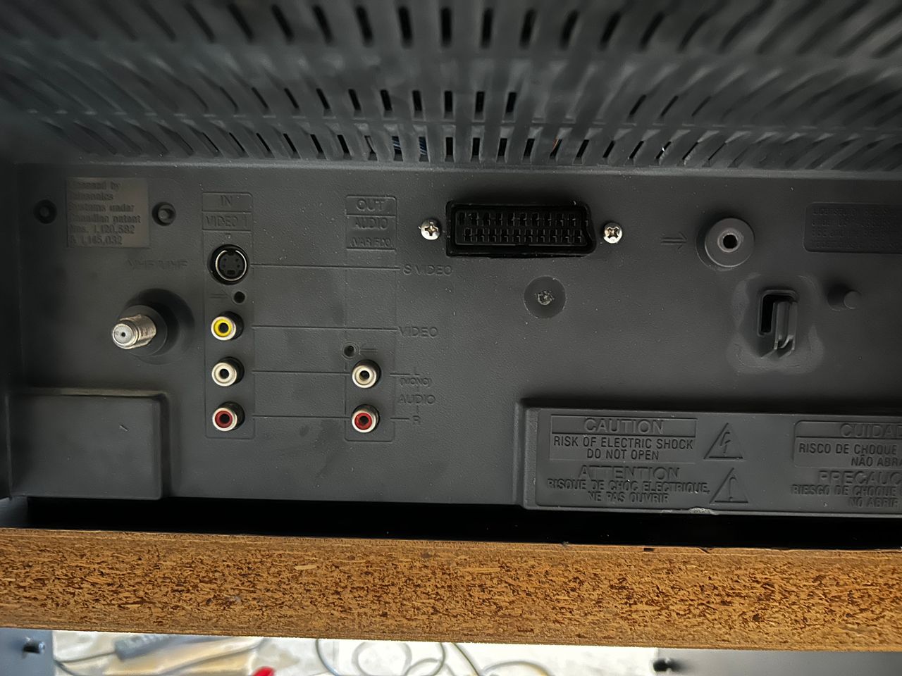
- Inputs: Composite, S-Video, RF
Schematics
Please note there is a second RGB input available in CXA2131CS. However, it is disabled in software. You can activate it by using I2C as documneted here. However, it is more effort than just doing a mux mod.
Calculating the RGB external resistor value
Formula from our theory page!

RGB external resistor value = 0.7 x (6800 + 75) - (75 x 5) / (5 - 0.7) = (4812 - 375) / 4.3 = 1030 ohm
~ 1 Kohm resistors should do the job.
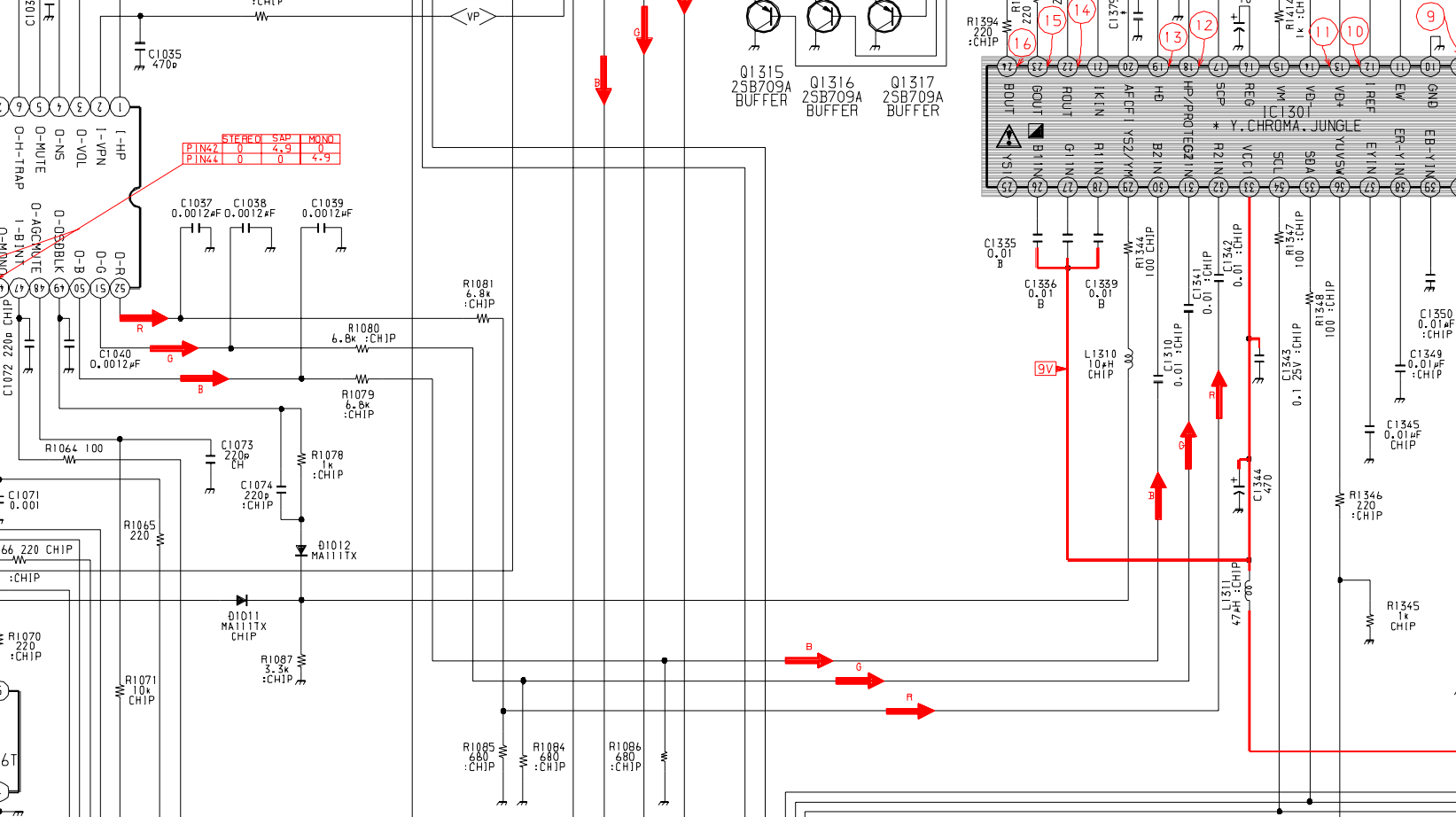
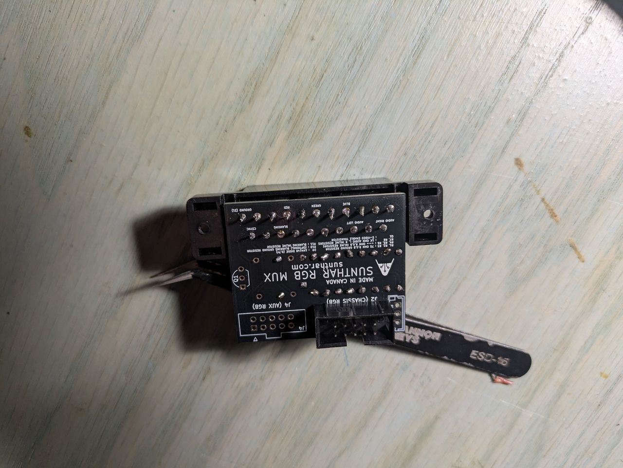
RGB mux diagram
Prepare the mux diagram. If you are building your own circuit, this diagram should help.
Performing the mod
Now that you roughly know what needs to be done, prepare for the mod. Place the board on a comfortable place. Make sure you are not putting pressure on the flyback or other components.
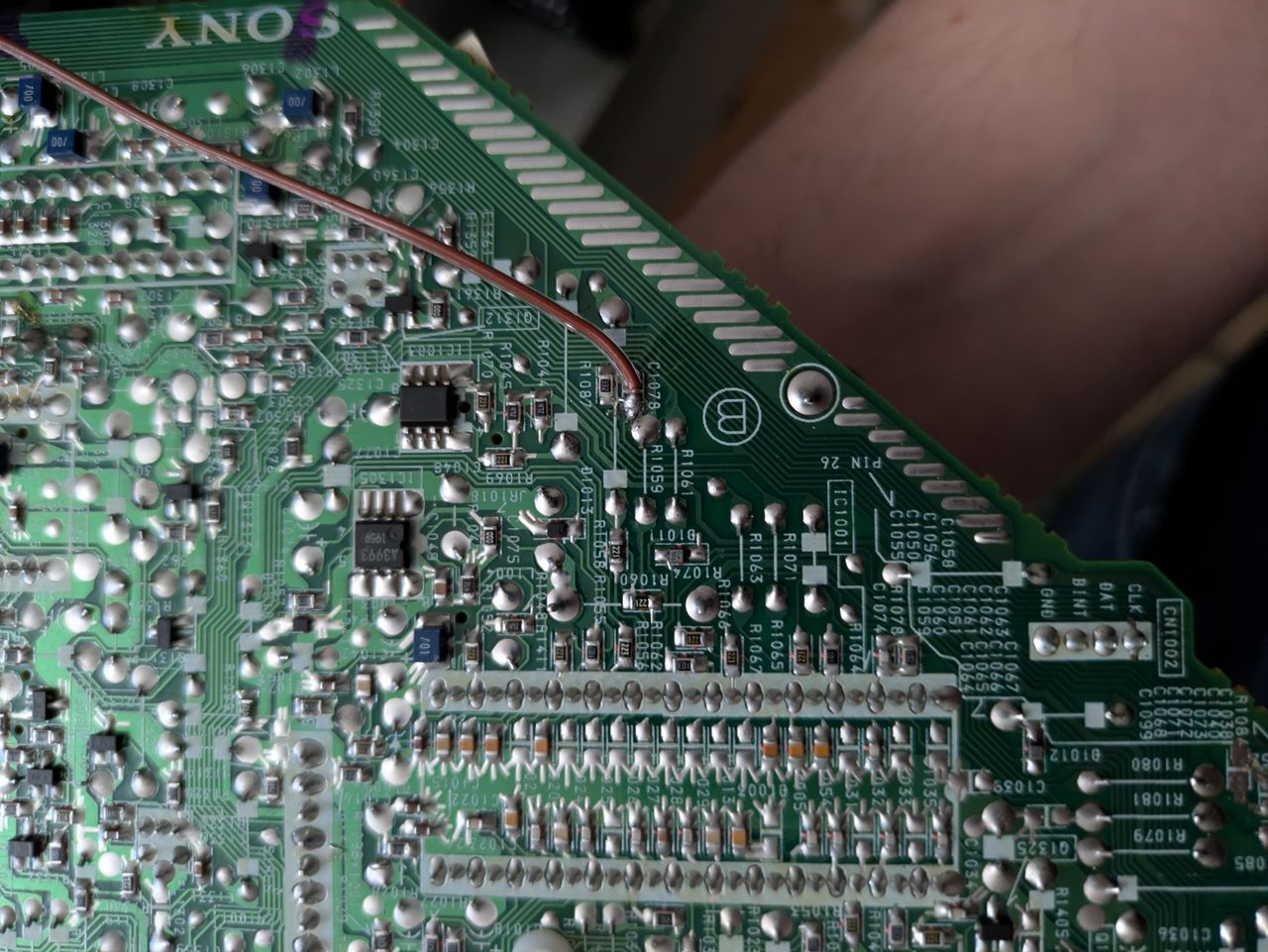
STEP 1: Remove the following components
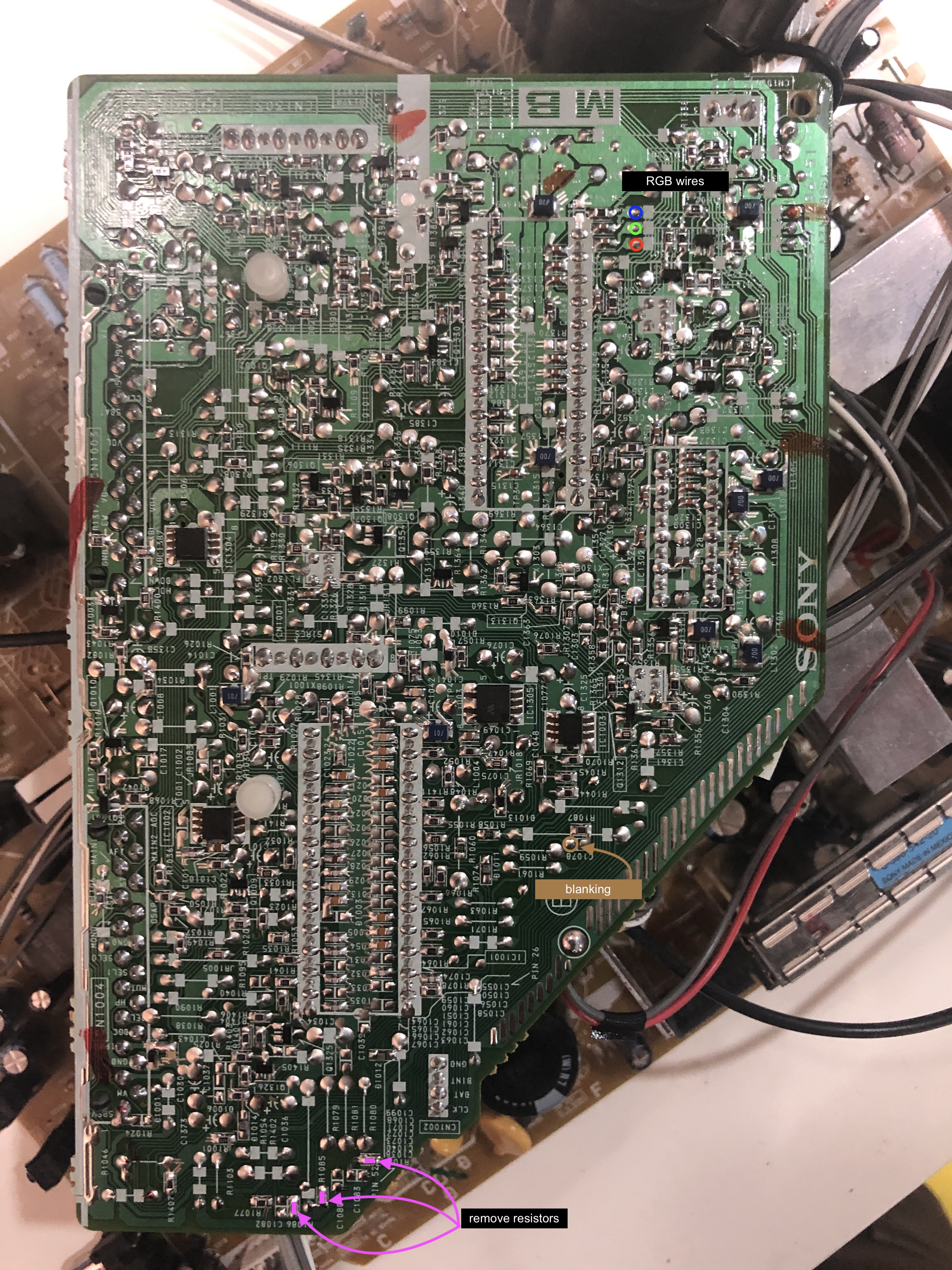
Remove the following components. RGB resistors to the ground. Measure twice and mark before you remove.
- R1084 (680Ω)
- R1085 (680Ω)
- R1086 (680Ω)
Note: there can be slight differences in the board layout. I have seen slightly different MB board layout, even within the same 20FV12 CRTs.
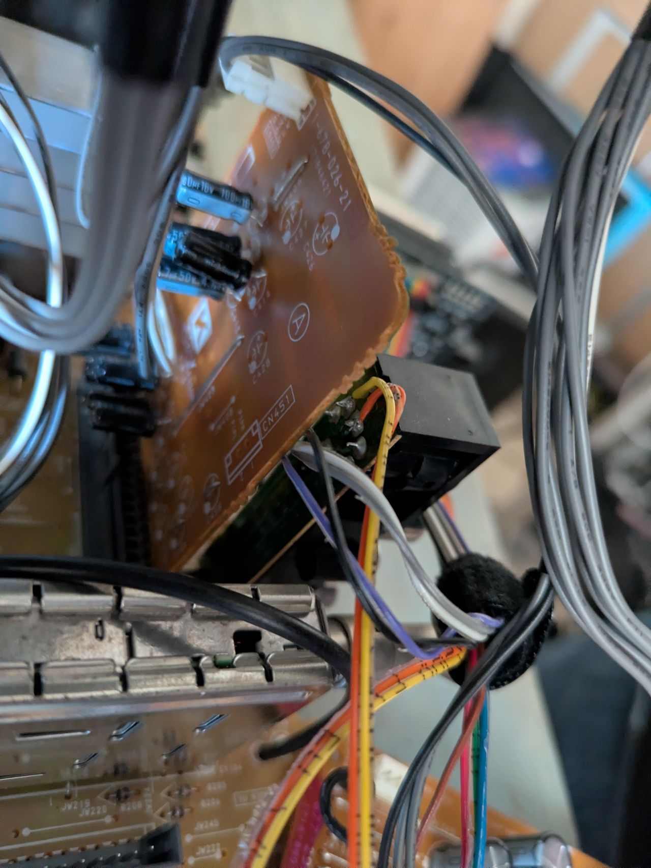
STEP 2: Connect RGBs, Blanking and Audio
See picture above to see where blanking should be connected.
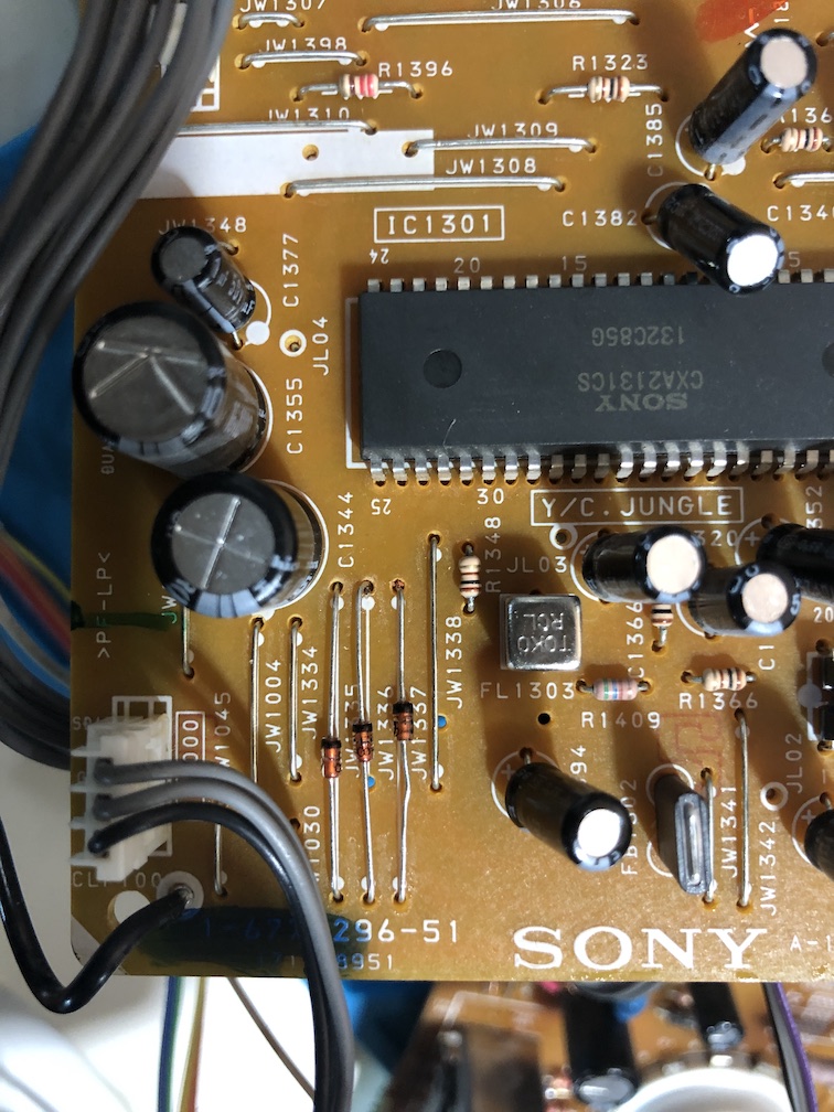
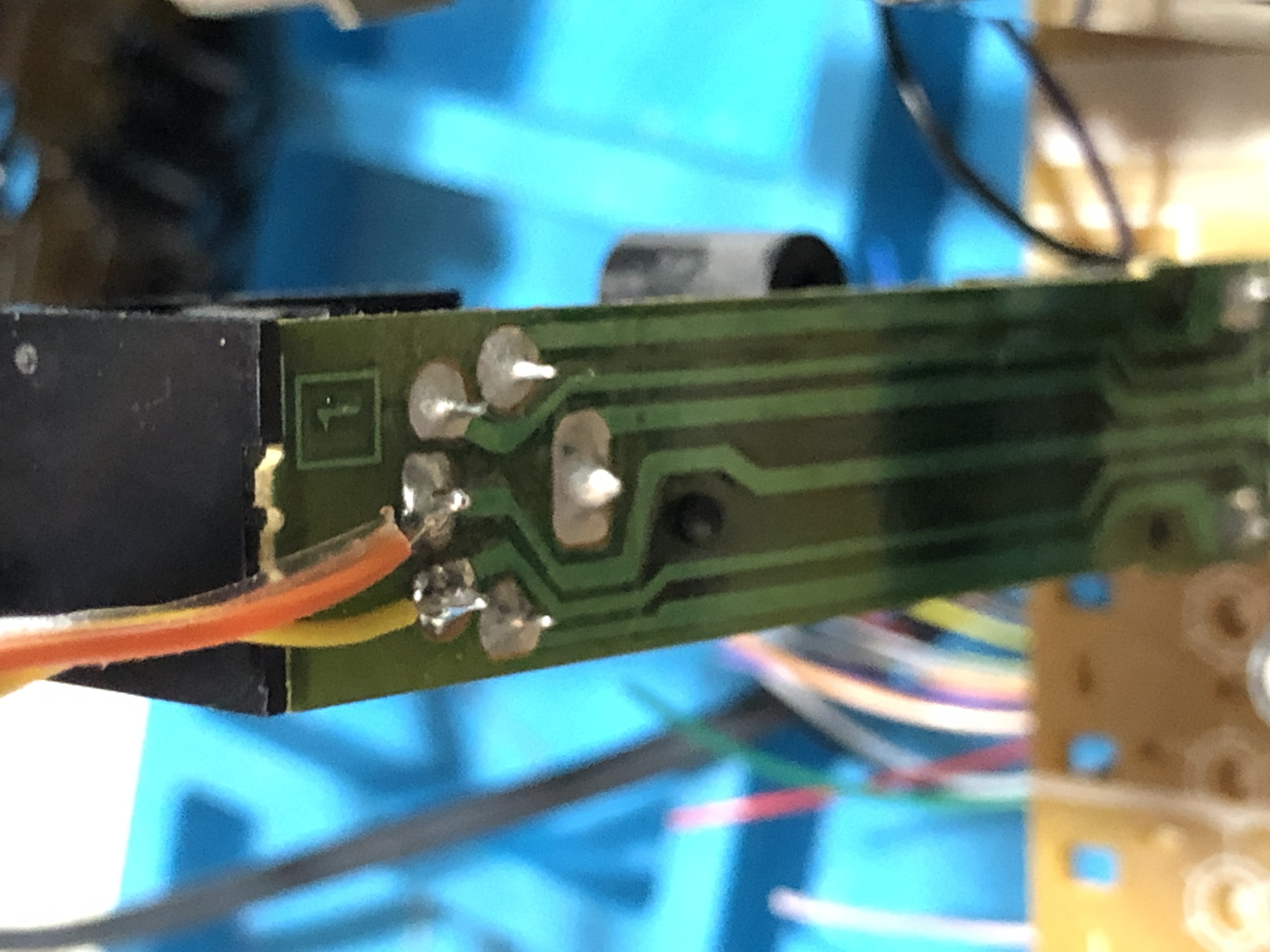
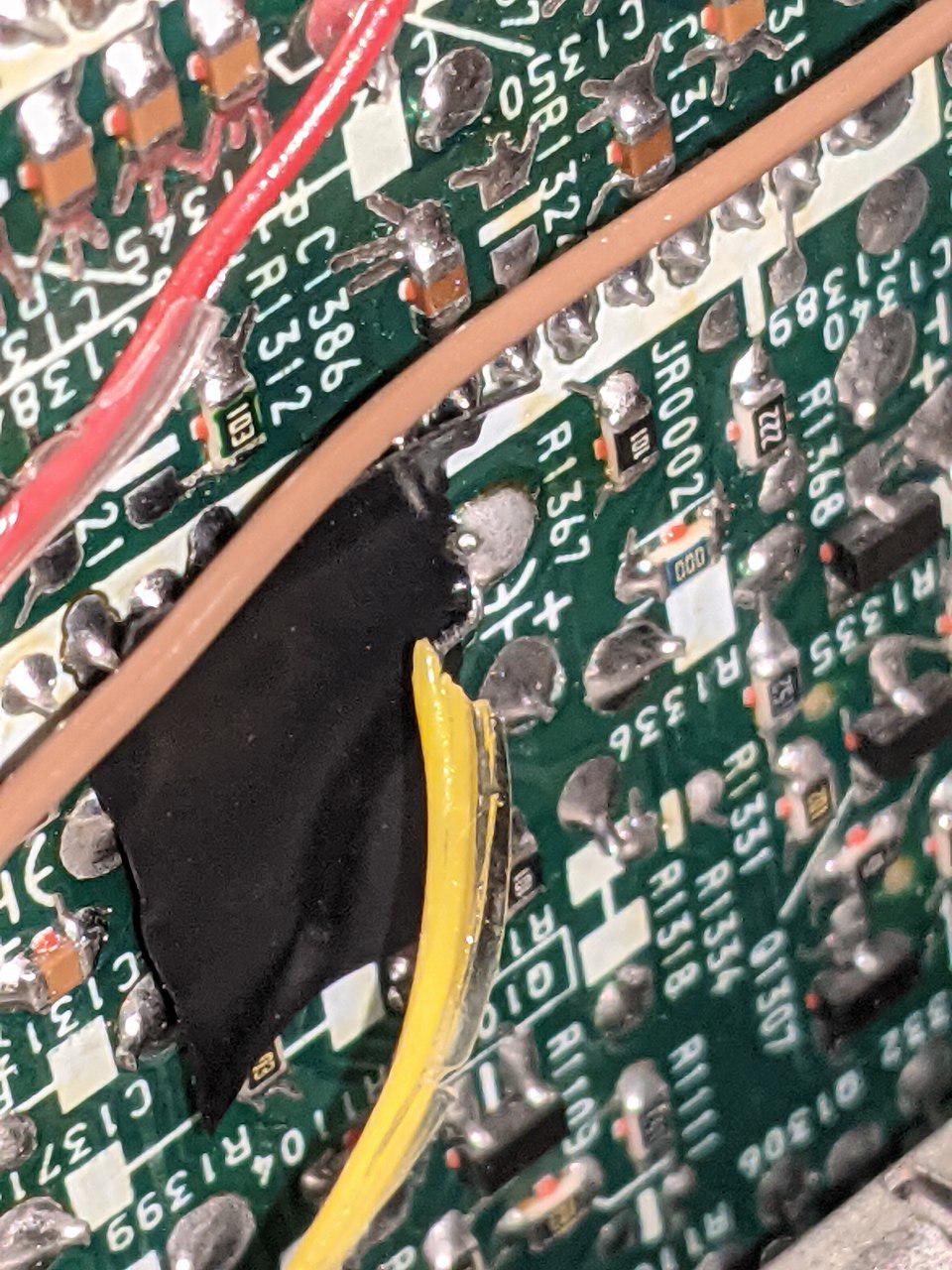
Let's remove the jumpers JW1335, JW1336, JW1337 and replace with 3 1N4148 diodes. Pay attention to the direction of the diodes. There is a black bar indicating which way the current flows. This helps reduce feedback noise and voltage going back into the OSD.
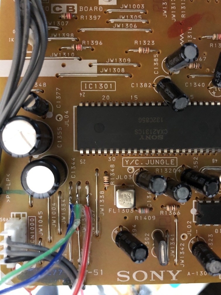
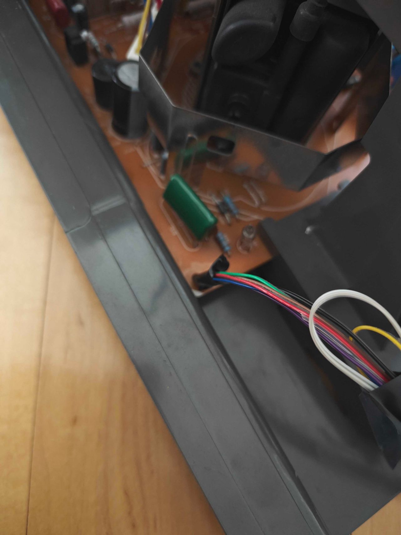
Then attach the R, G, B wires to the respective legs of the diodes. Wires should be attached to the side closer to the jungle chip.
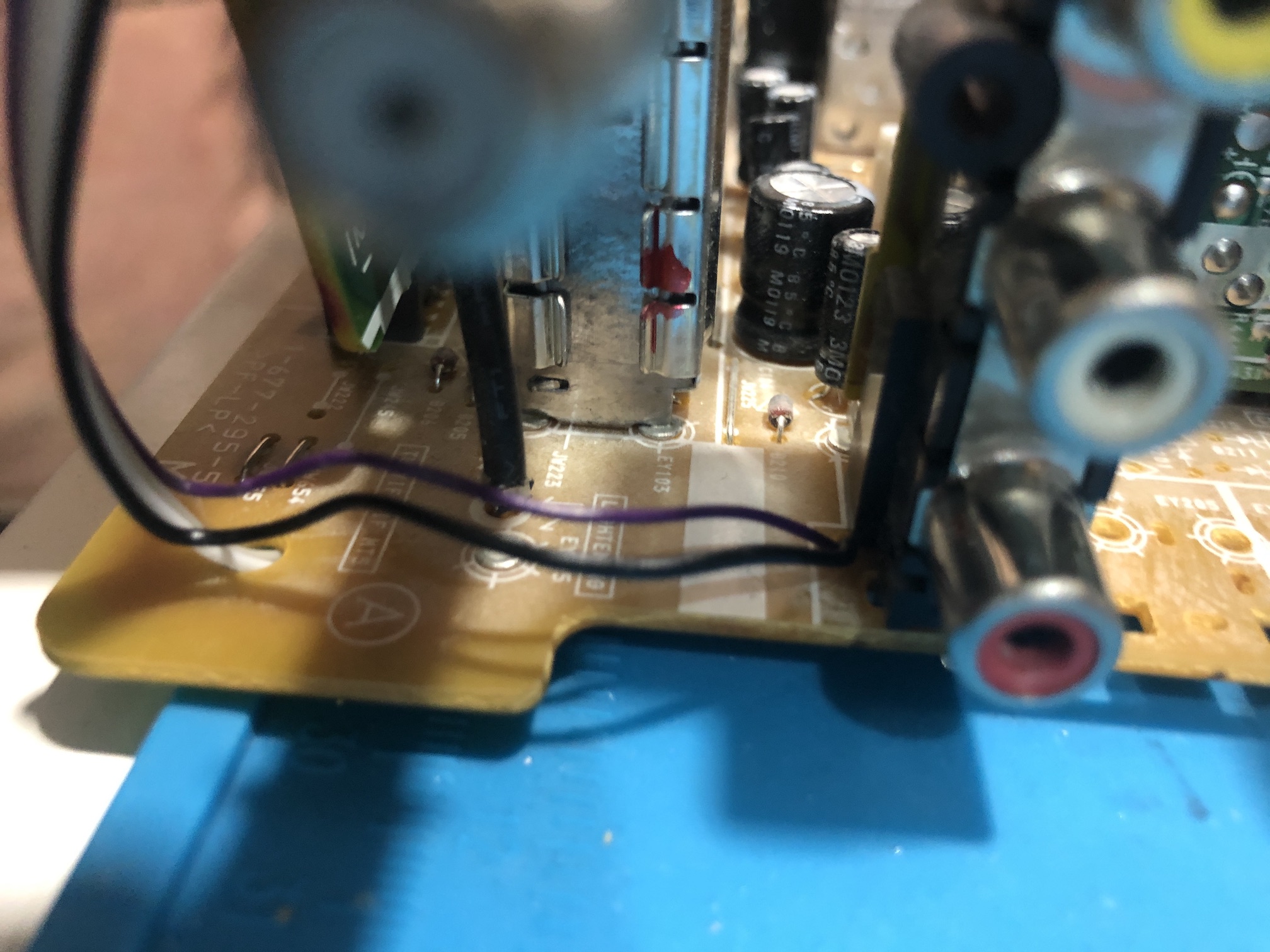
Twist the orange and yellow wires. Sync wire (yellow) should be connected directly to the s-video Y pin. Ground wire (orange) should be connected to the ground. Audio wiring can go below the board. Connect audio left (white) and audio right (grey) as seen in the pics below.
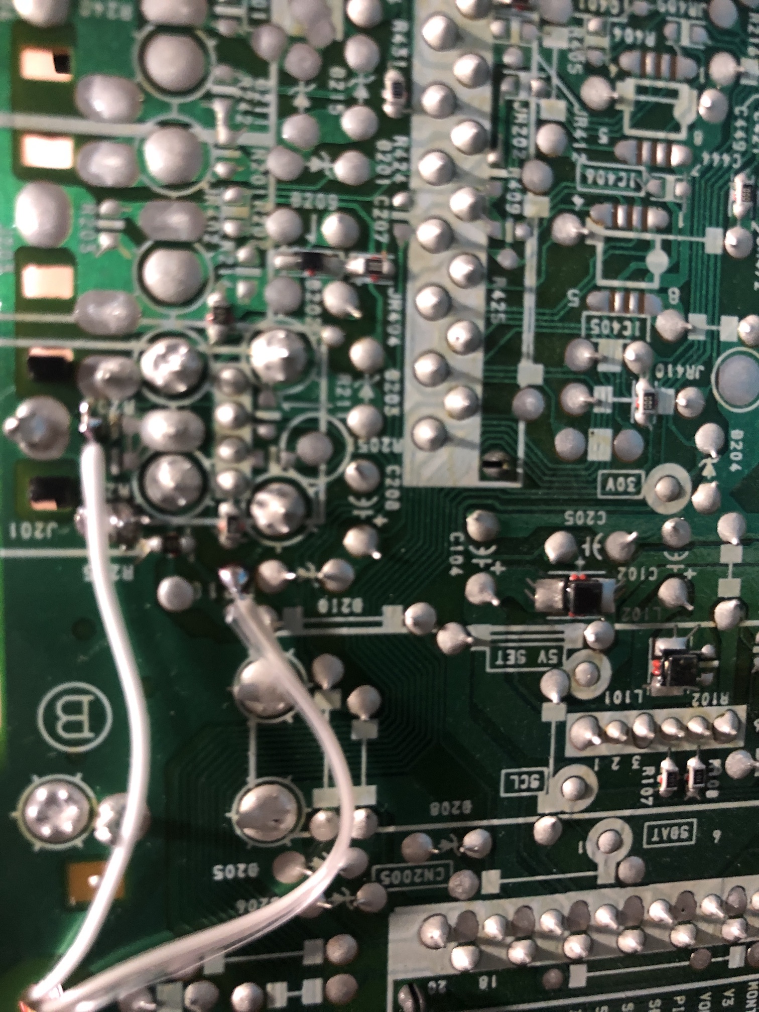
Ground both common ground (black) and audio ground (purple) wires.
STEP 2: Special instructions for KV-20FS12
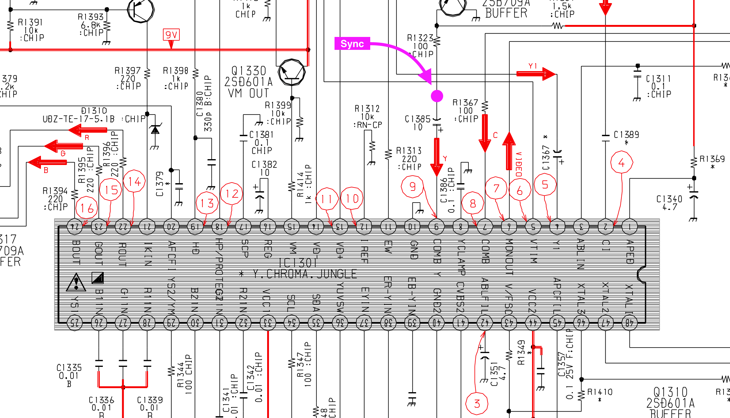
Since there is no s-video you can tap into, try feeding sync to the negative leg of C1385 capacitor. That is the COMB Y input.
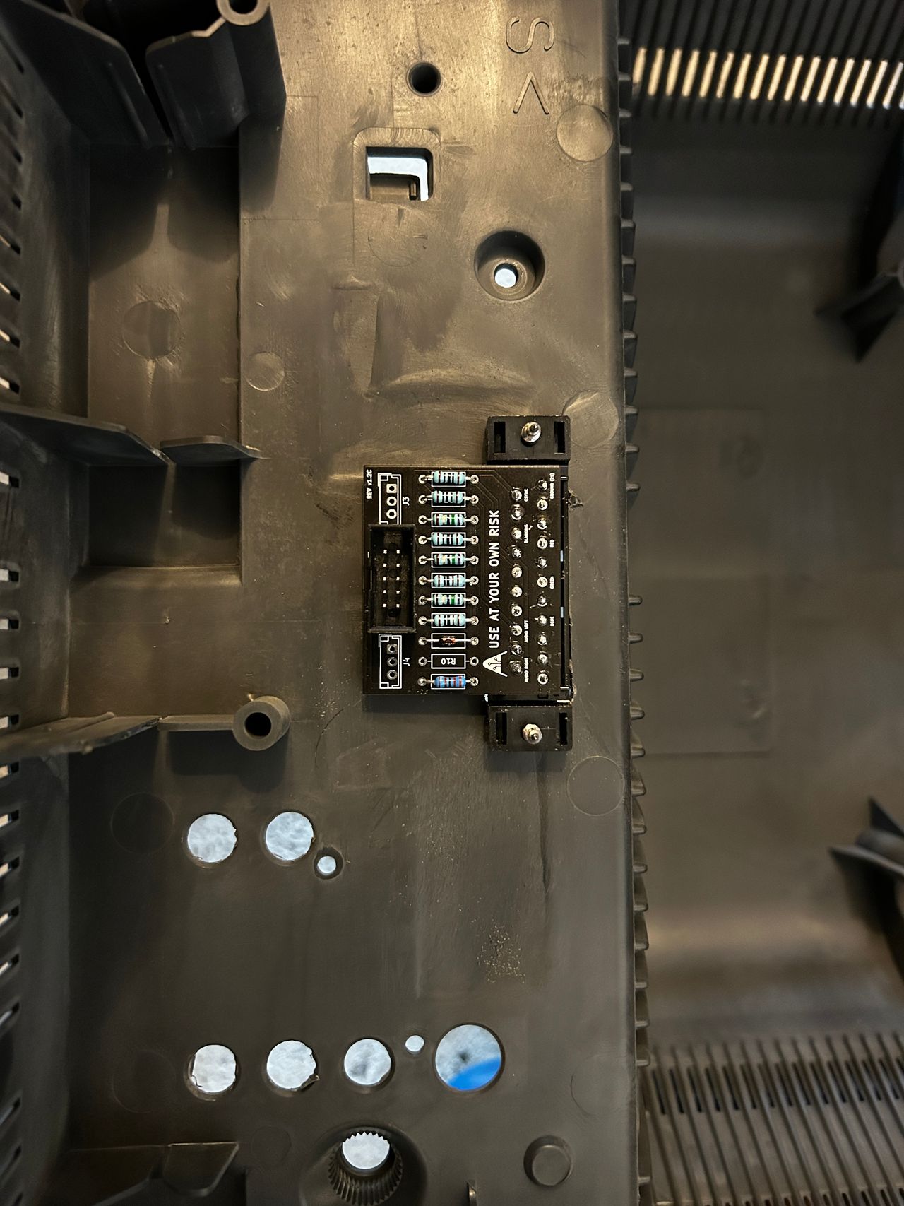
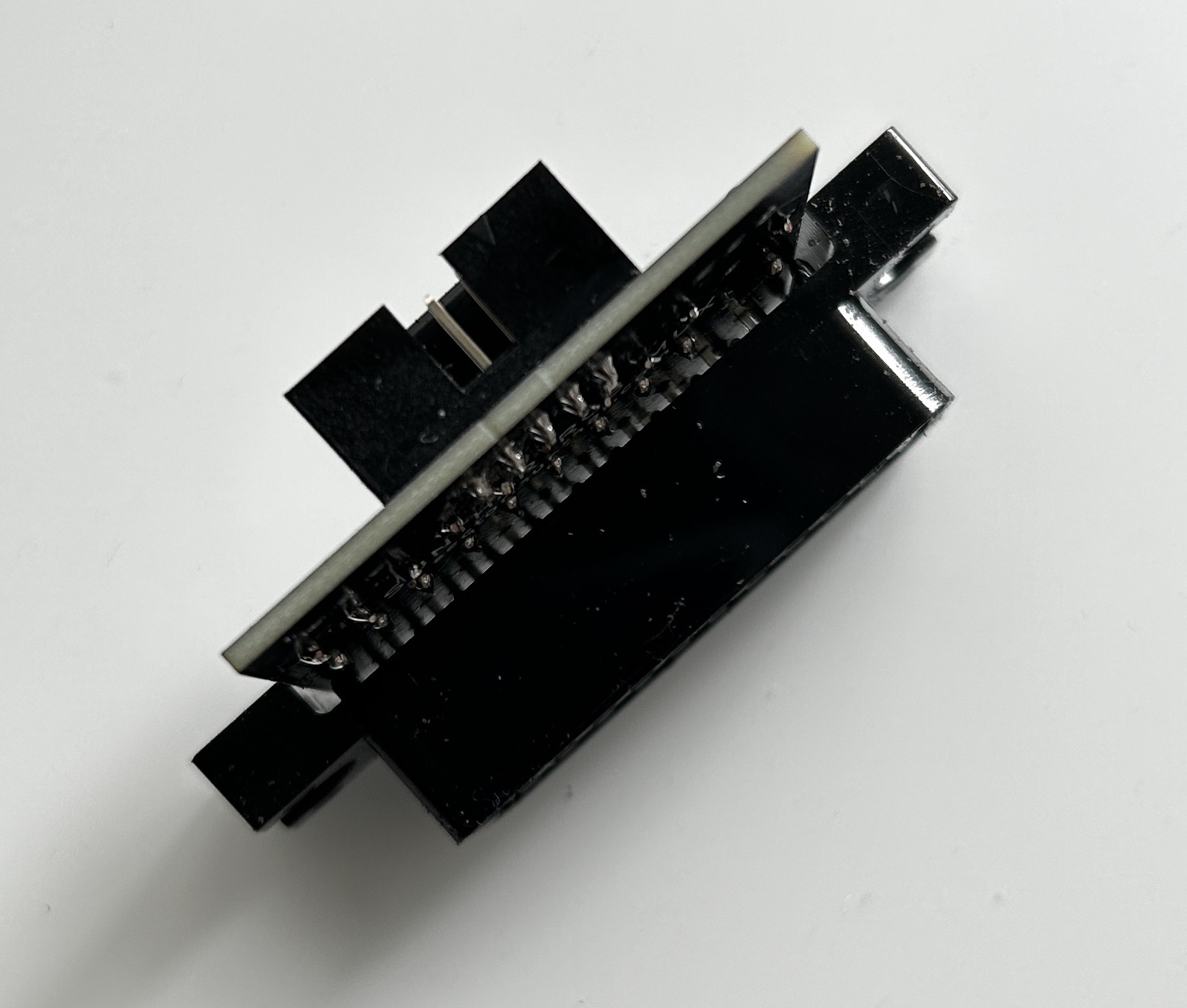
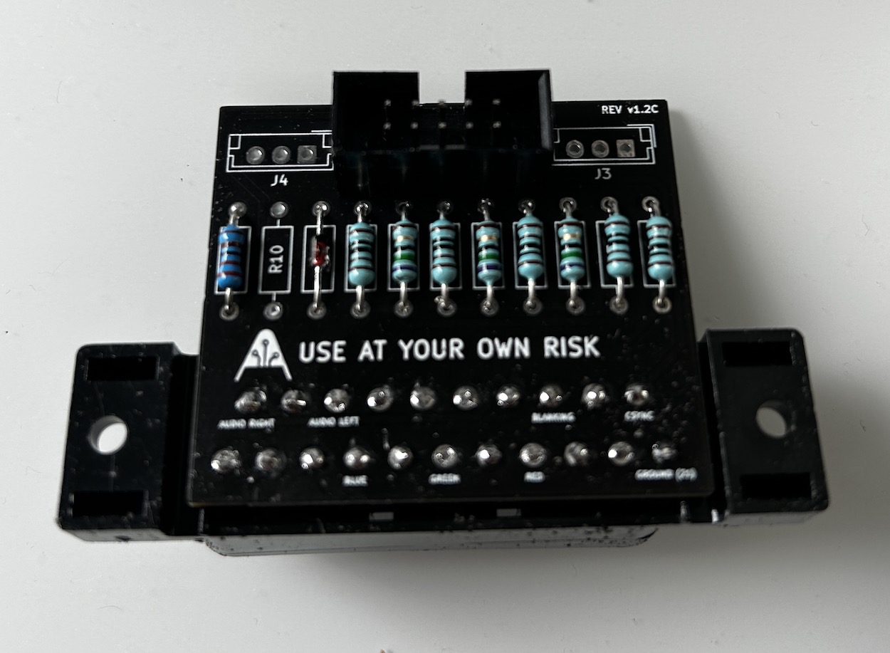
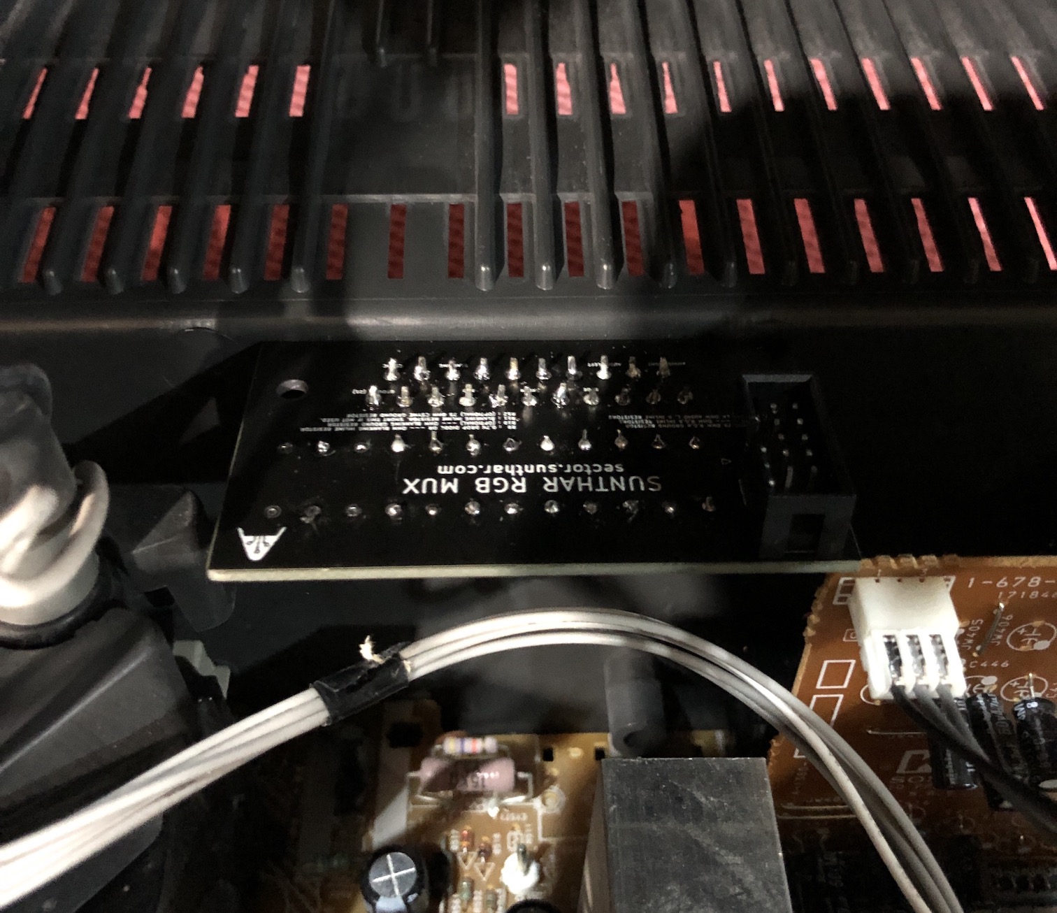
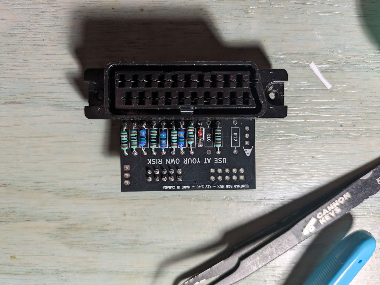
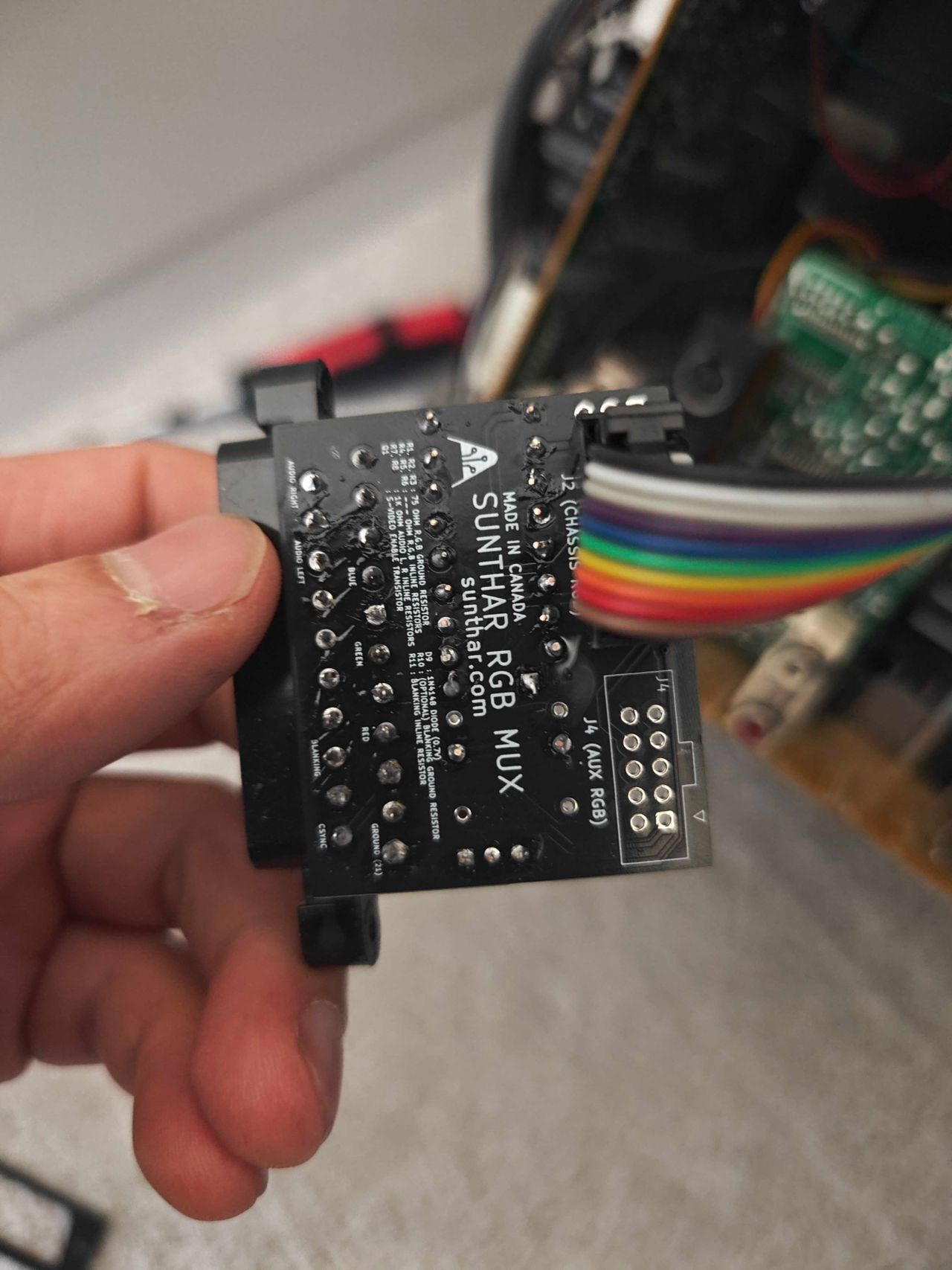
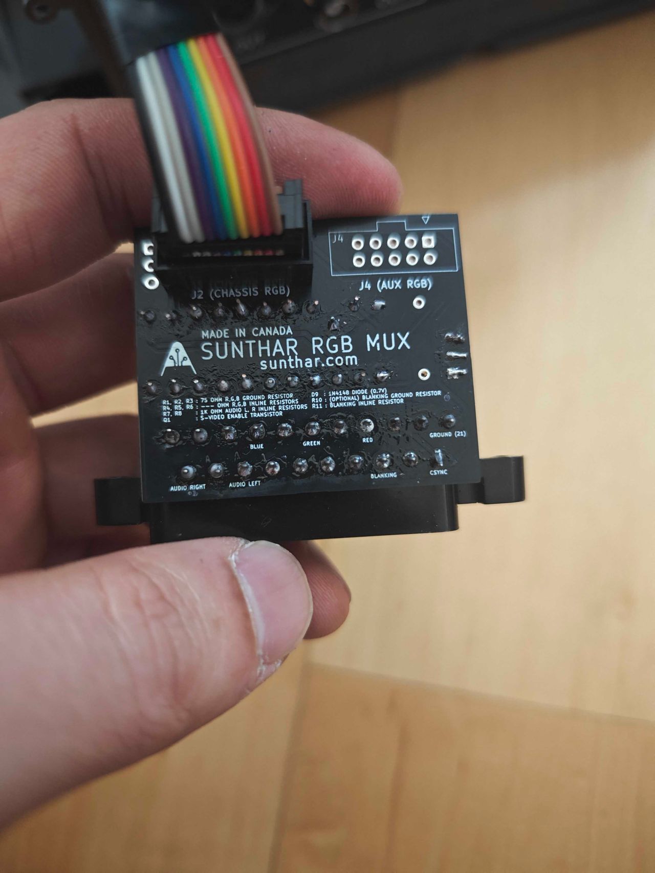
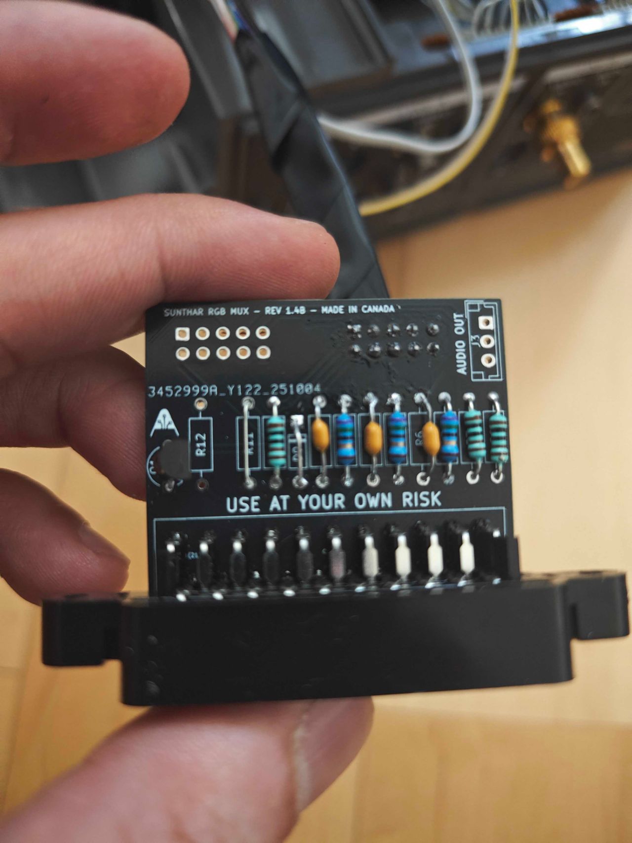
STEP 3: Build your mux board
This mod uses the RGB mux board. This is optional, but will make your mod easier and stable. You can also create the circuit presented in the schematics above without the board. Please also checkout the mux calculator to play with your own values.
| On Sony CRT Chassis | KV-20FV12 |
|---|---|
| CRT RGB inline resistor | 6.8kΩ |
| CRT RGB ground resistors removed | 680Ω |
| 0.1μF caps replaced | No |
| Add diodes on chassis RGB lines? | Yes |
| Add blanking diode on chassis | No |
| RGB mux board | KV-20FV12 |
|---|---|
| Mux board RGB termination (R1, R2, R3) | 75Ω |
| Mux board RGB inline resistors (R4, R5, R6) | 1kΩ |
| Mux board Audio LR (R7, R8) | 1kΩ |
| Mux board blanking diode (R9) | 1N4148 |
| Mux board blanking ground resistor (R10) | open |
| Mux board blanking resistor (R11) | 1kΩ |
Compatible mux boards:
It is recommended to use the variant C mini board for this CRT with the straight SCART connector. Variant B board can be used, if the spacing is carefully planned.
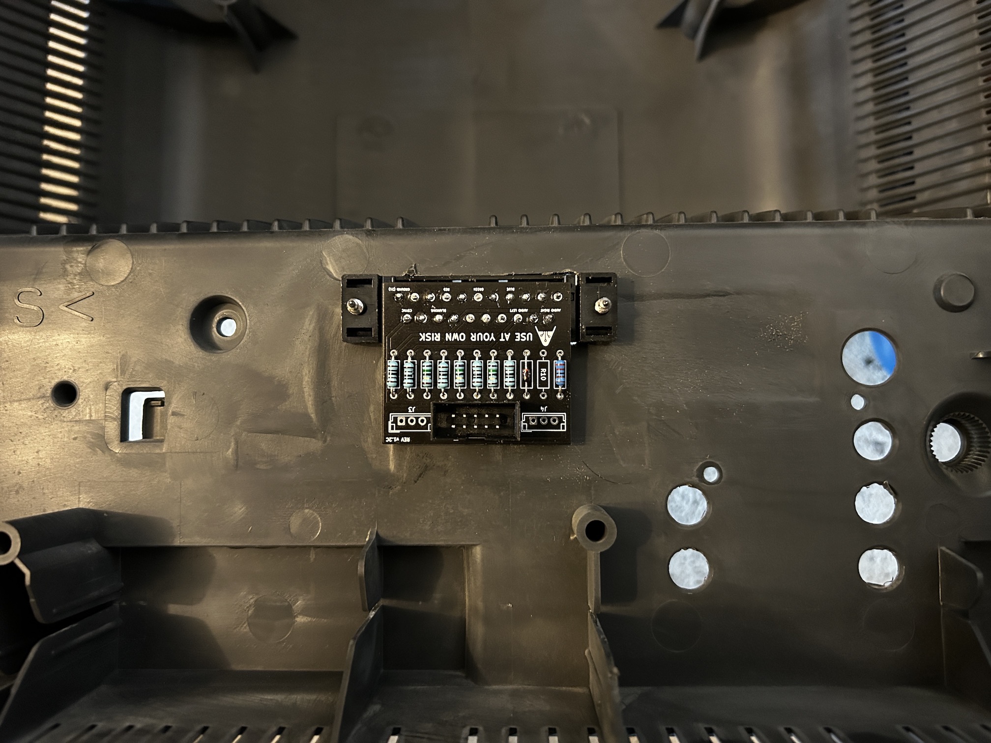
STEP 4: Attach the female SCART connector to TV
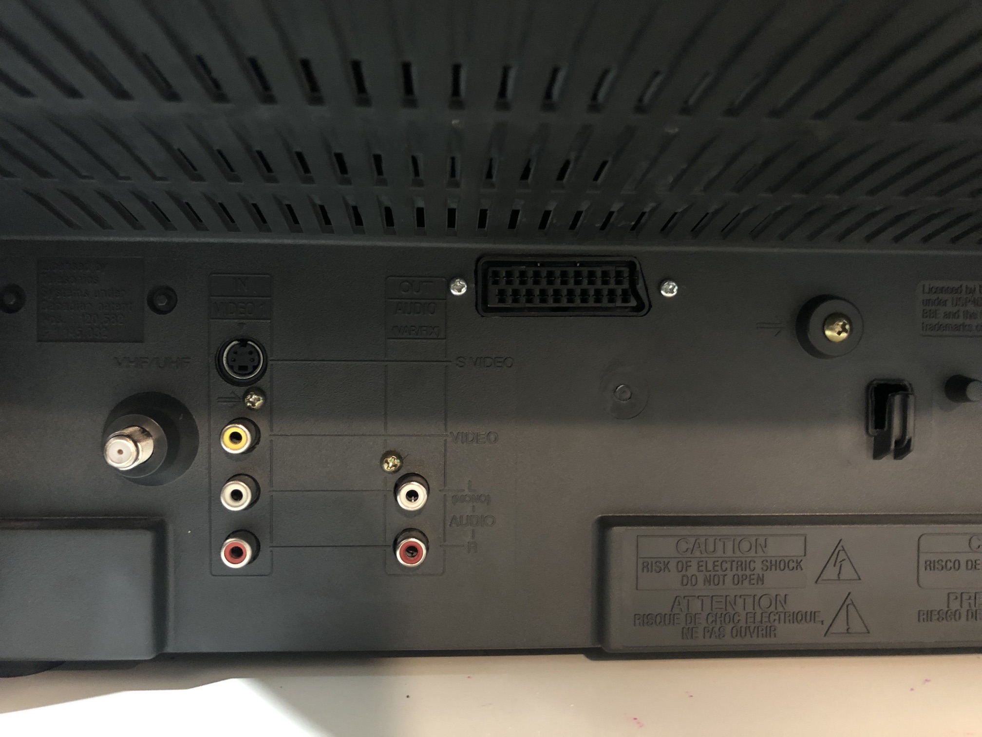
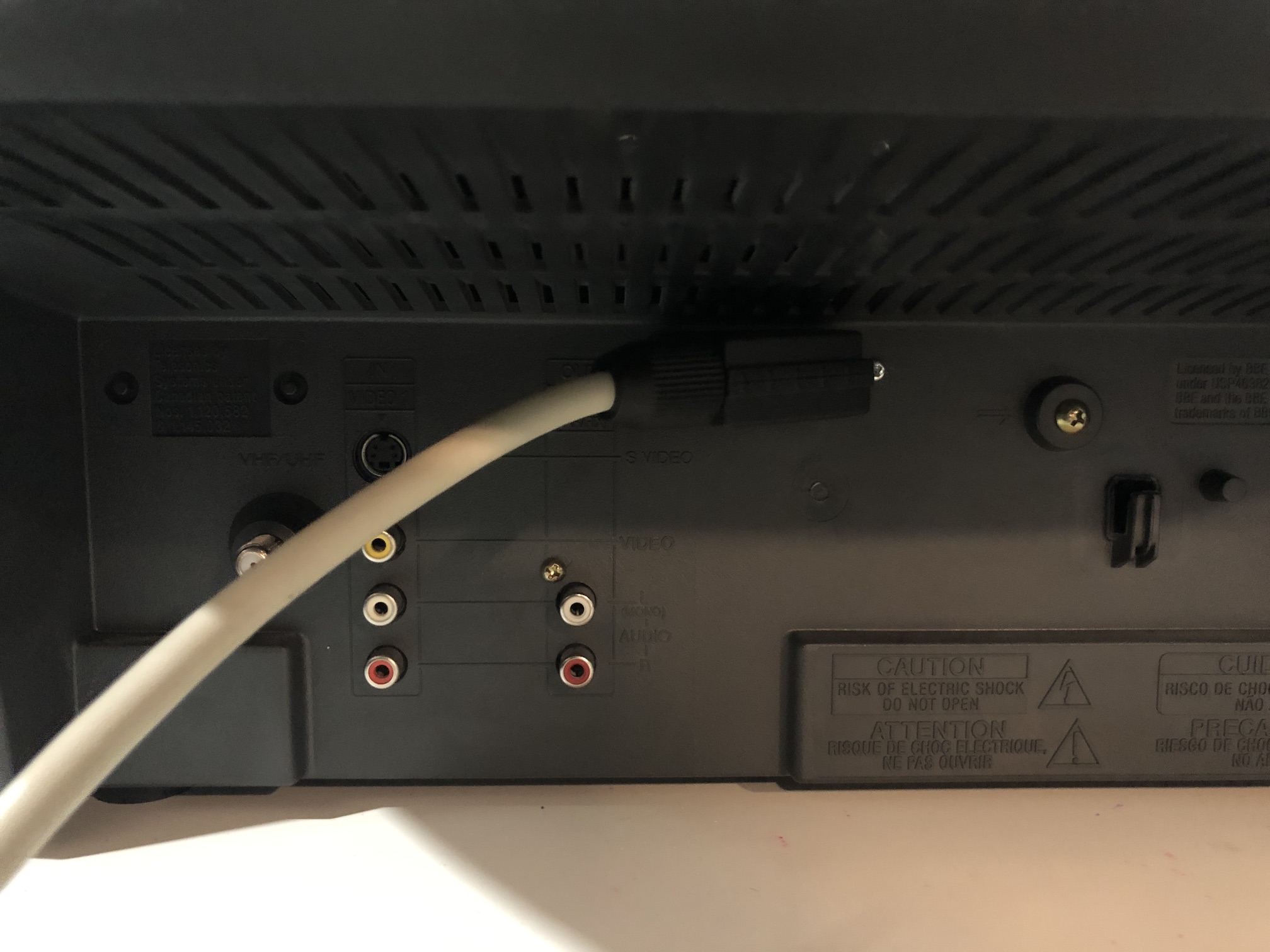
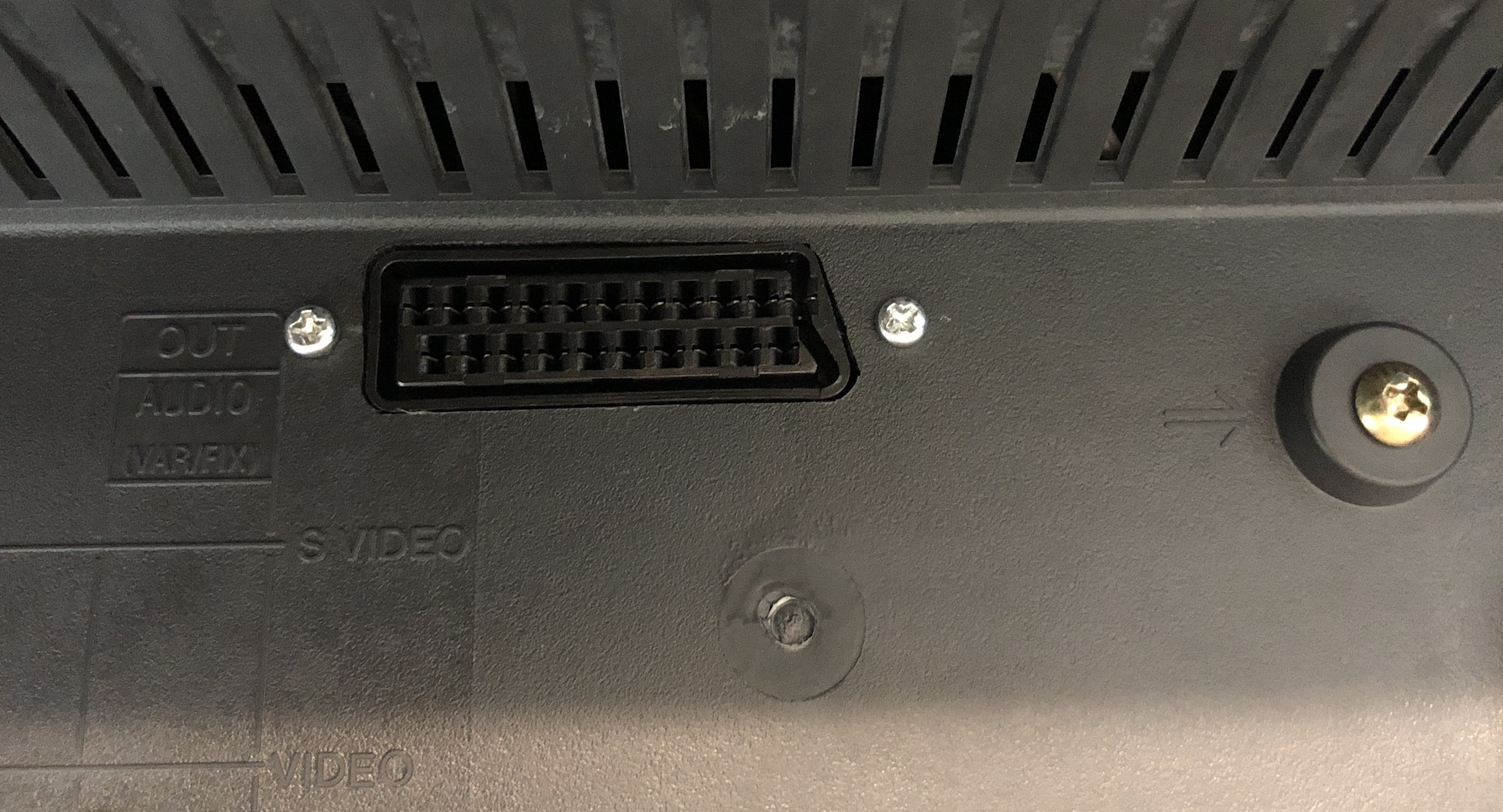
Creating a SCART cutout and mounting it is an art. I have a dedicated section for it.
How to create and mount a SCART female plug?
Getting into the service menu
- Turn the set on and then put into standby
- Press the
Display,5,VOL +buttons in sequence - Turn on the CRT and you should be in service mode
- Use buttons "1" and "4" on the remote control to navigate the service menu
- Use buttons "3" and "6" to adjust the selected data
Pictures of the mod
Mux and OSD
Volume 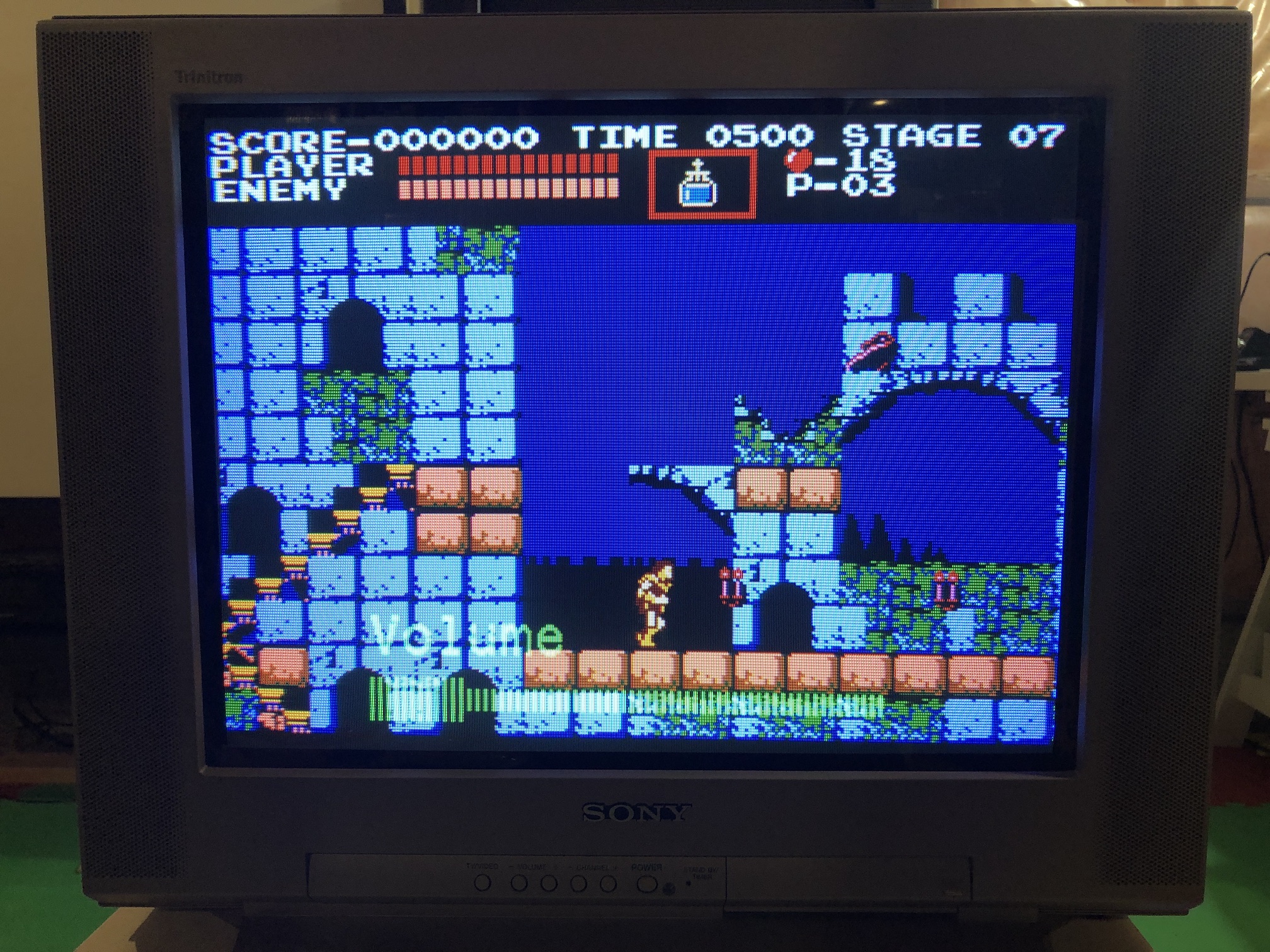
Menu 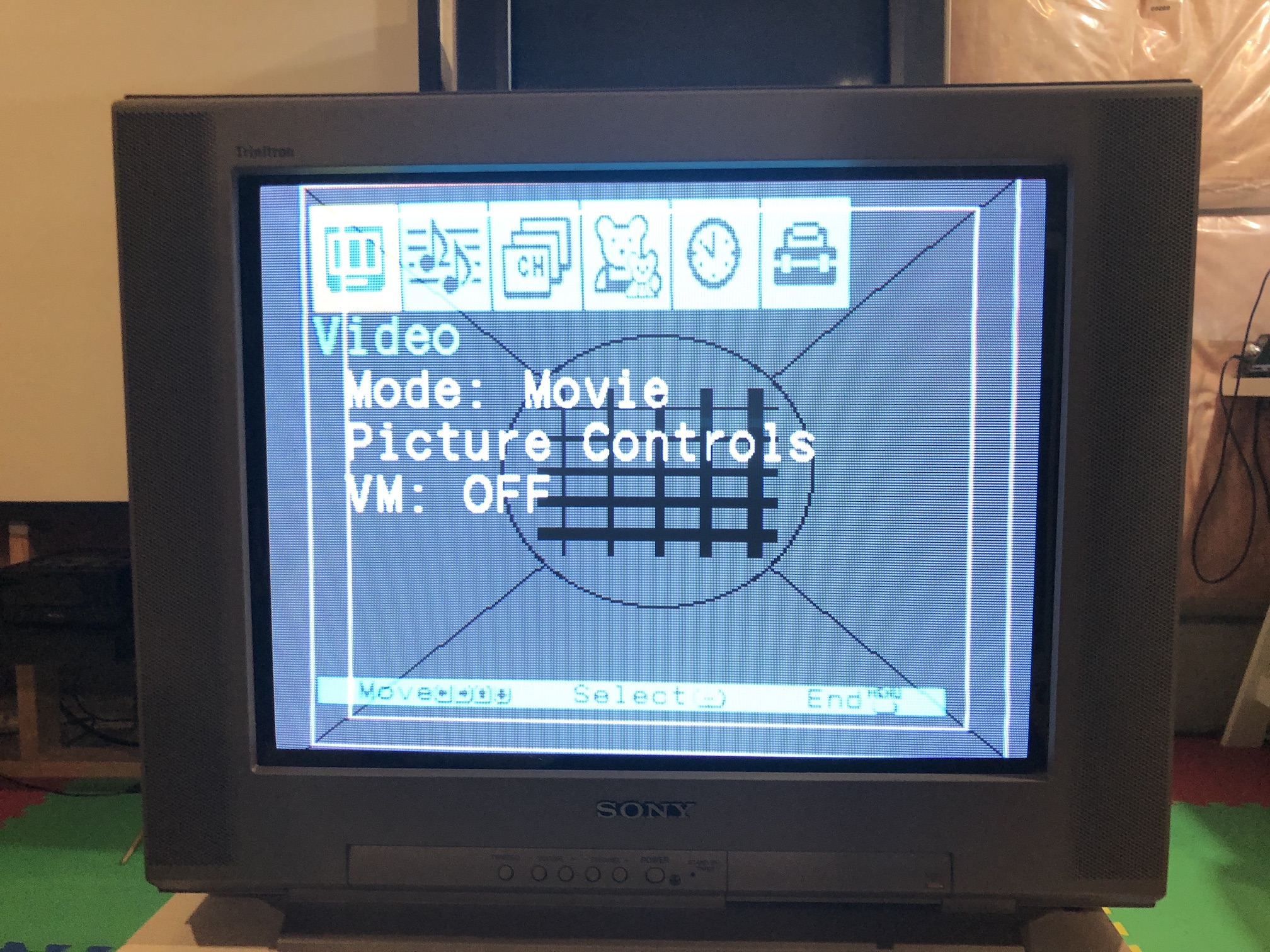
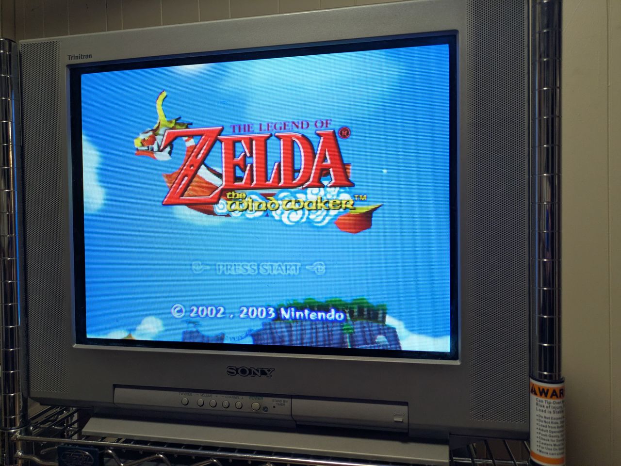
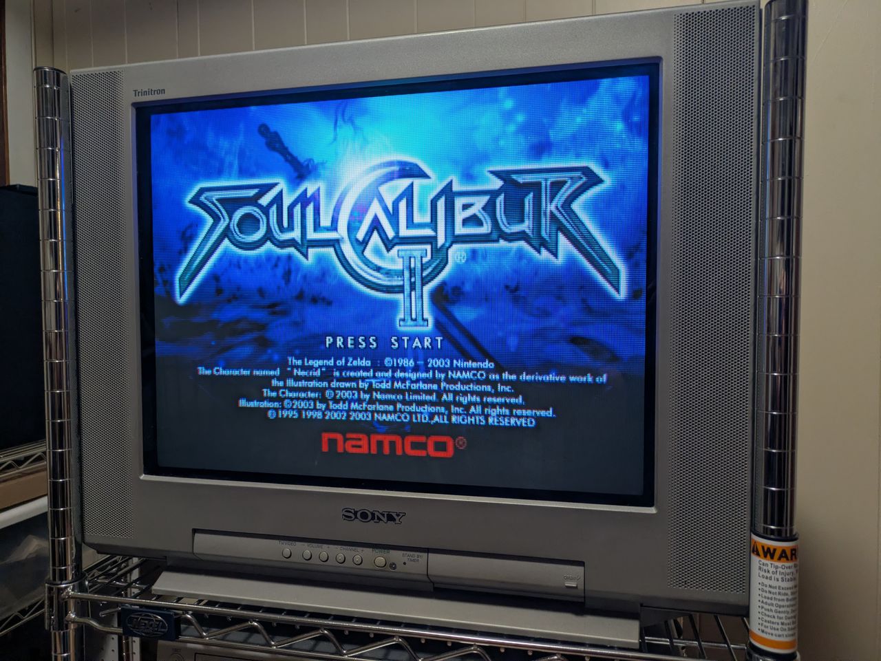
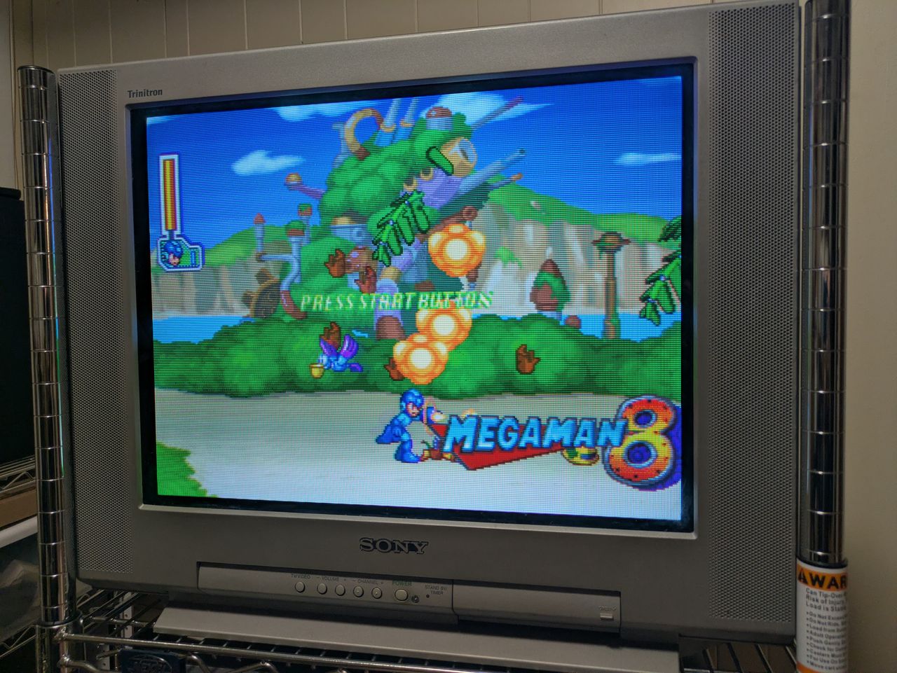
Games
NES - Adventure Island 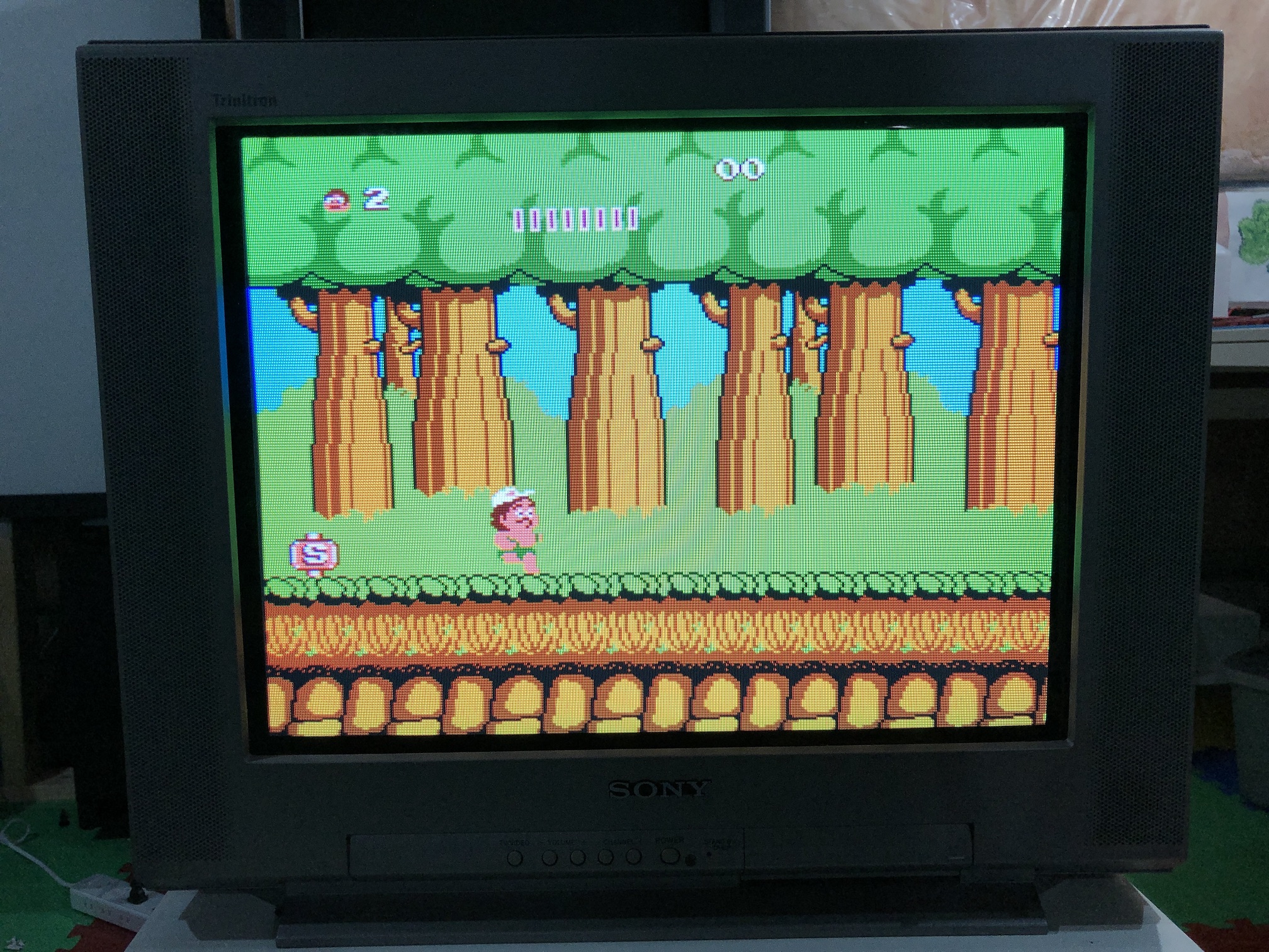
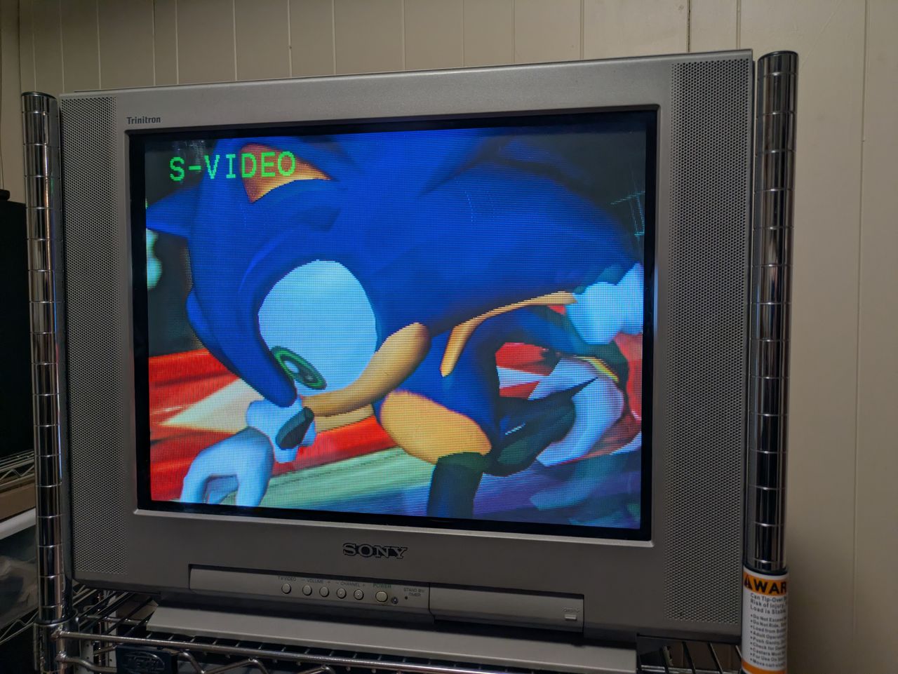
SEGA Genesis - Sonic 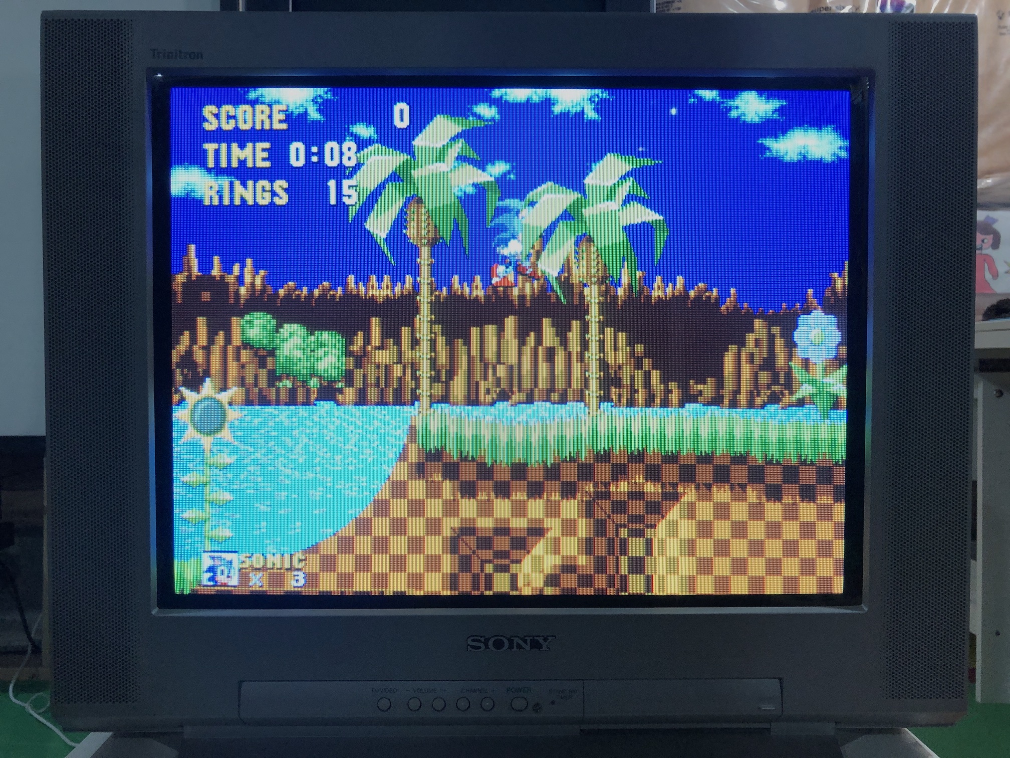
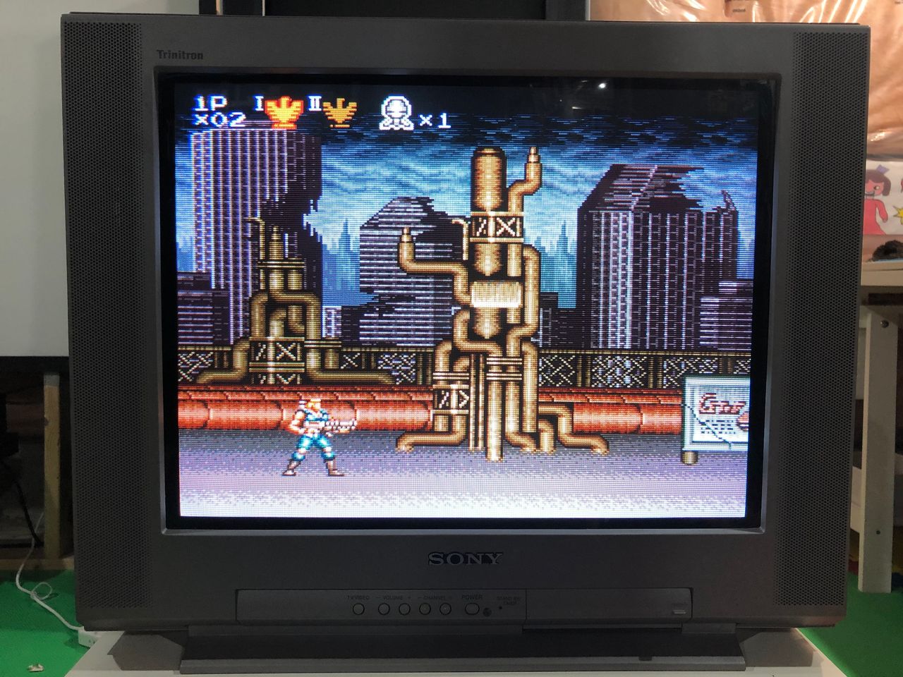
SNES - Contra 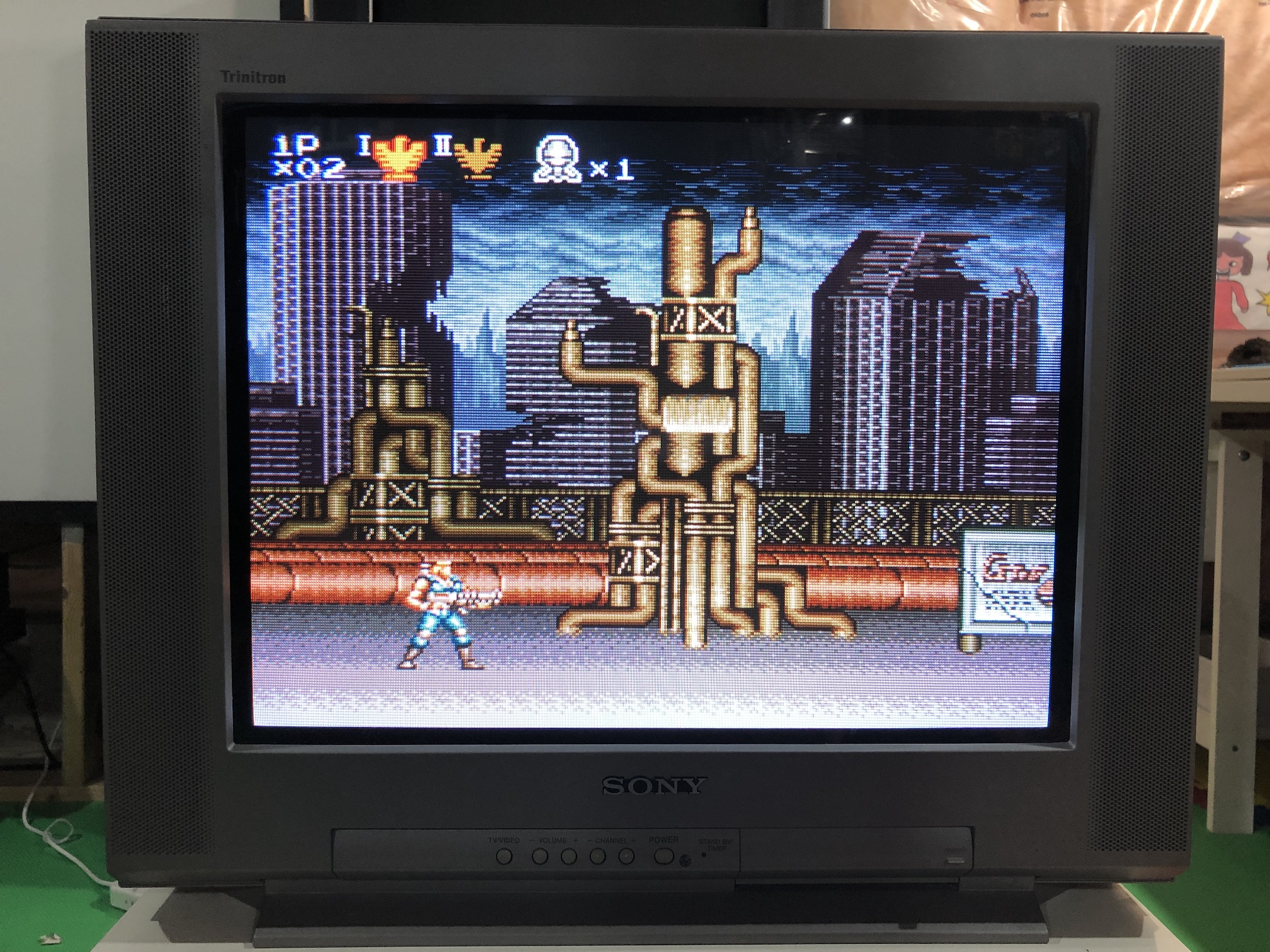
SNES - Alien 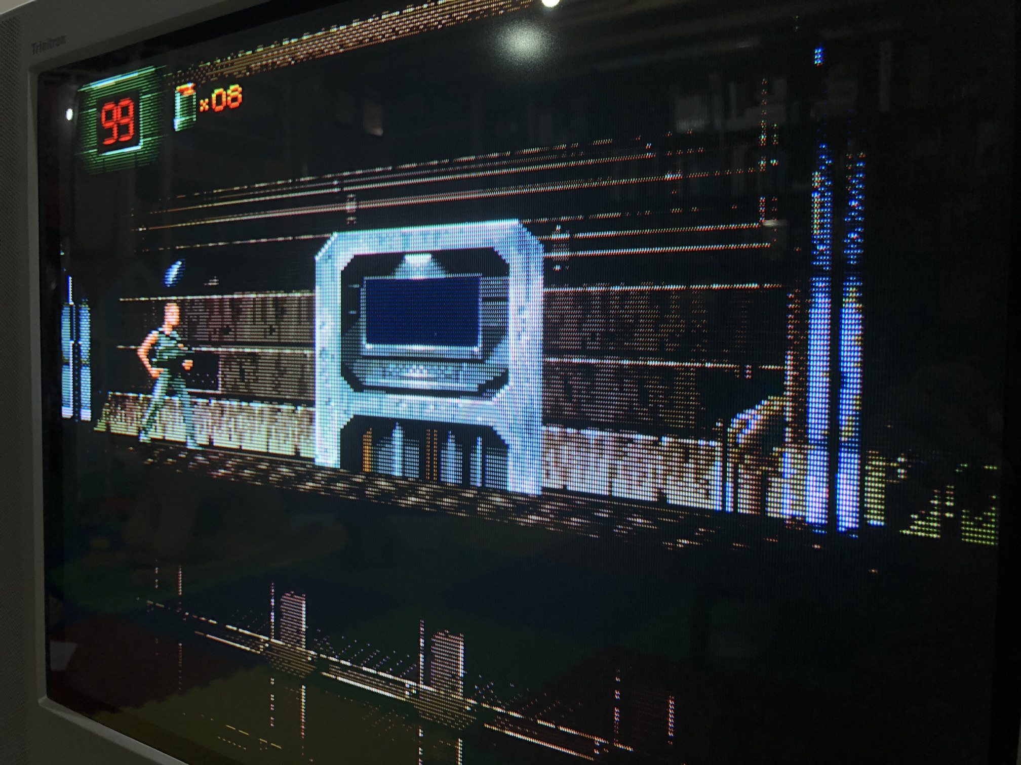
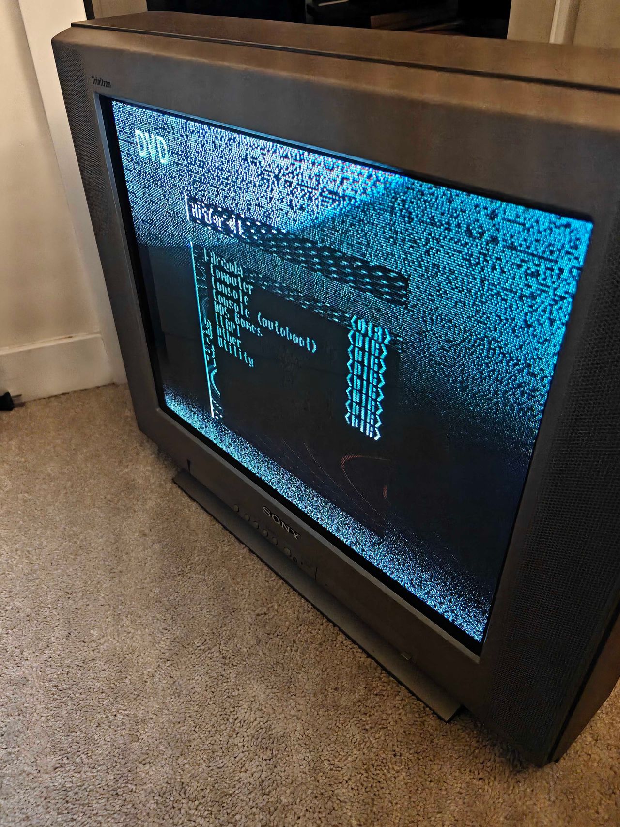
XBOX - UnleashX 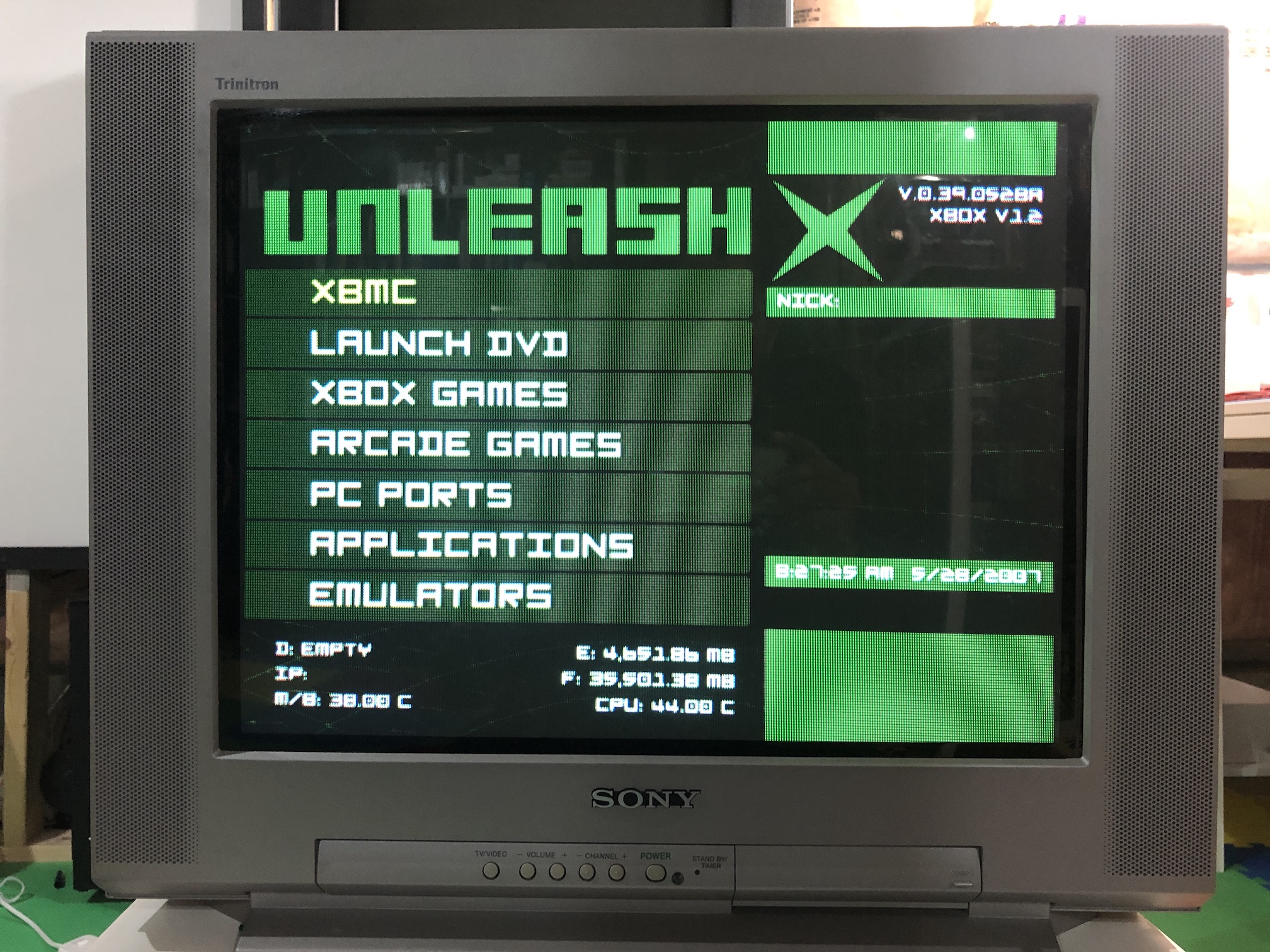
PS1 - Boot 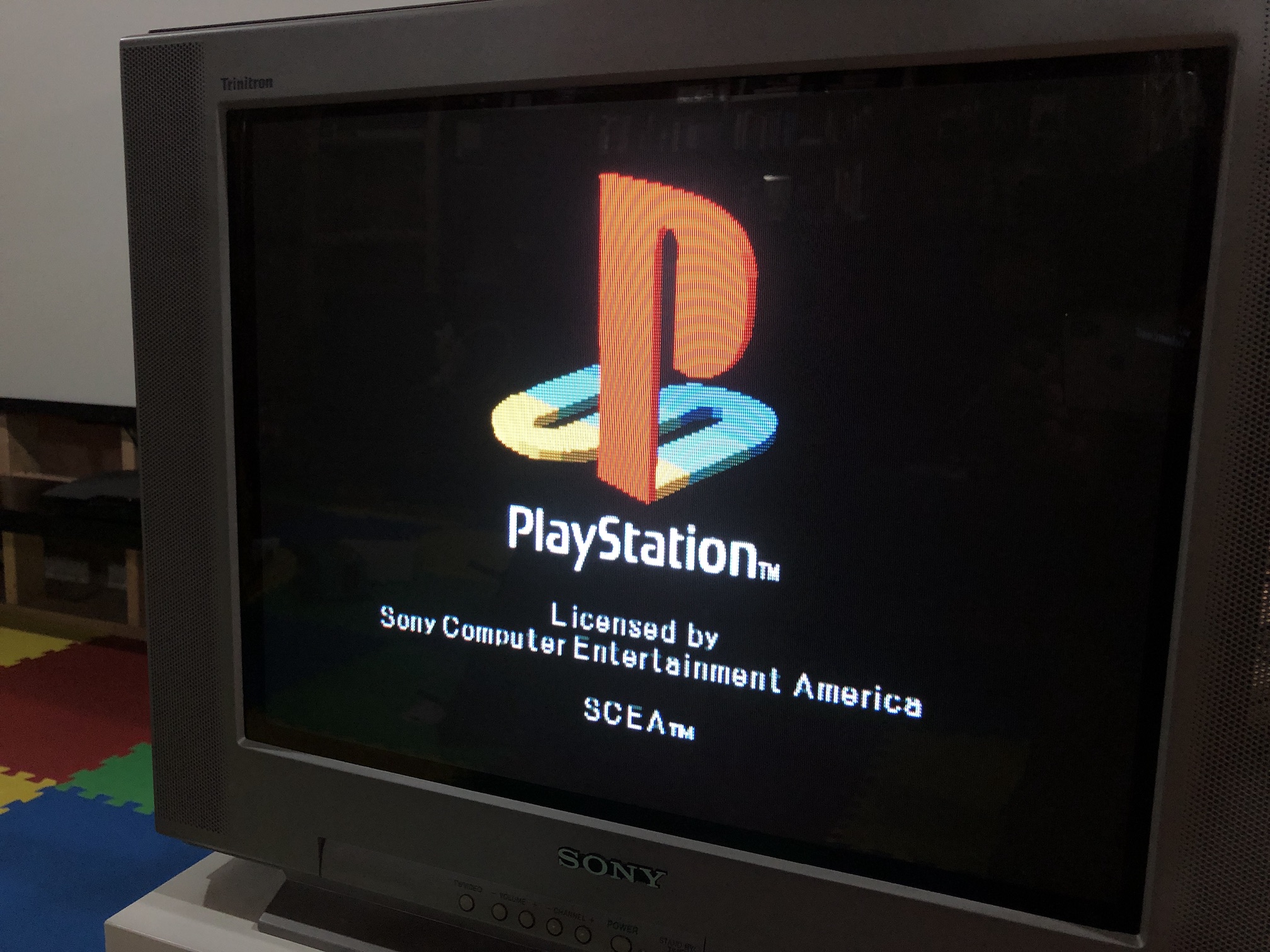
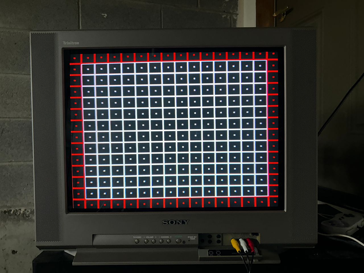
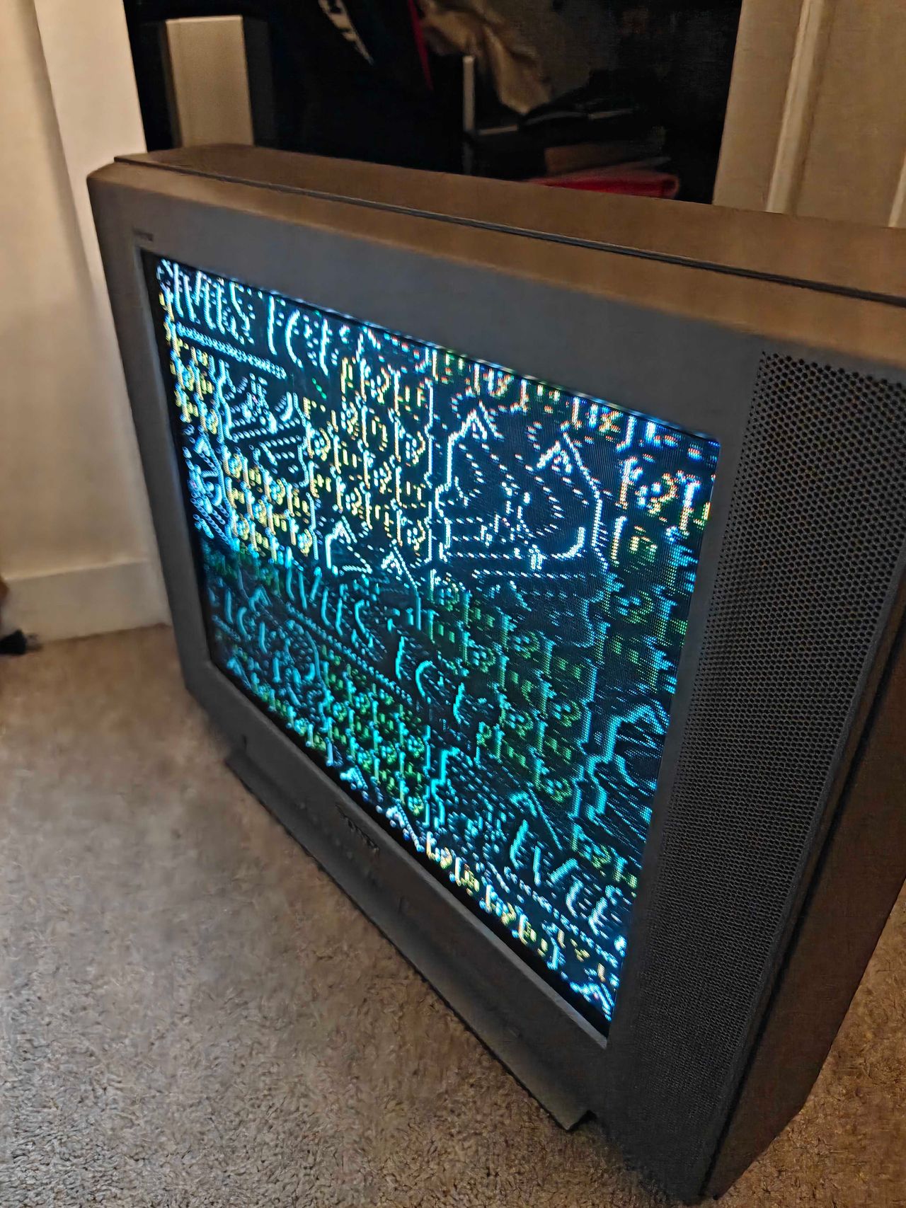
Patterns
SMPTE - Colors 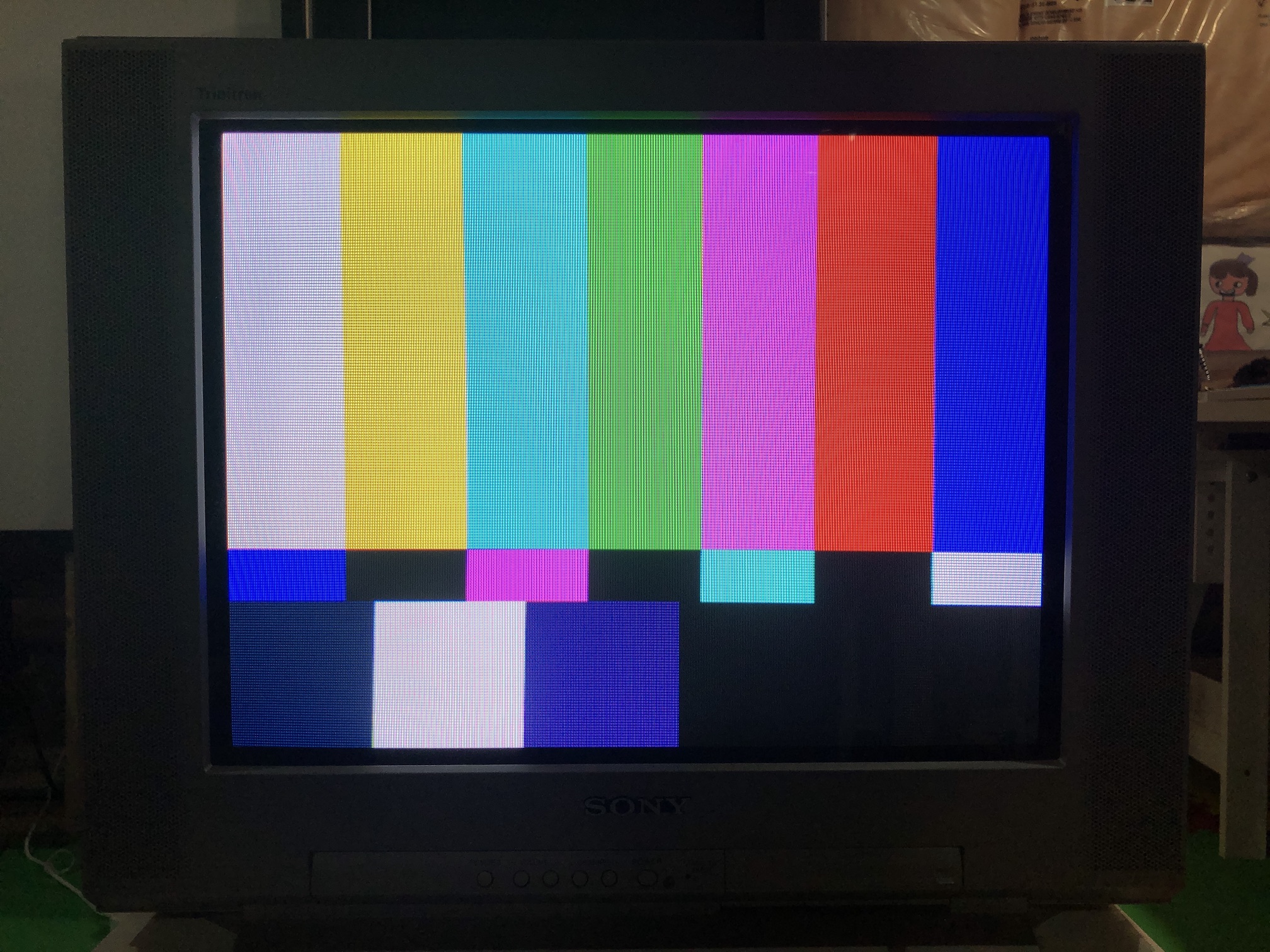
Grid 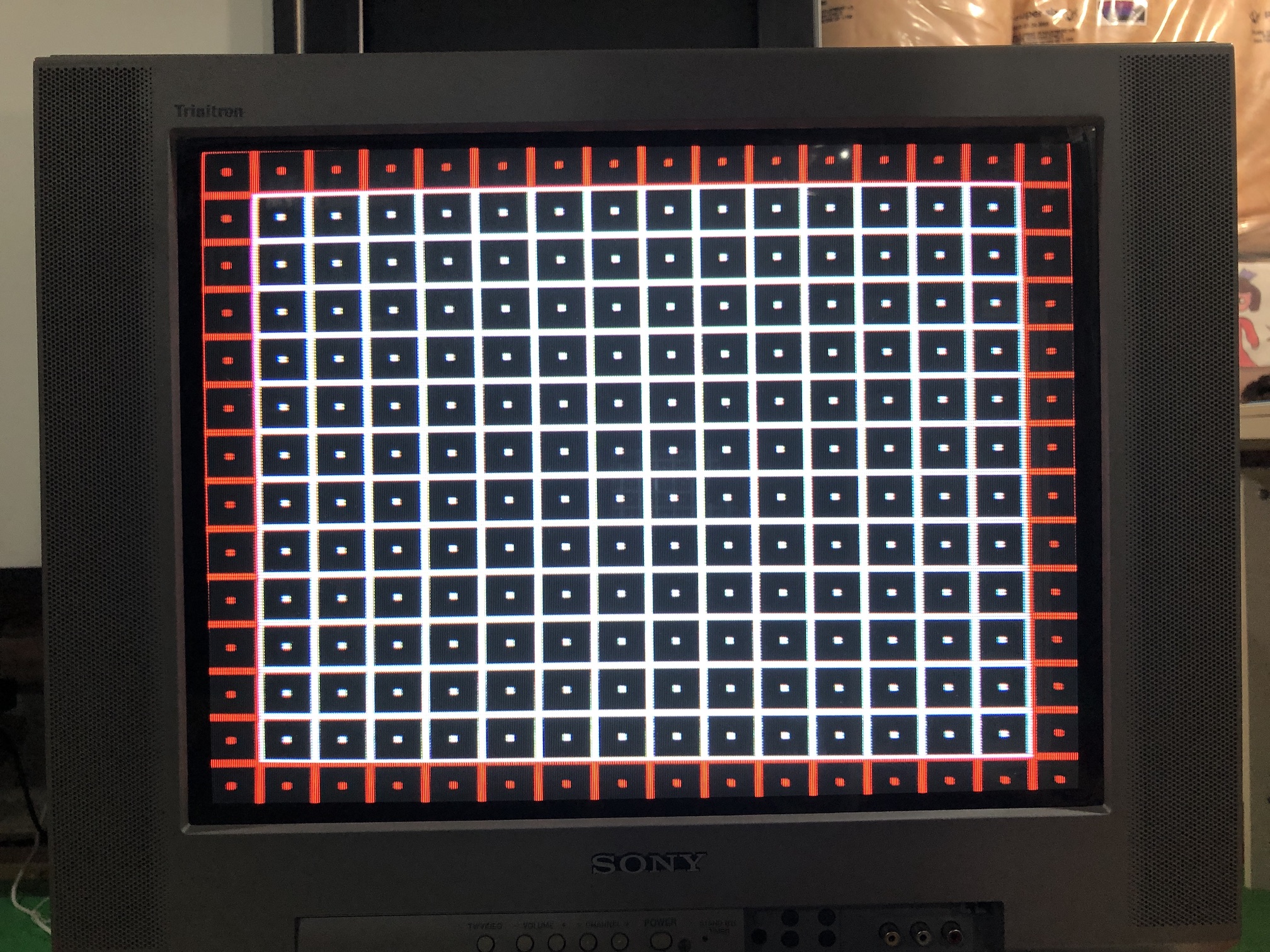
Monoscope 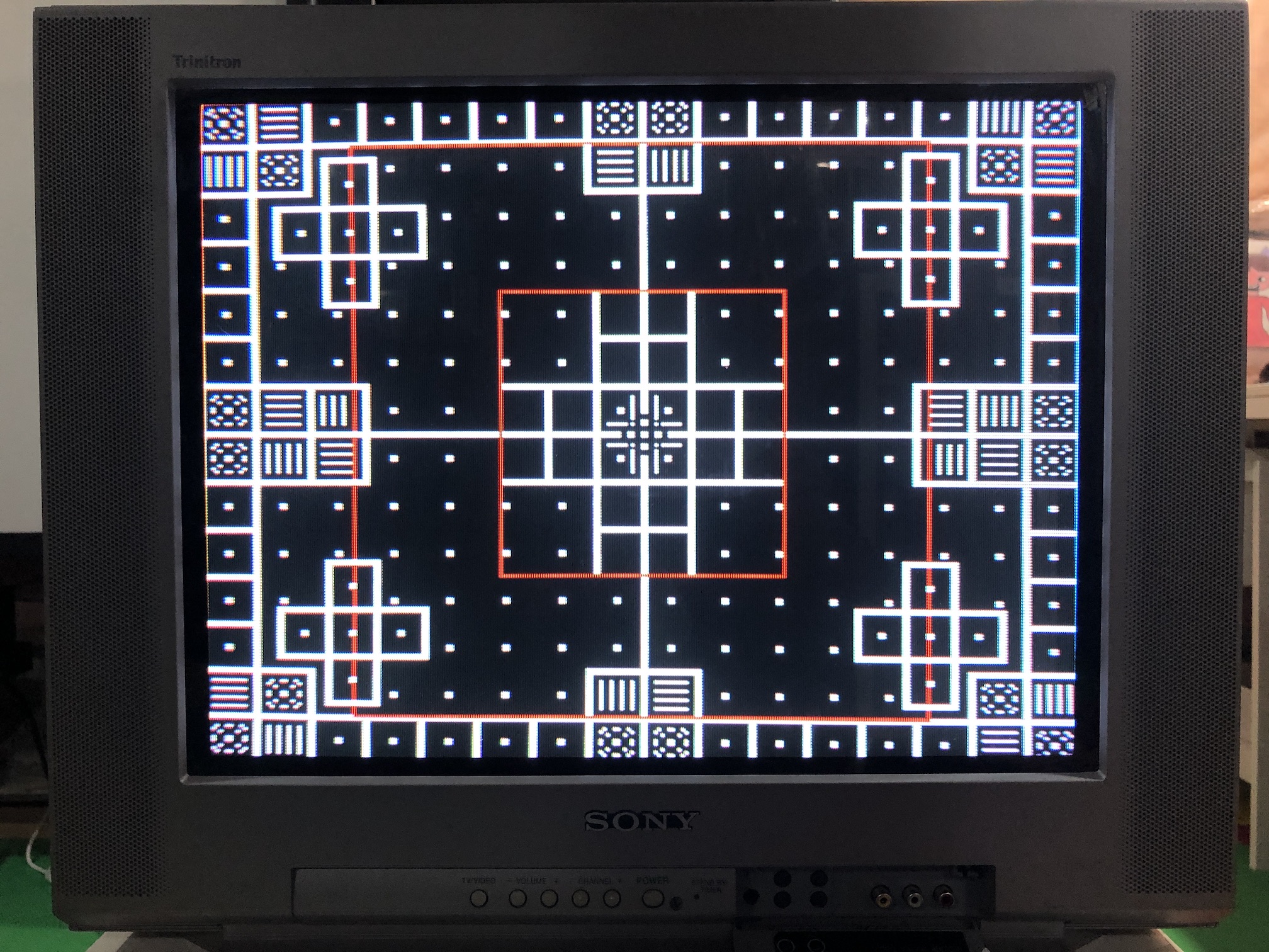
Inside of the CRT
Gut of the CRT (comes off completely). Main chassis, MB board, Neck board 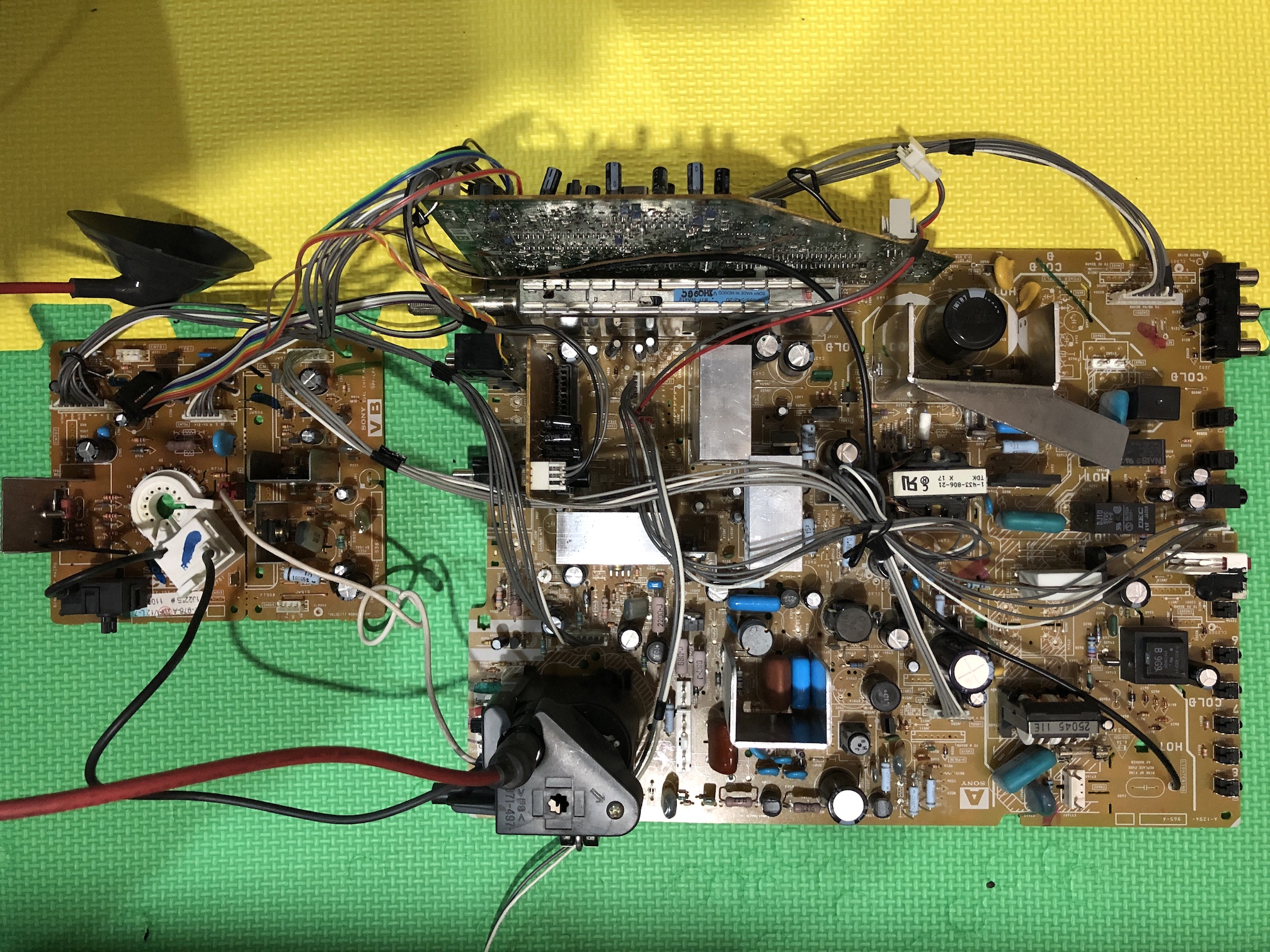
Tube and speakers 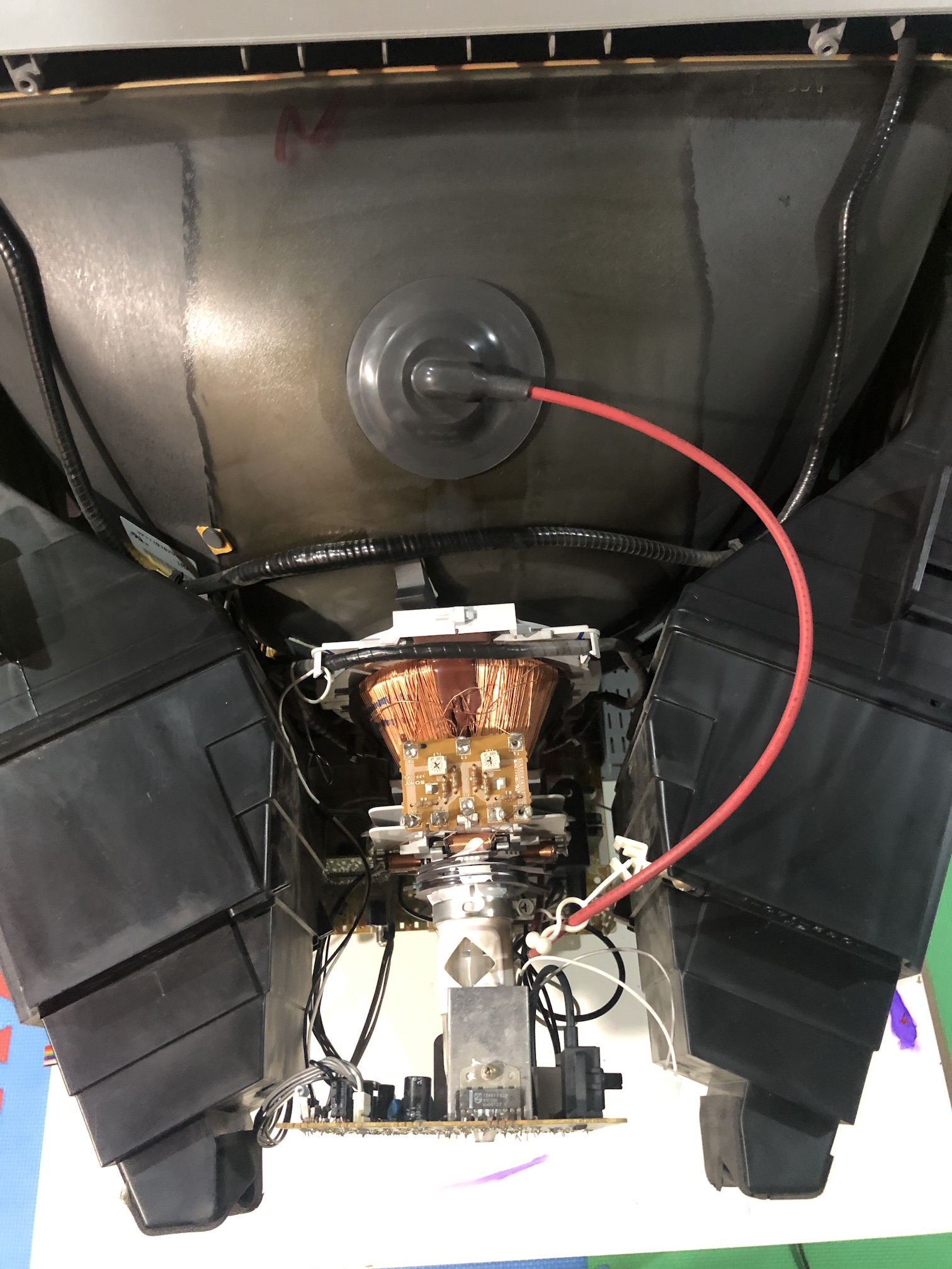
Neck board 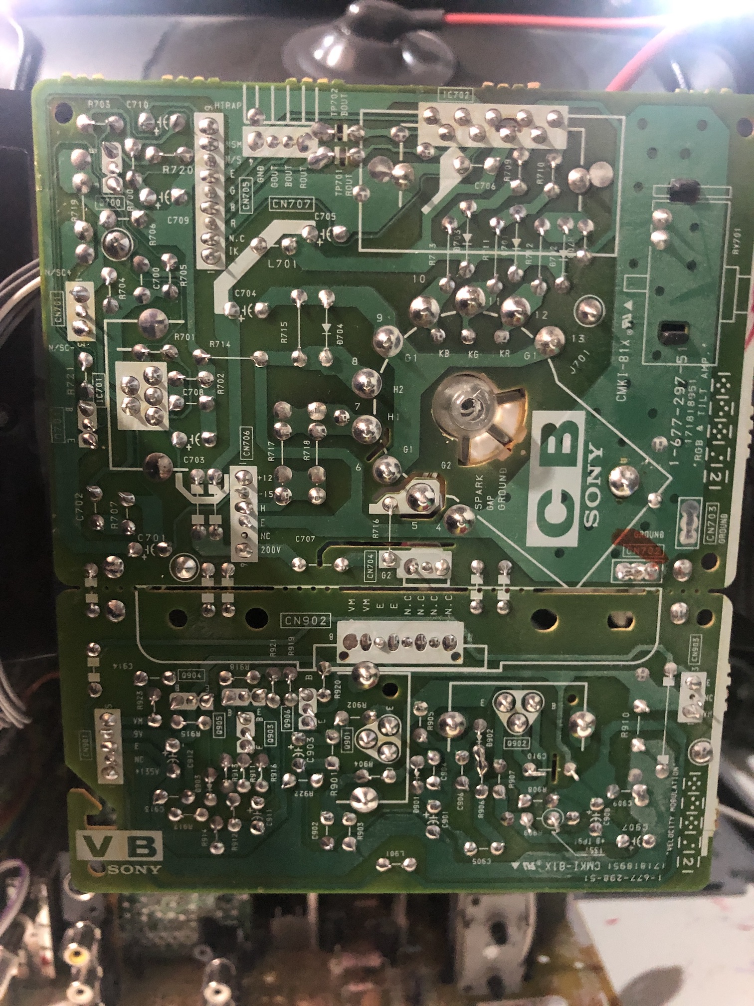
Pictures
Photos by Dan Lavoie
RGB modification showcase converted from a community support request.

Photos by Wei Lin
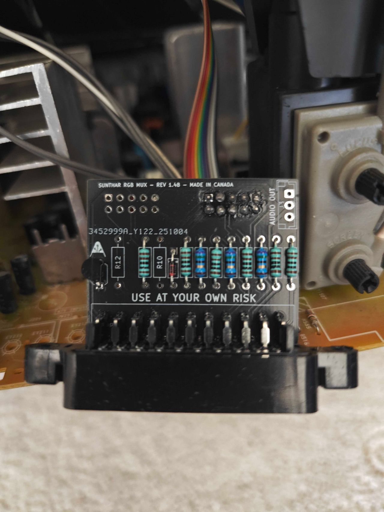
In this RGB modification project, a Sony KV-20FV12 CRT television was enhanced using a Rev 1.4B mini RGB mux kit.
Reference Photos