Sony (BA-2) KV-20S10
Sony (BA-2) KV-20S10 CRT RGB mod
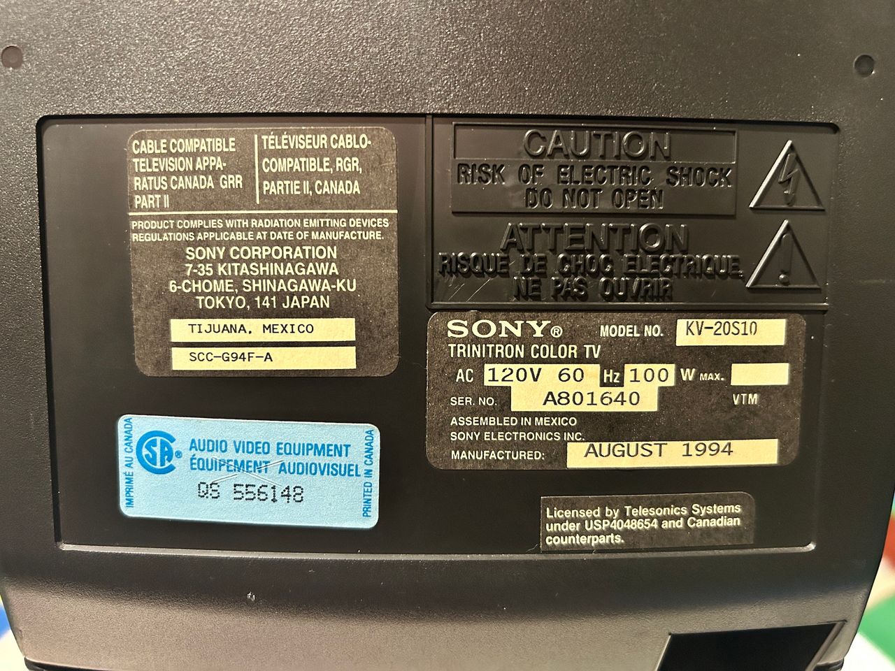
The Sony Trinitron KV-20S10 is a 20" curved CRT television released in 1994, featuring the BA-2 chassis. Renowned for its classic, boxy 90s aesthetic, this model is highly sought after due to its compact size, RGB moddability, sharp picture quality, and excellent 2D scrolling geometry.
View full CRT details and more mod examples →
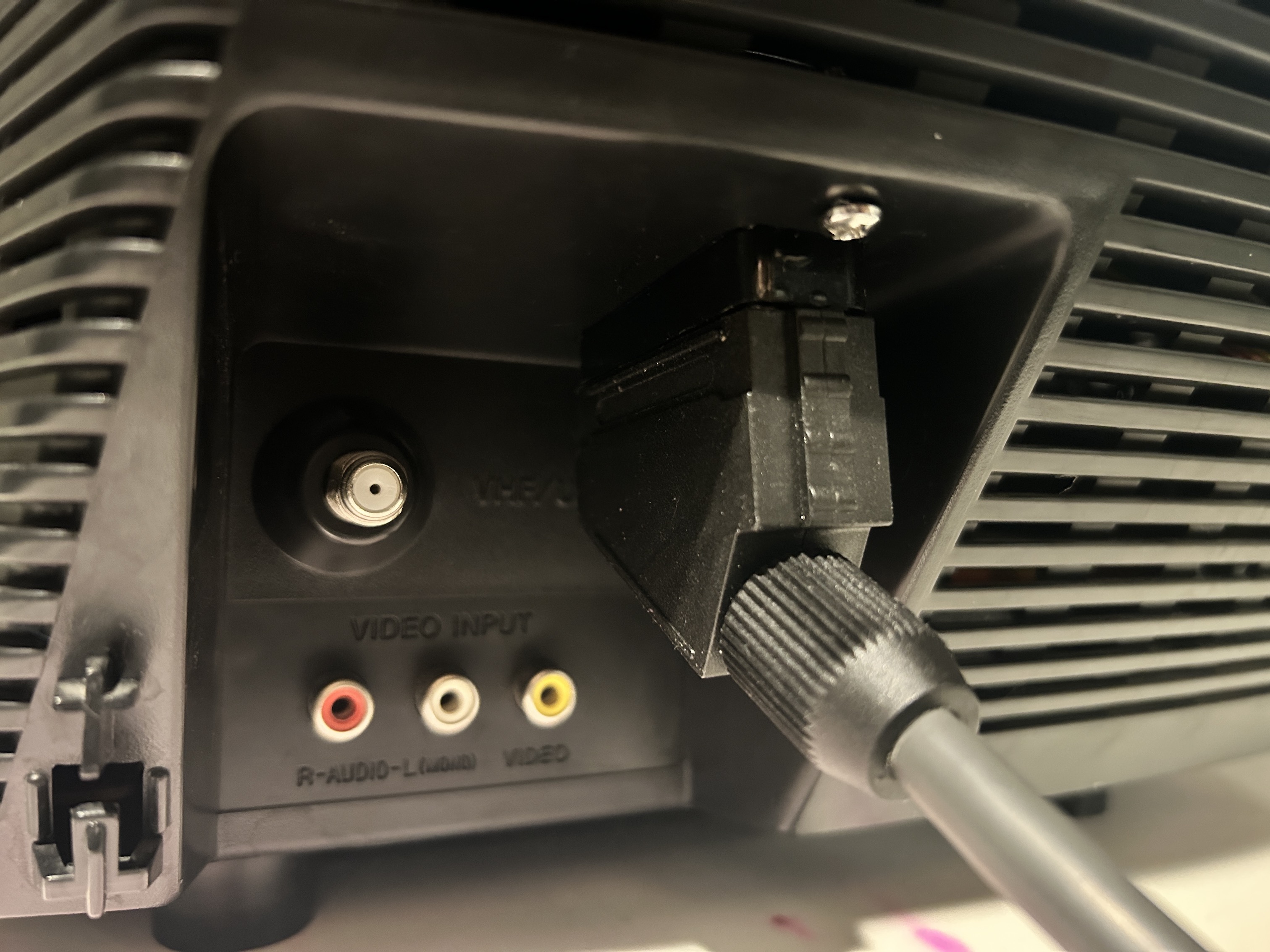
This Trinitron model used a single chassis design and featured built-in stereo speakers, along with one composite video input and an RF input on the rear panel. It also included a single headphone jack on the front. Performing an RGB modification on this set was both worthwhile and relatively straightforward, as it already contained an unused analog RGB input that could be easily repurposed.
The RGB image exhibited a slight underscan that was not present when using the composite input. Although most of the capacitors tested within specification, some showed minor ESR drift. I reflowed the entire chassis and replaced several electrolytic capacitors, but neither of these measures resolved the RGB underscan issue. They did, however, noticeably improve the overall image quality.
This experience reinforced an important lesson: a blind recap is not always the solution. Proper diagnosis requires the use of an oscilloscope and careful signal measurements to identify the root cause. In addition to electrolytic capacitors, other components can drift out of specification over time, including film capacitors and resistors.
Contributors
Thank you to everyone who contributed to this guide:
- Eli Krause — contributor, CRT specs from CRT Database.
- Sunthar — contributor, RGB mod and pictures
CRT safety
Caution
You can die doing this! So read carefully! CRT TV is not a toy. Do not open a CRT TV. If you don't have any prior knowledge about handling high voltage devices, this guide is not for you. CRT TV contains high enough voltage (20,000+ V) and current to be deadly, even when it is turned off.
Plan of attack
Manuals and Datasheets
Specs
- Manufactured: Mexico (1994)
- Format: NTSC
- Chassis: BA-2
- Tube: Sony Trinitron A51LDG50X
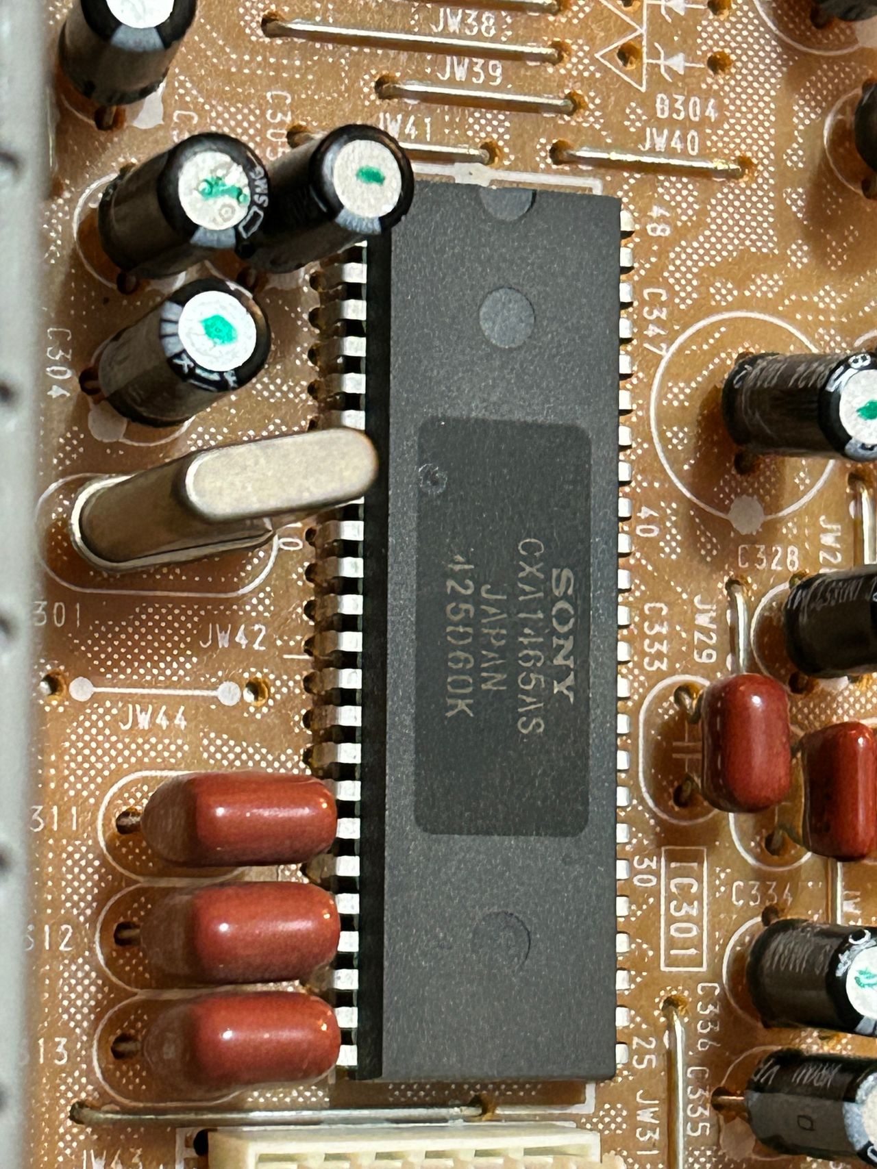
- Jungle Chip: Sony CXA1465AS
- OSD Chip: M37265M4
- Screen Size: 20"
- Weight: 48 lbs
- Inputs: Composite, RF
Schematics
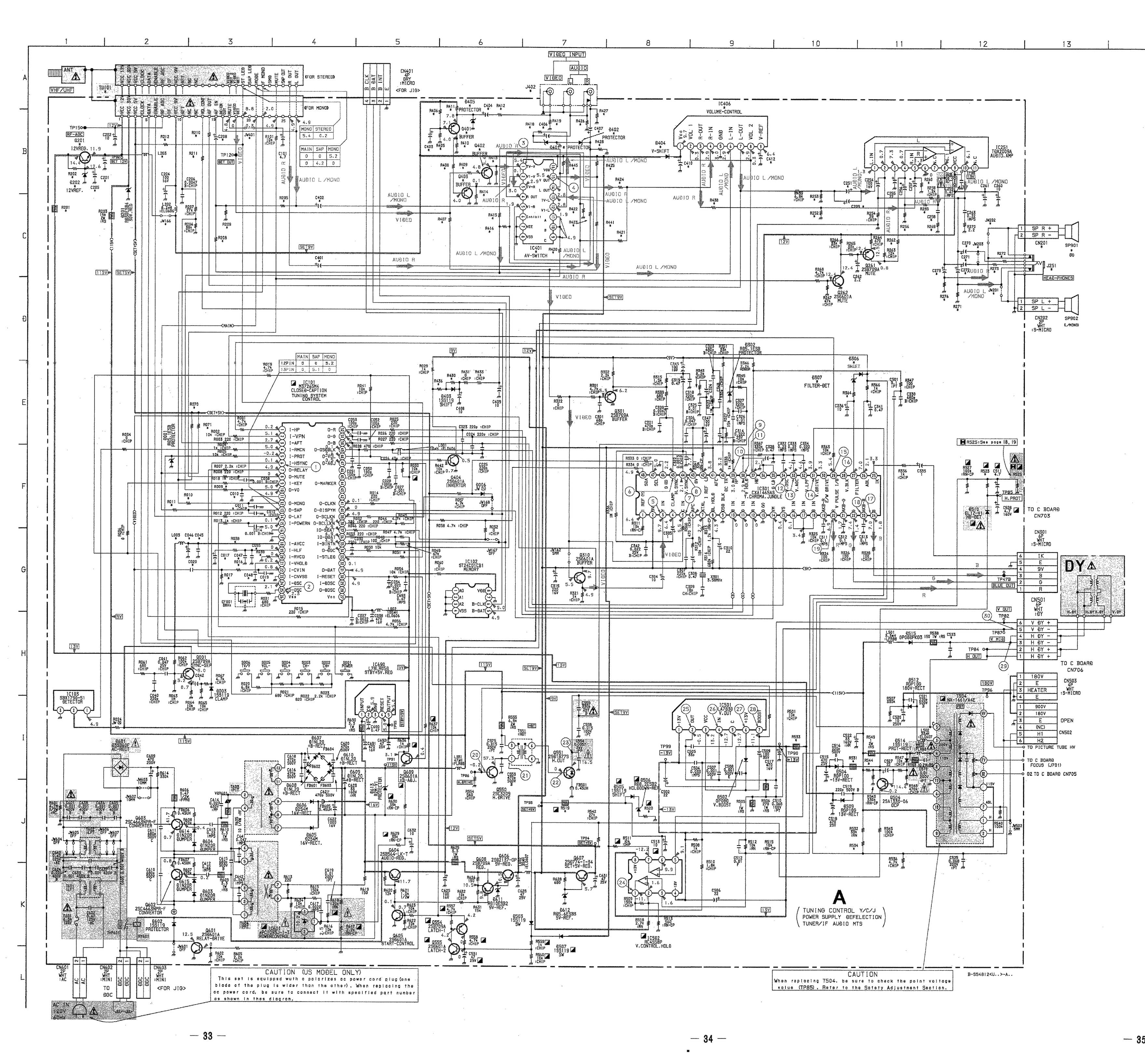
RGB mux diagram
Prepare the mux diagram. If you are building your own circuit, this diagram should help.
Performing the mod
You can't ask for a more straightforward RGB mod.
Fortunately this chassis doesn't require any muxing. You can pass R, G, B through a 0.1uF, 75ohm terminated wire directly to the chroma IC301. Blanking (Ys) can be fed through a 1kΩ + 0.7V didoe to pin 15 of the chroma.
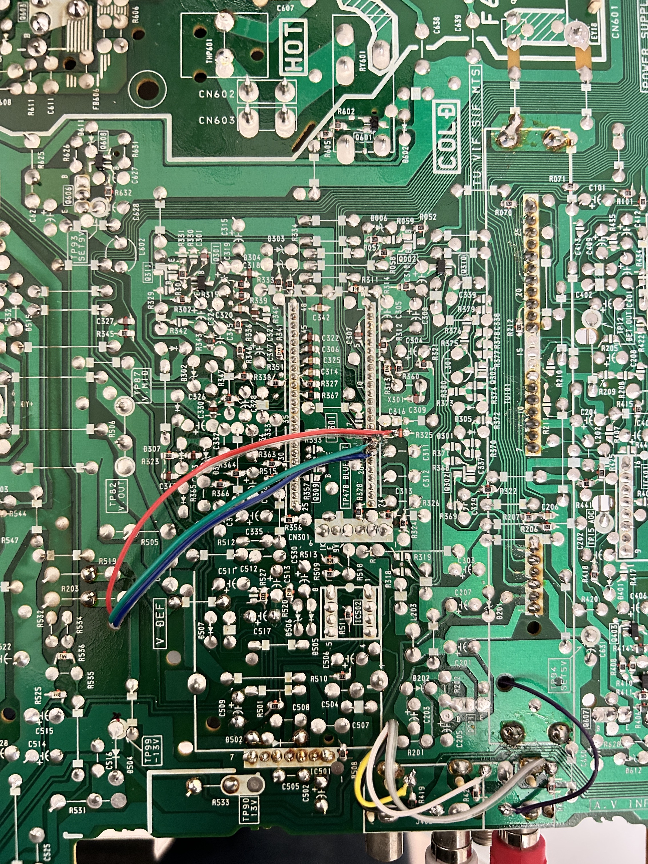
STEP 1: Free the RGB inputs
- Remove the R325 ground resistor (10kΩ) from the board.
- Carefully cut the traces on the board to ensure that the R, G, and B traces are no longer connected or shorted together.
- Make sure R, G and B are not connected to the ground either.
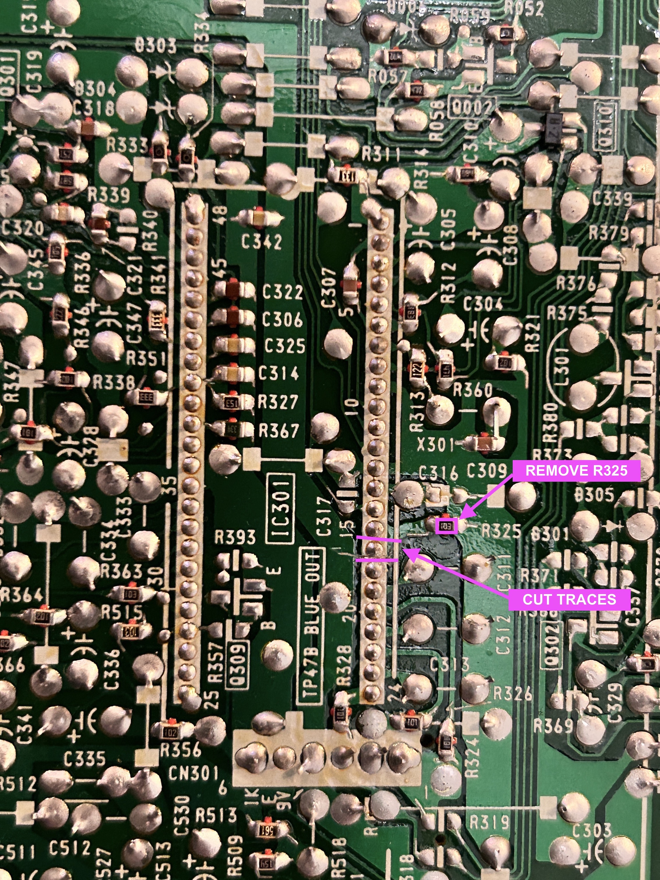
Cutting traces is the best approach and can be easily reversed back if needed.
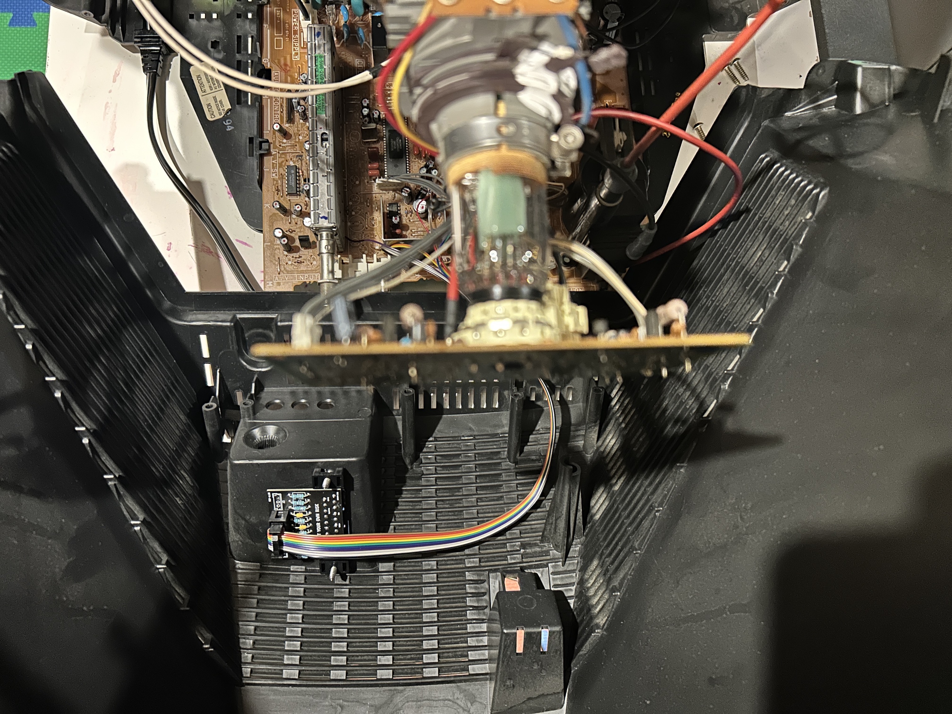
STEP 2: Connect RGB wires
See picture below to see where R, G, B wires should be connected. They are connected directly to the chroma IC. Red, Green, Blue lines are exposed on chroma pin 16, 17, 18 respectively. Since the gap here is really small, take care when soldering the wires.
STEP 3: Connect blanking
See picture below and reference the mux diagram above to connect the blanking. Inductor leg closer to the OSD was lifted and a diode was added (pay attention to where the stripe is pointing). Blanking was then injected in the middle.
![]()
STEP 4: Connect Sync, Audio and Ground
Sony KV-20S10 supports stereo. Therefore, audio left and audio right were wired as below. Suppose your BA-2 board only supports mono, you can twist both audio left and right and connect it to the mono audio input. 1 KkΩ audio resistors on the mux board will ensure right and left channels are mixed properly.
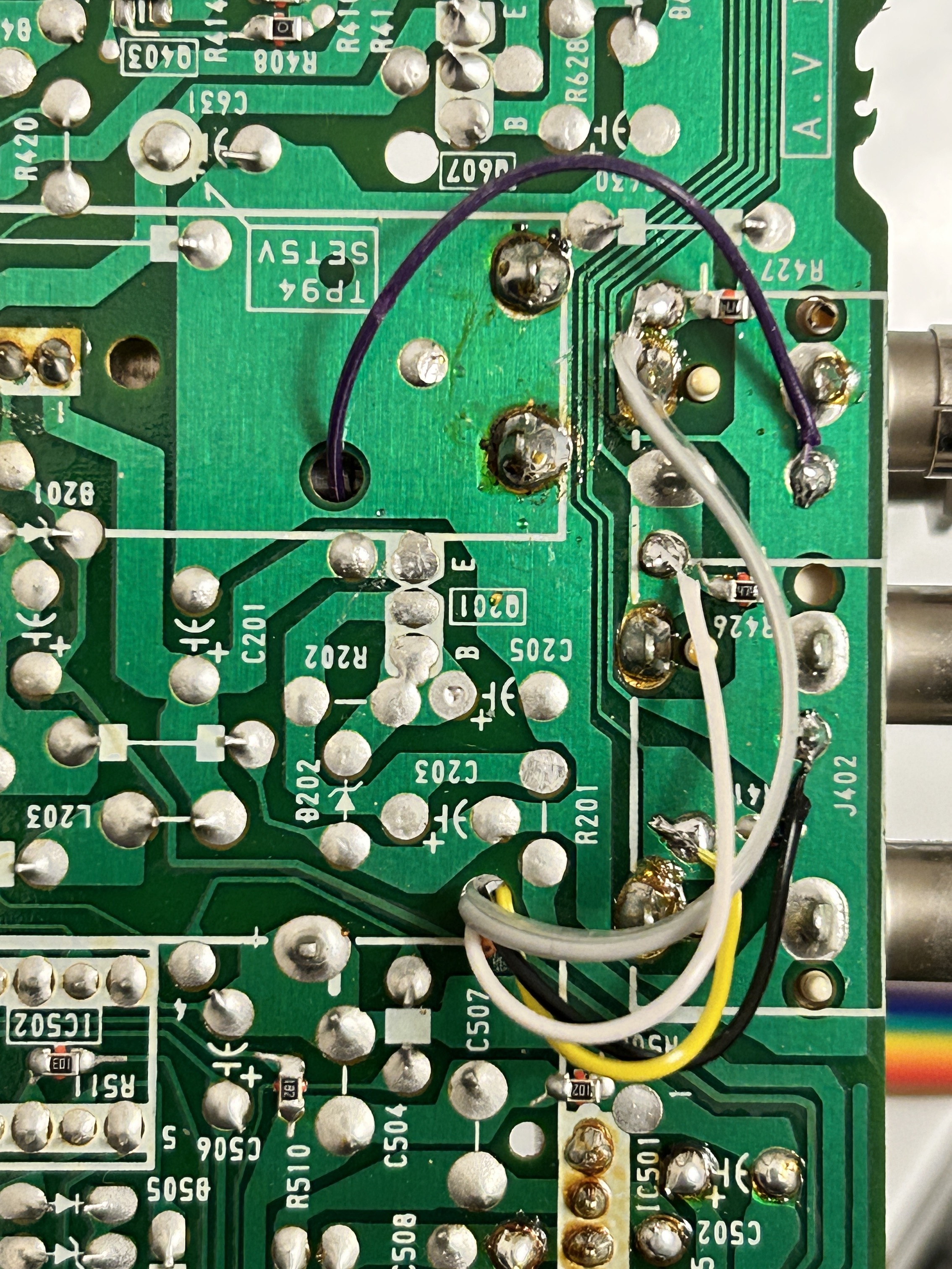
Sync wire (yellow) should be connected directly to the composite input.
Black wire is the common ground wire. With the latest 1.2B/1.2C PCB design you can leave both purple and orange wires floating or connect them to ground.
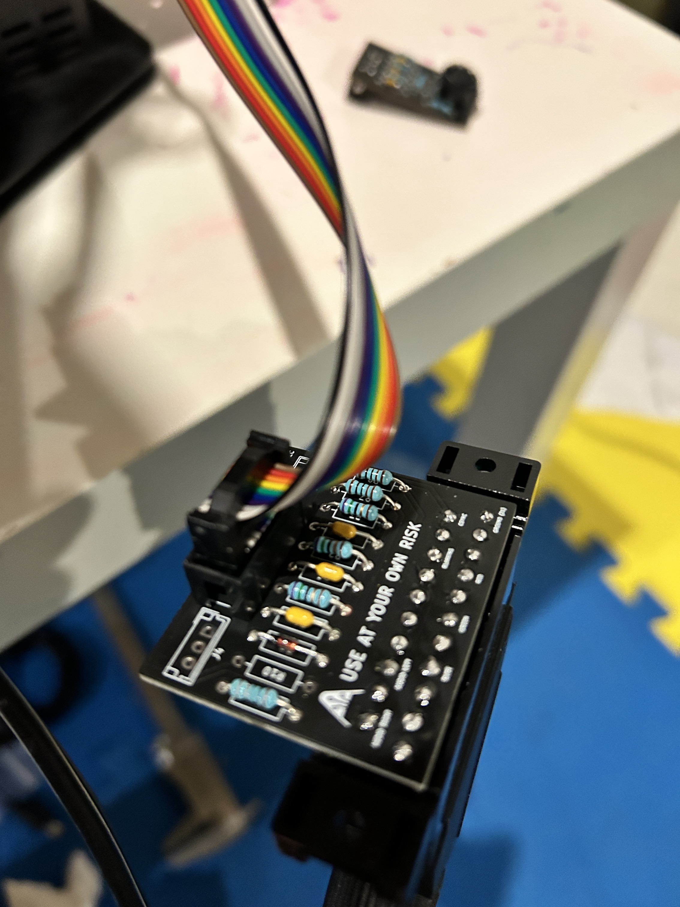
STEP 5: Build your mux board (using the micro RGB board)
This mod uses the RGB mux board. This is optional, but will make your mod easier and stable. You can also create the circuit presented in the schematics above without the board. Please also checkout the mux calculator to play with your own values.
| On Sony CRT Chassis | KV-20S10 |
|---|---|
| 0.1μF caps replaced | No |
| Add diodes on chassis RGB lines? | No |
| Add blanking diode on chassis | Yes |
| RGB mux board | KV-20S10 |
|---|---|
| Mux board RGB termination (R1, R2, R3) | 75Ω |
| Mux board RGB input capacitors (R4, R5, R6) | 0.1μF |
| Mux board Audio LR (R7, R8) | 1kΩ |
| Mux board blanking diode (R9) | 1N4148 |
| Mux board blanking ground resistor (R10) | open |
| Mux board blanking resistor (R11) | 1kΩ |
Compatible mux boards:
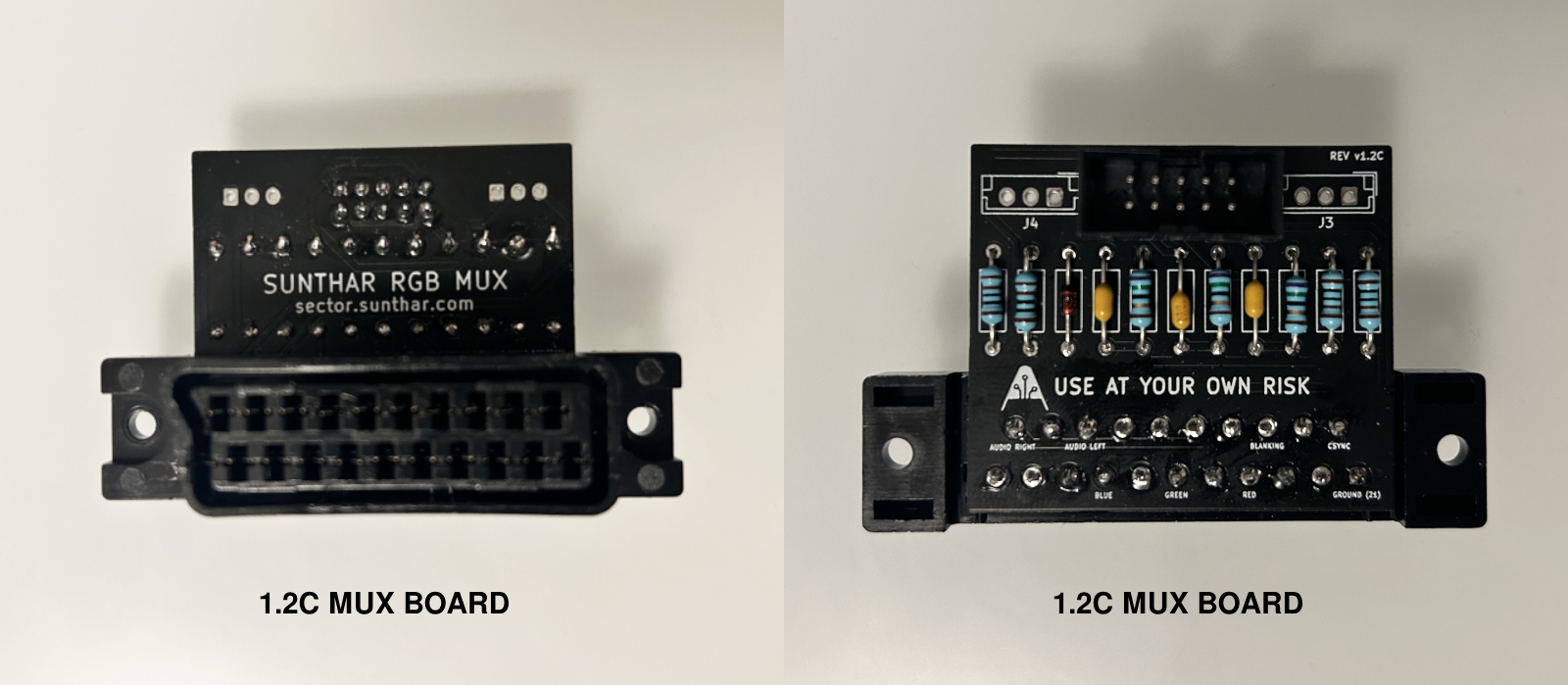
Buy your RGB mux board with the necessary parts to complete this mod
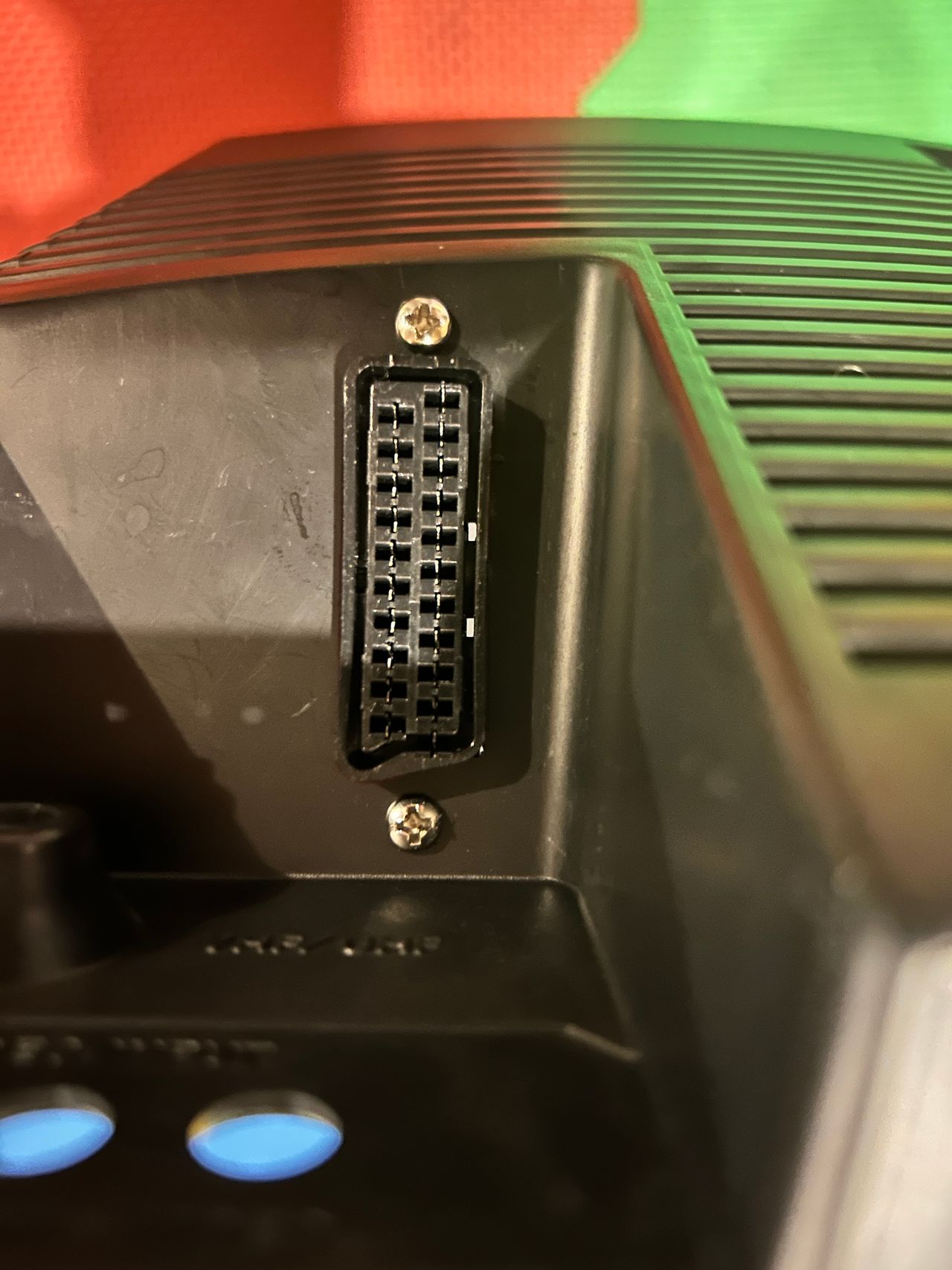
STEP 6: Attach the female SCART connector to TV
I decided to mount the SCART connector on the top part of the input cavity.
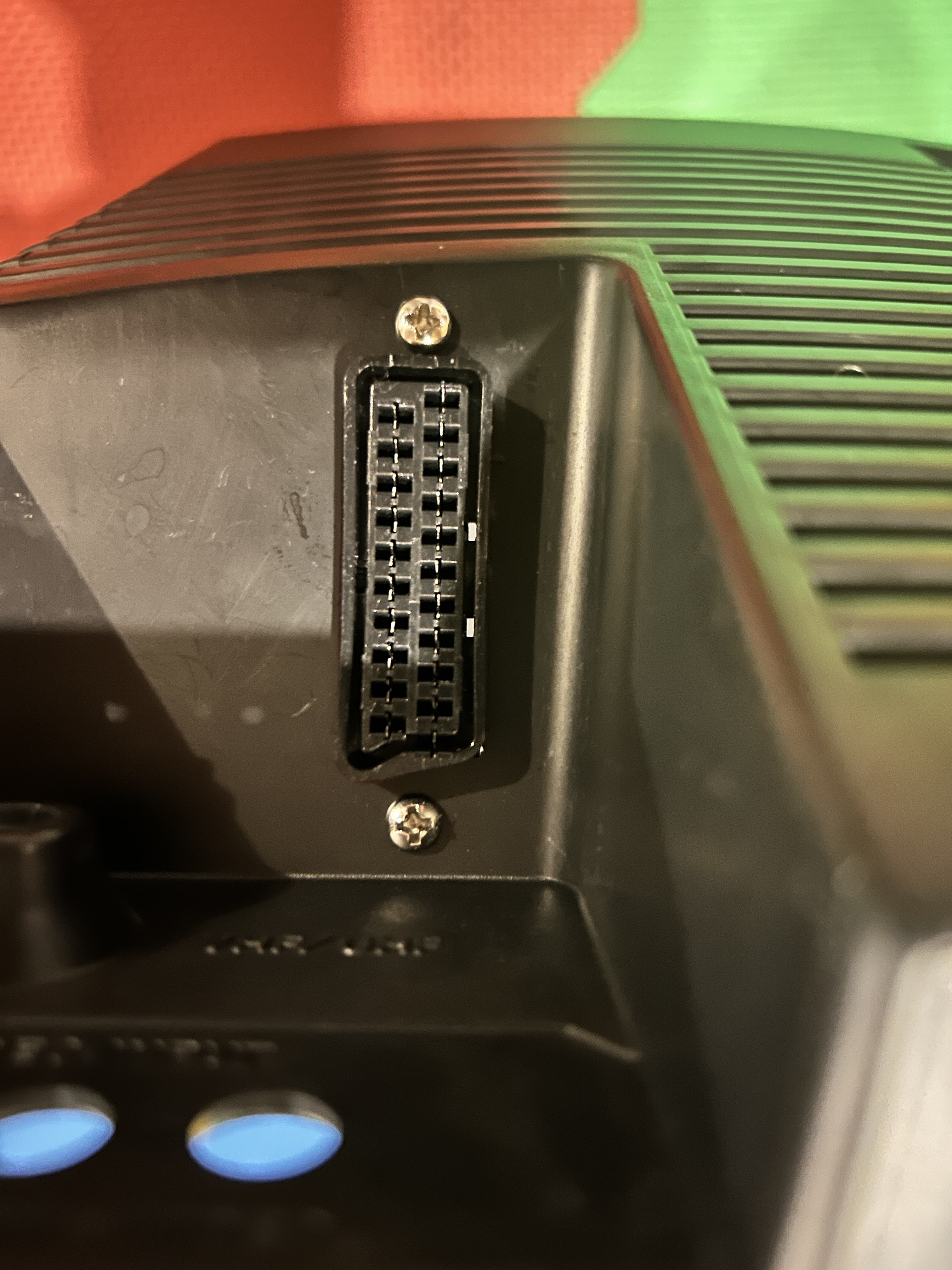
Creating a SCART cutout and mounting it is an art. I have a dedicated section for it.
How to create and mount a SCART female plug?
Service Menu
On the remote, press keys in this sequence DISPLAY, 5, VOL +, POWER
1 and 4 to select 3 and 6 to adjust
MUTING, ENTER to write to memory.
Mux overlay
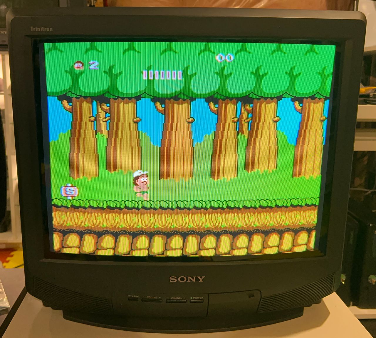
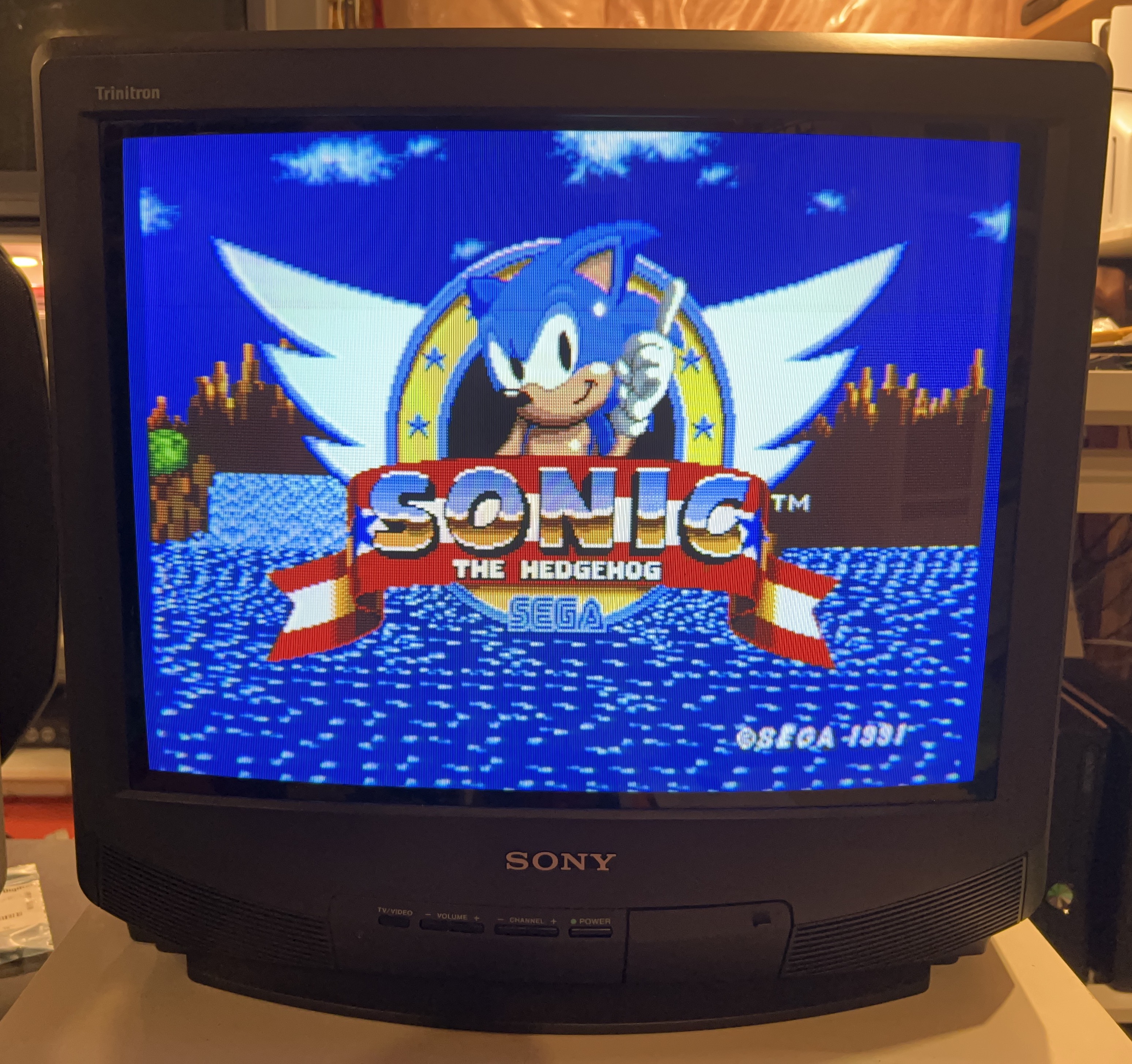
Games
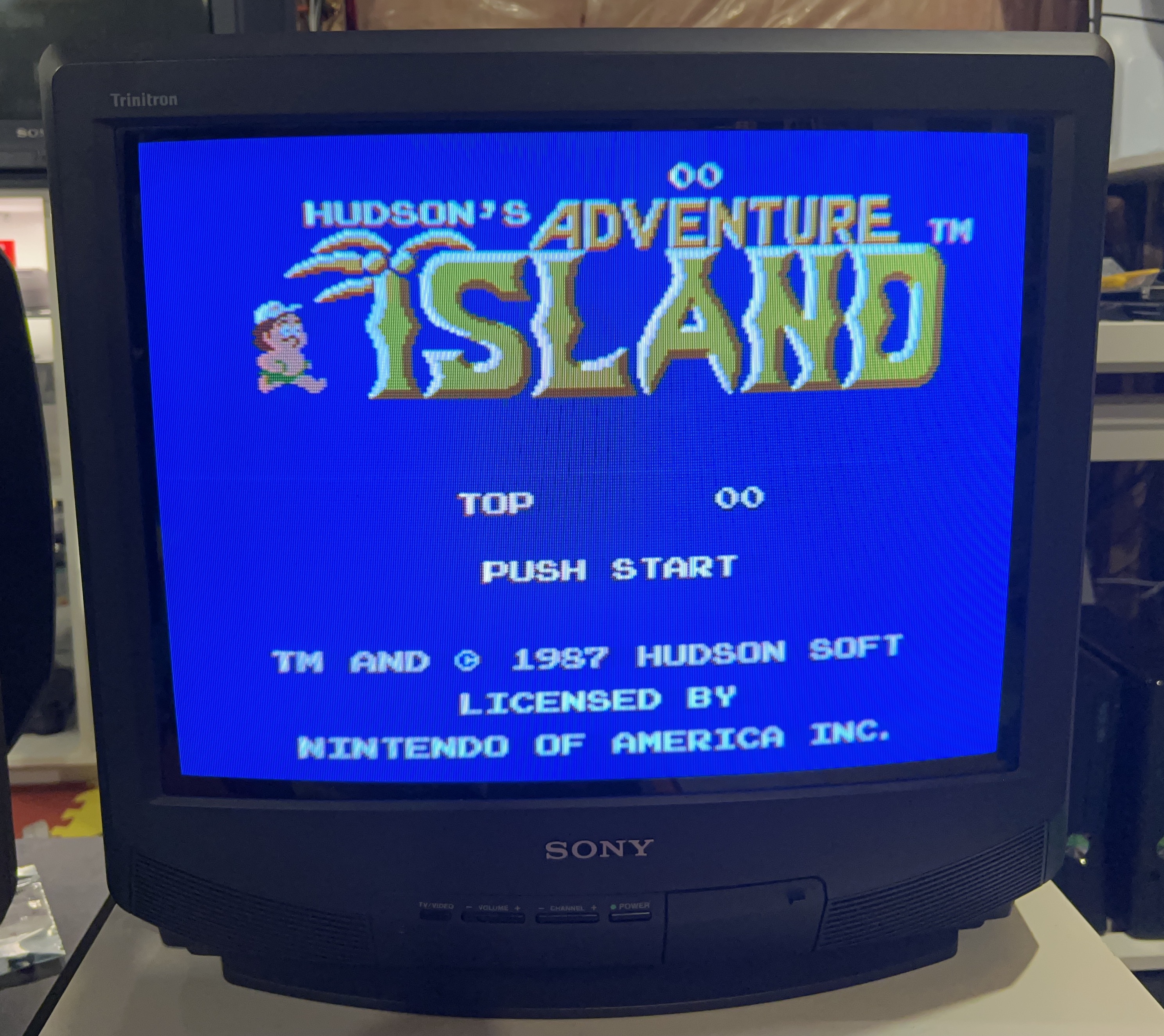
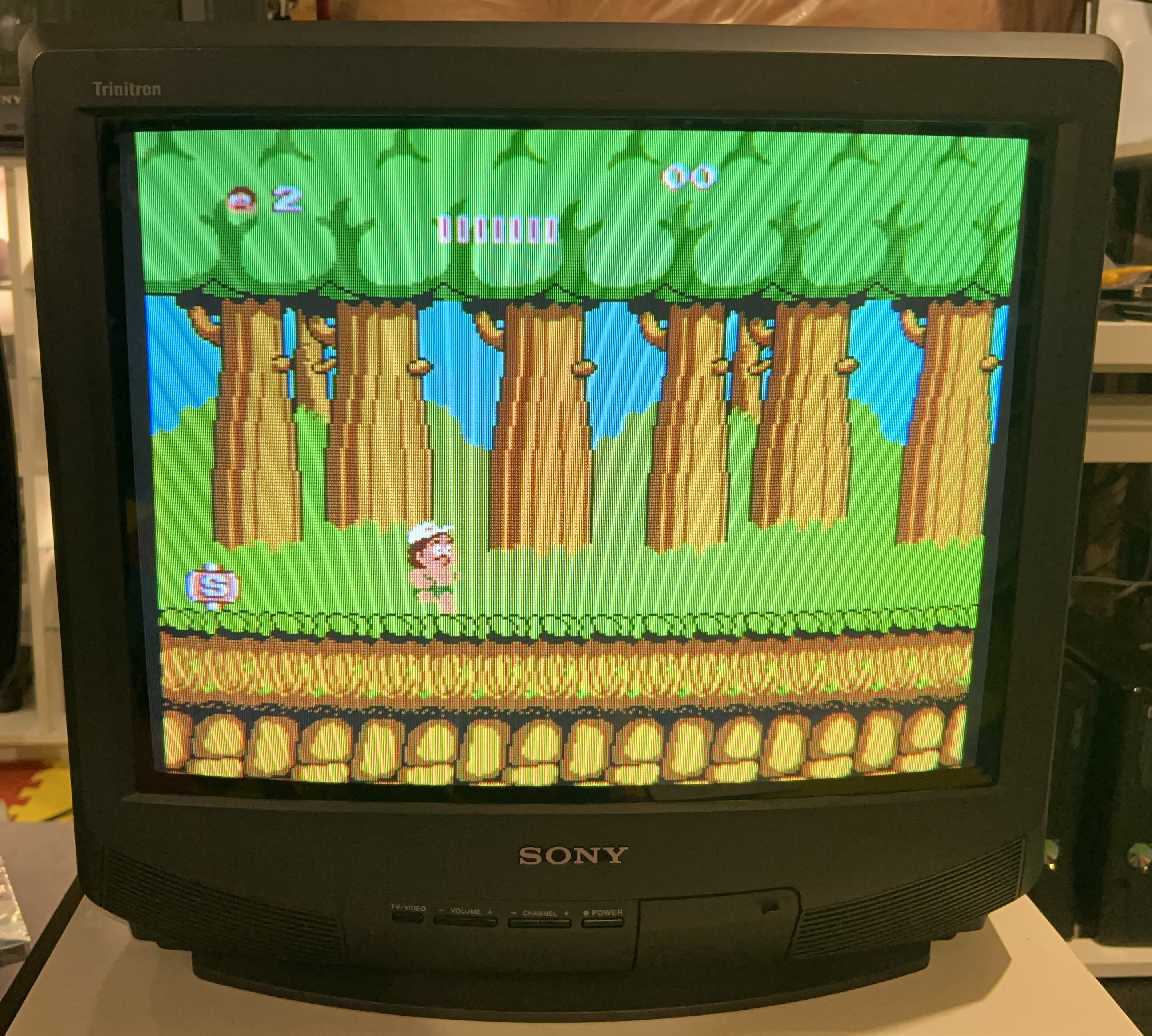
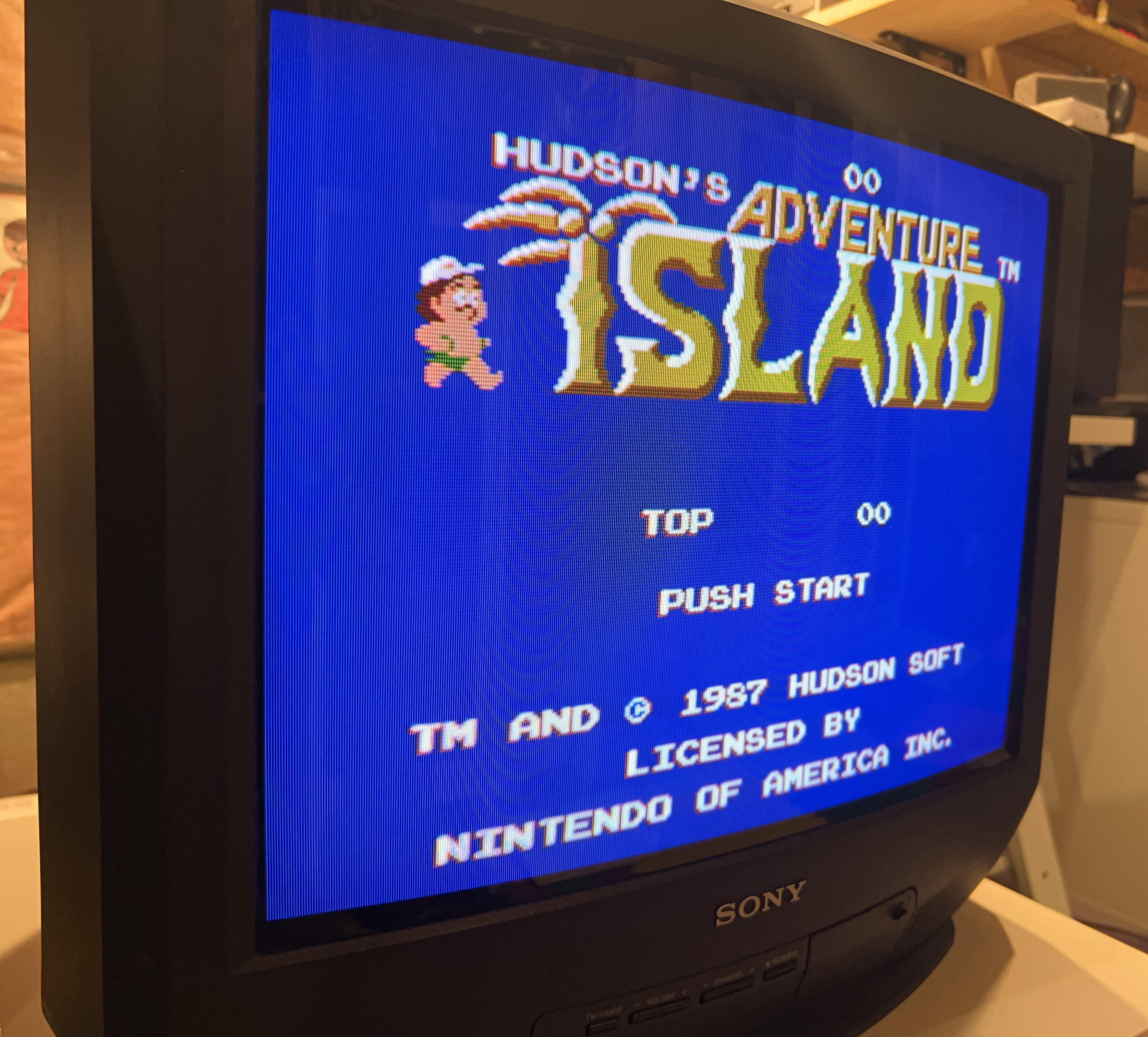
![]()
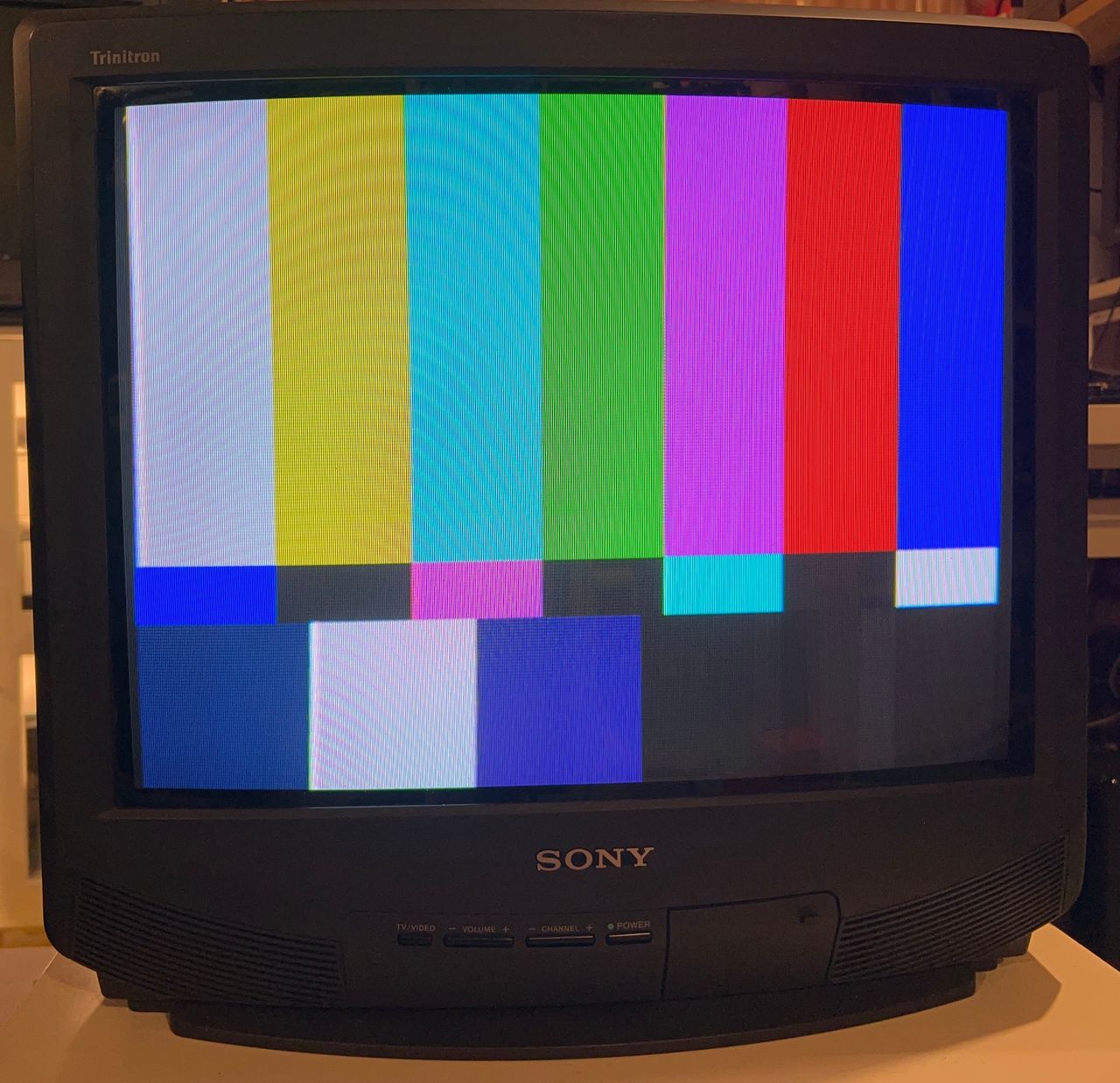
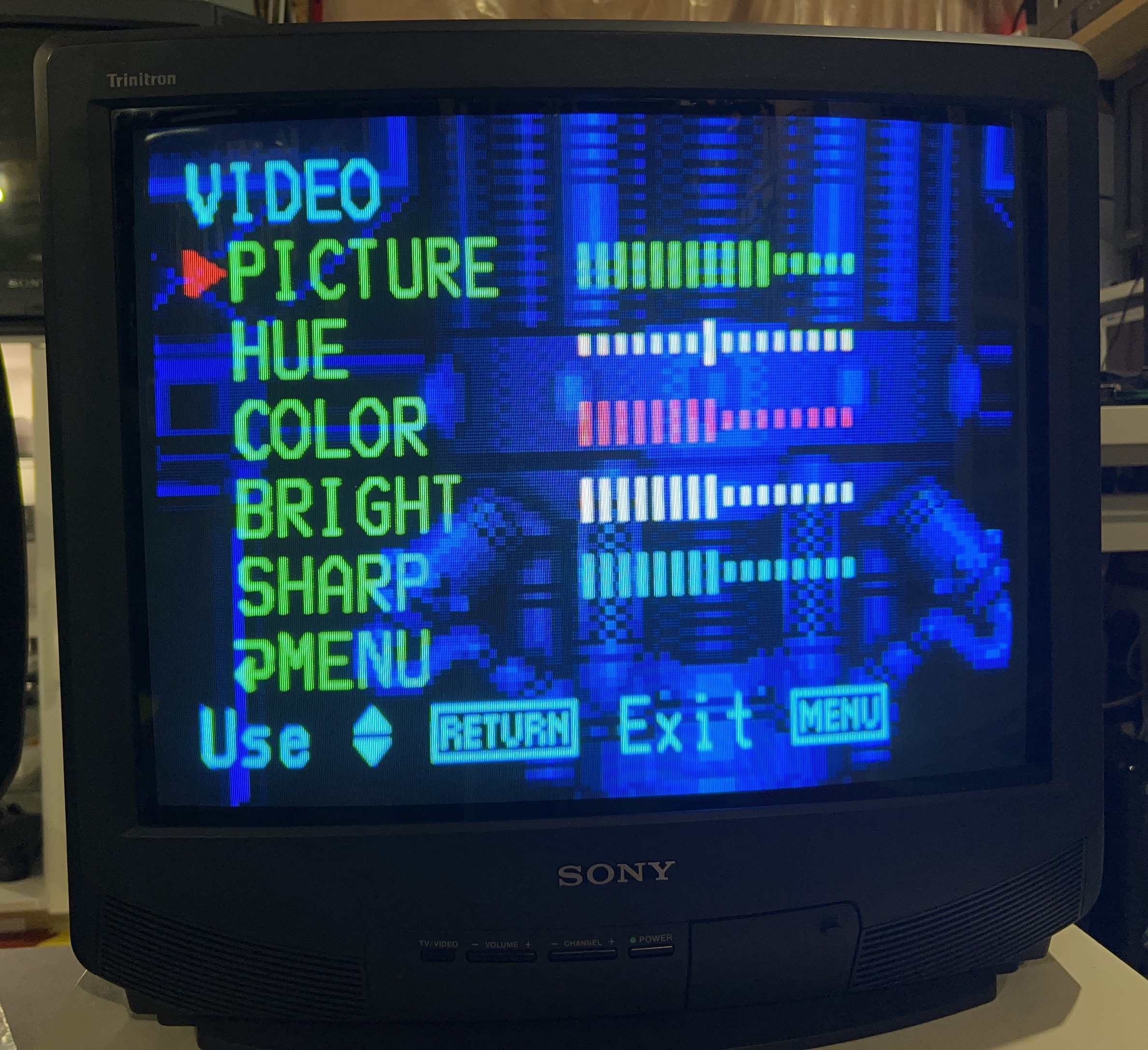
Patterns
RGB Grid 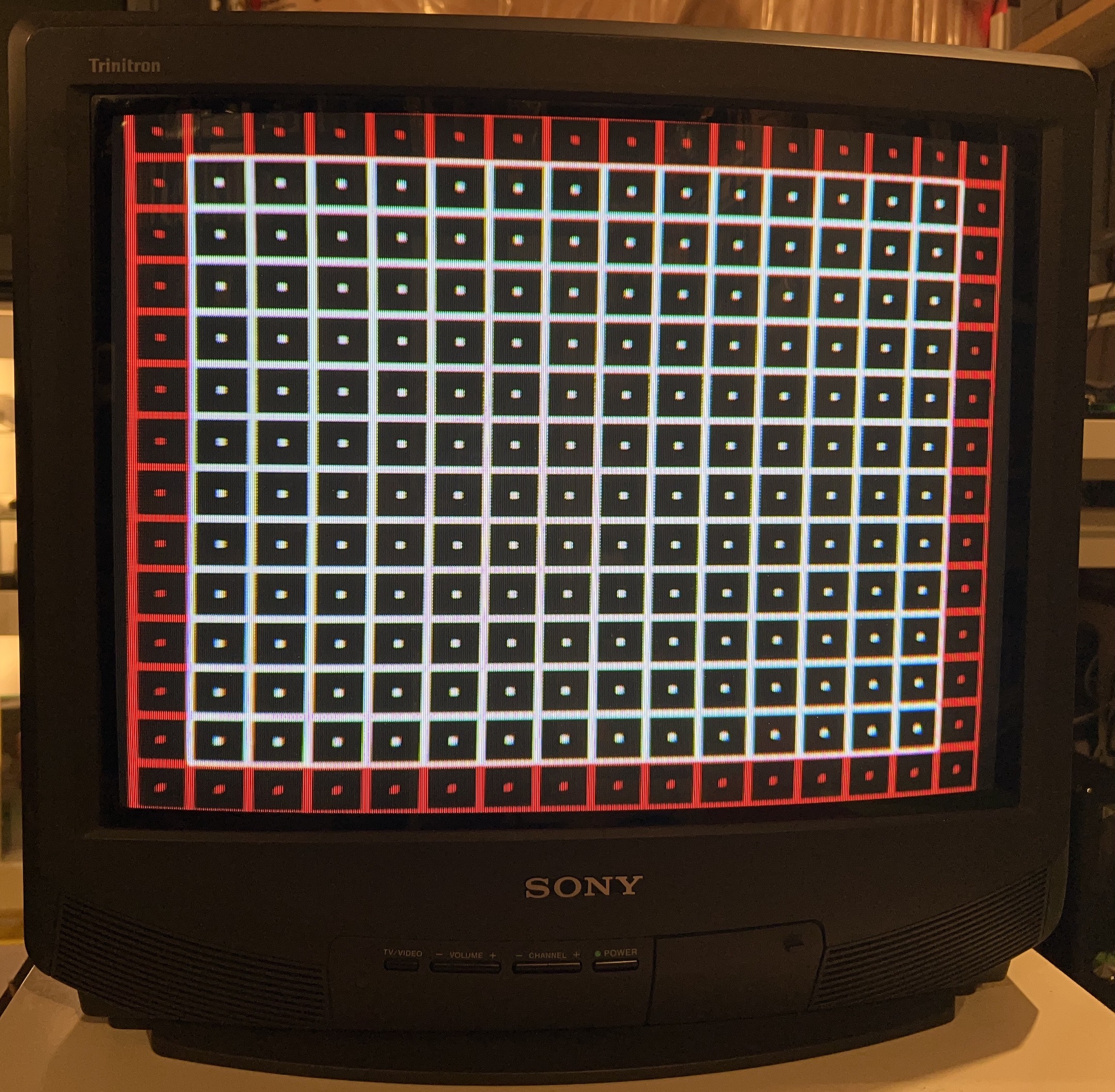
Composite Grid 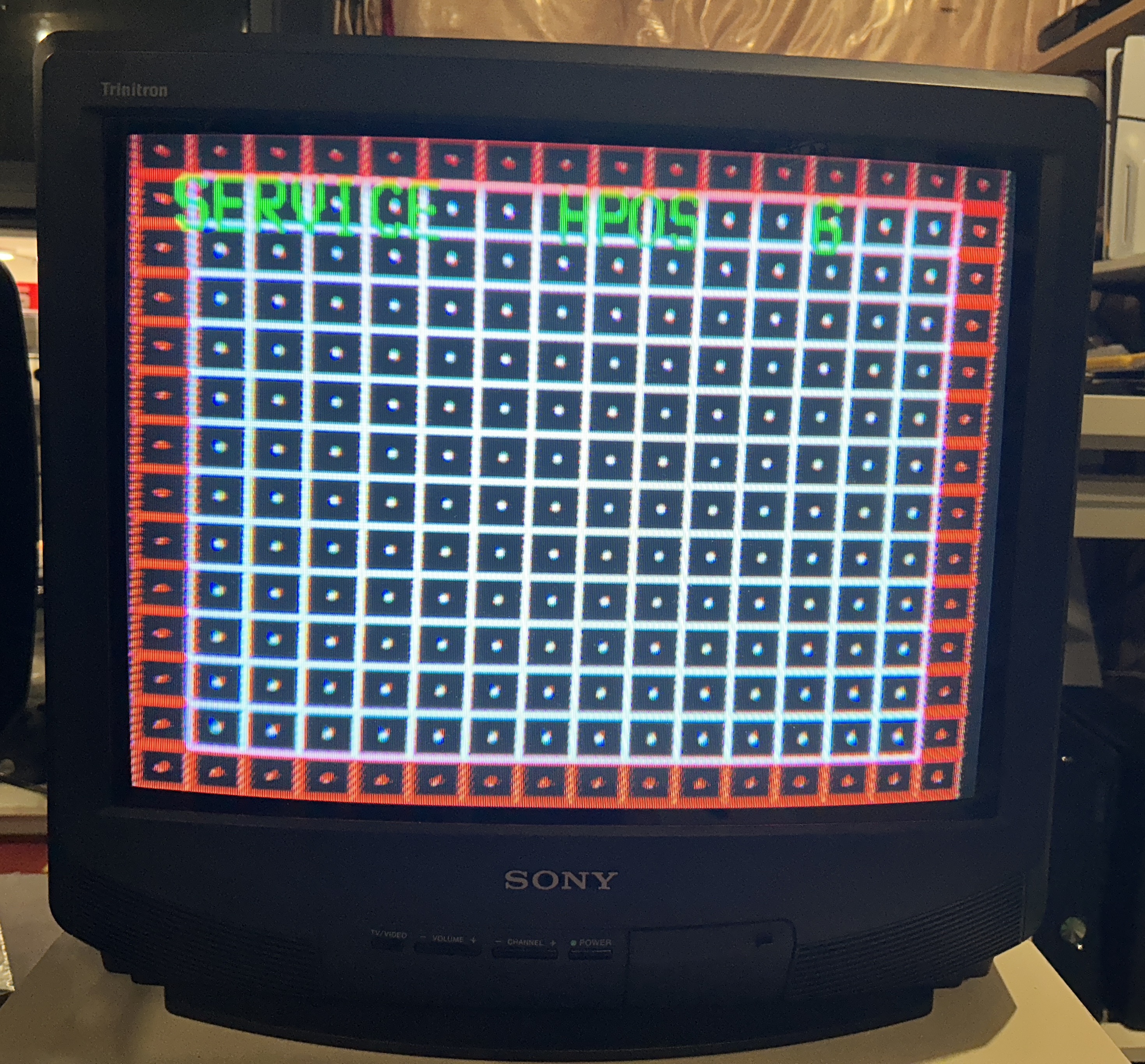
RGB SMPTE 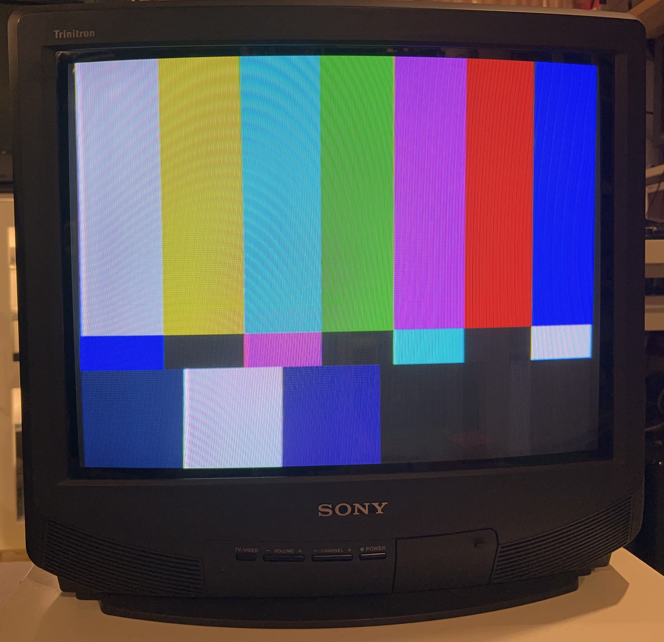
Composite SMPTE 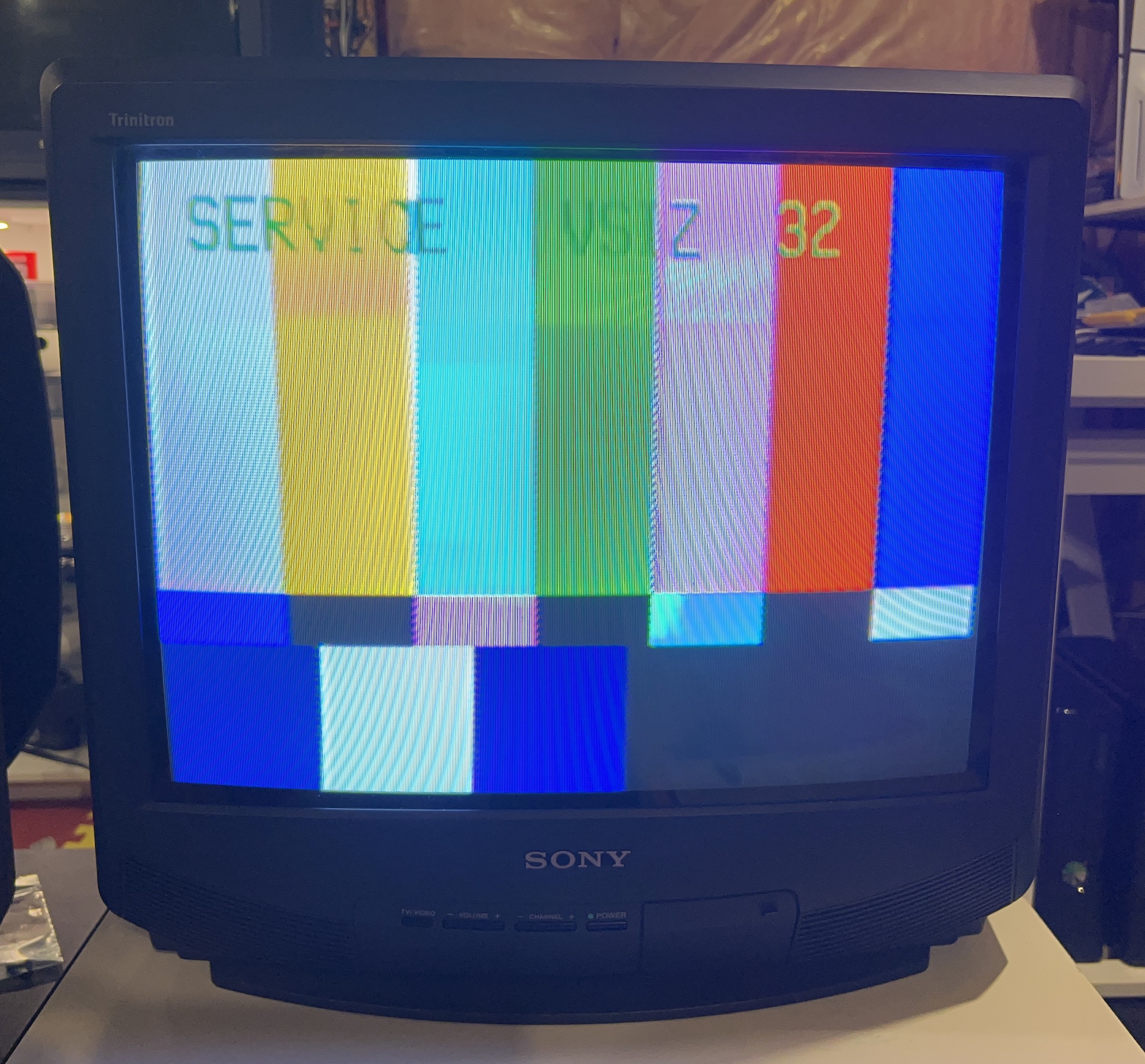
RGB Colors 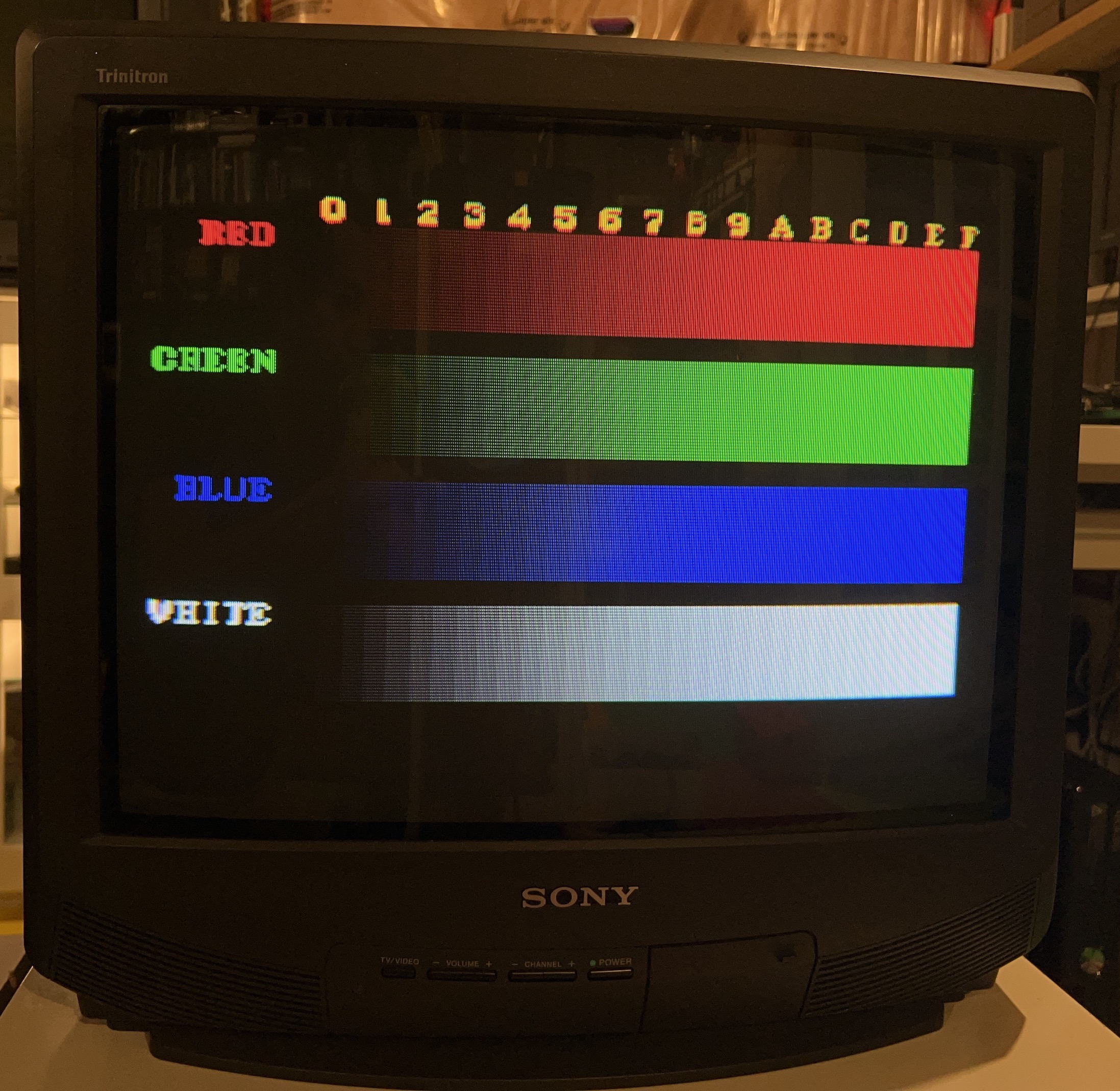
Set
Tube - A51JUH51X 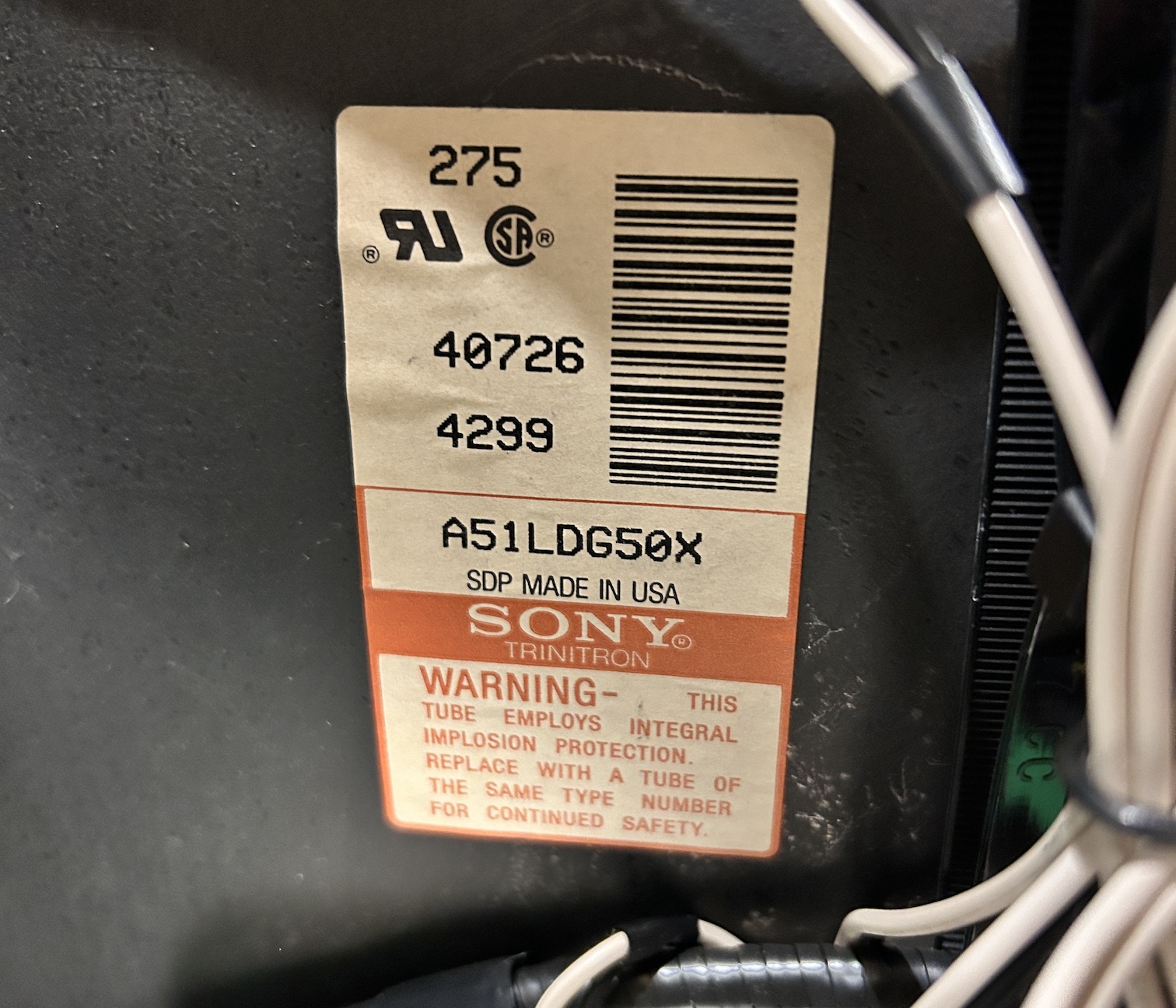
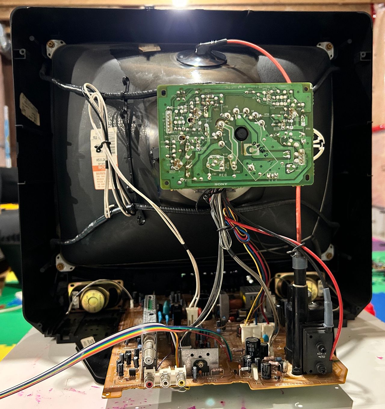
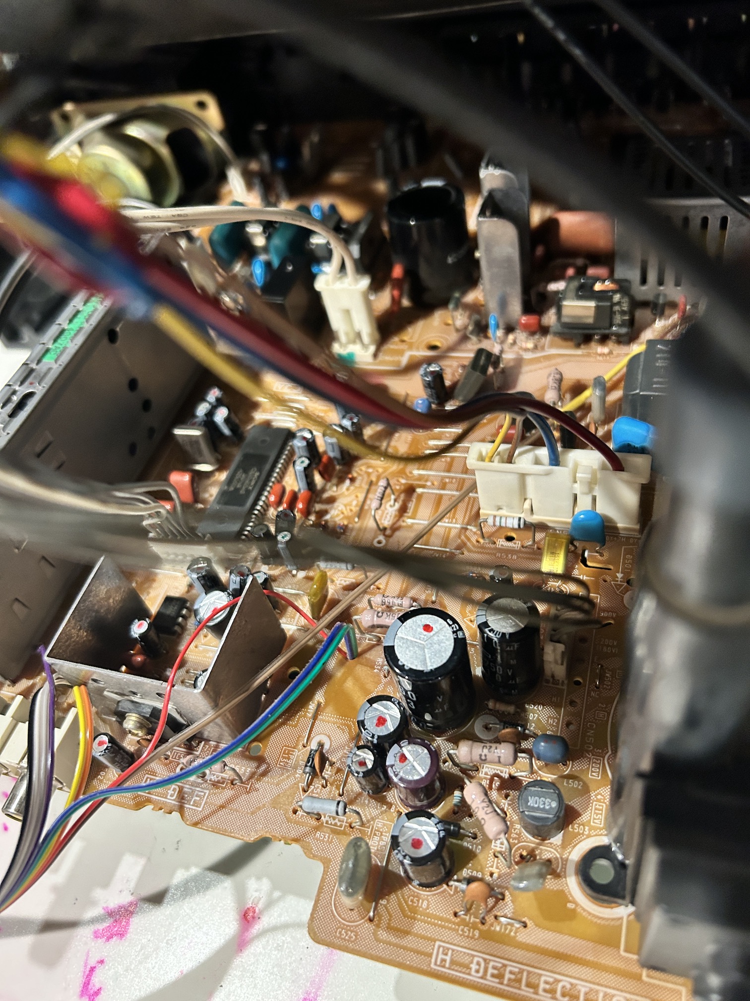
Full Chassis 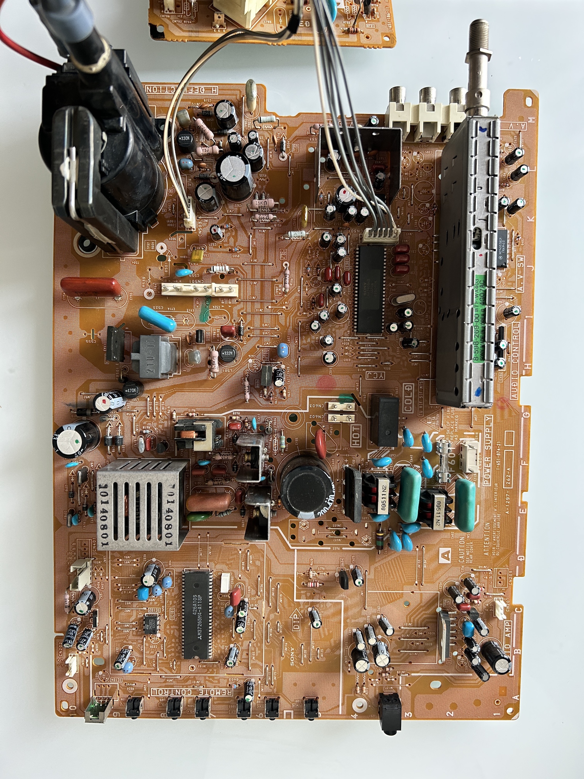
Neck Board 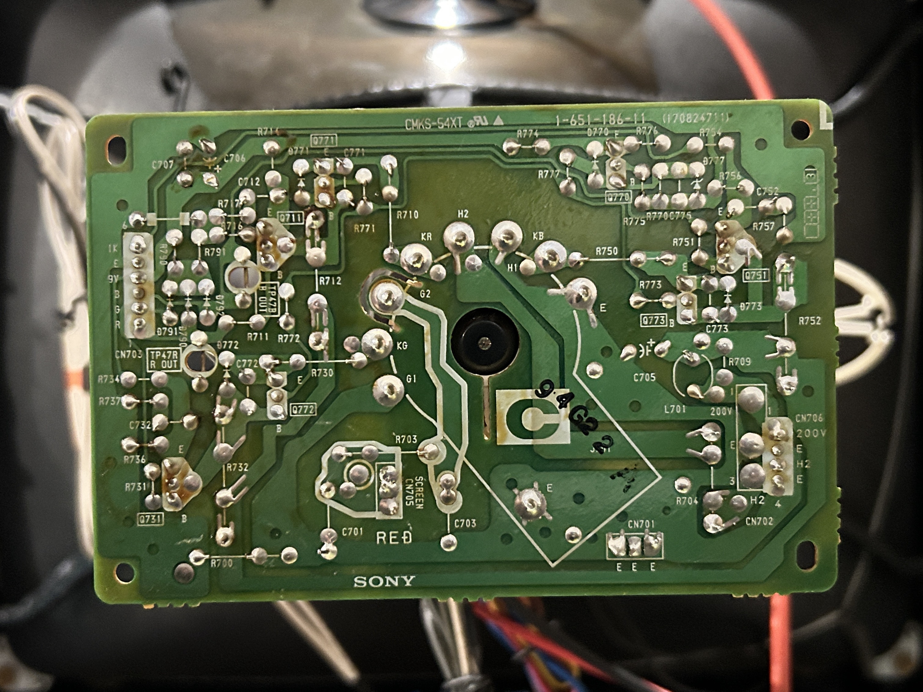
Chroma 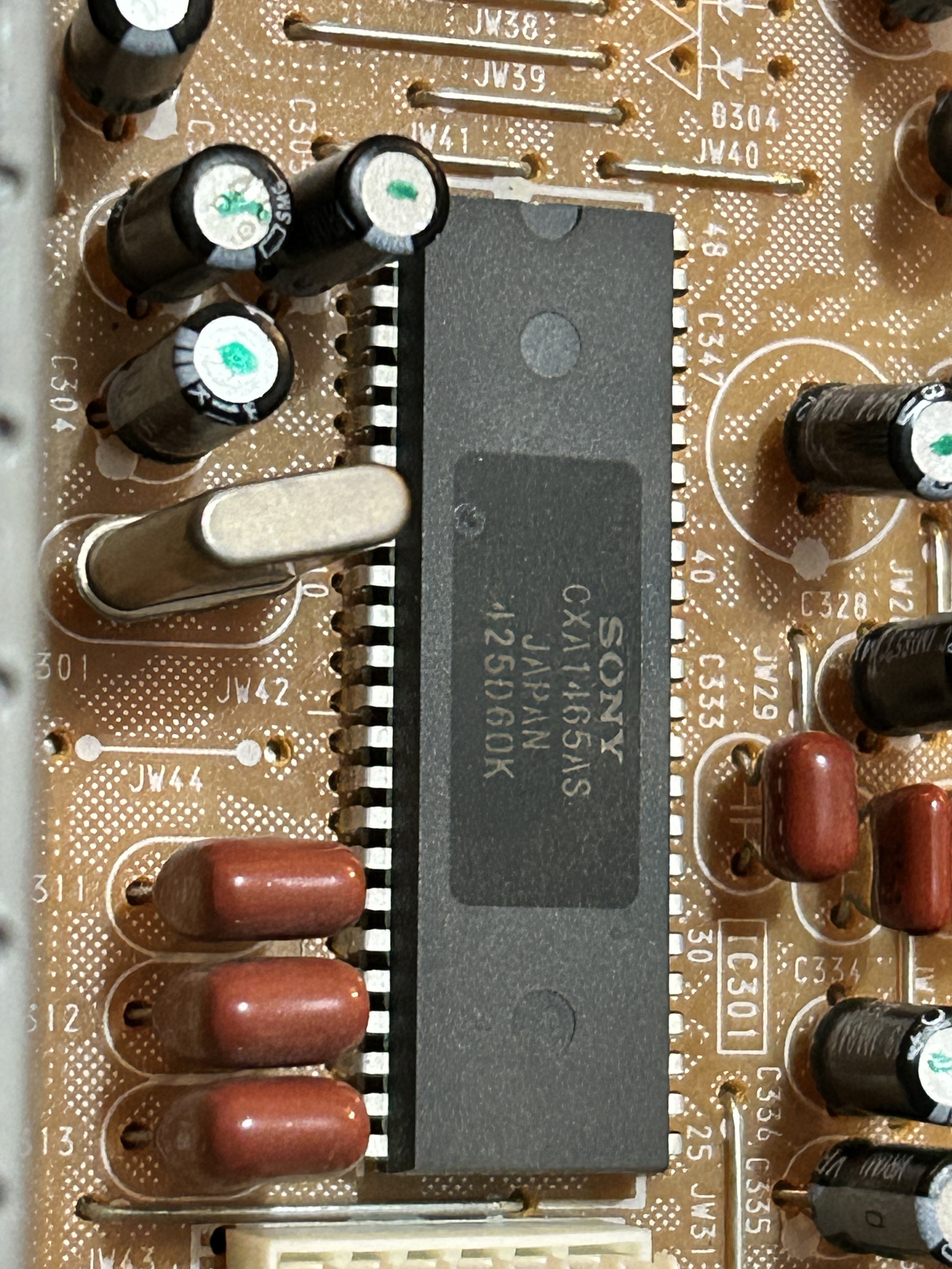
OSD 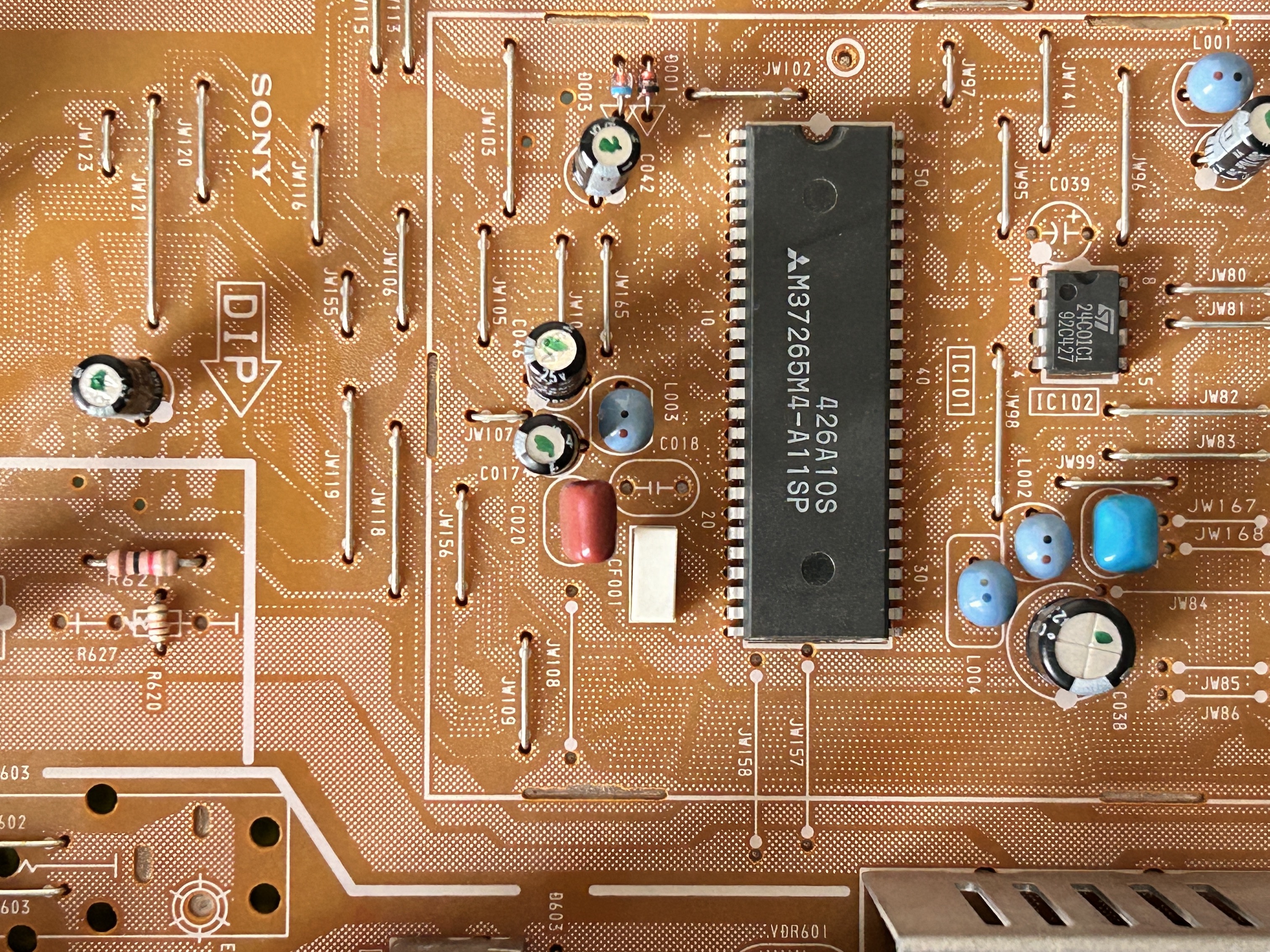
Flyback 
Open Back 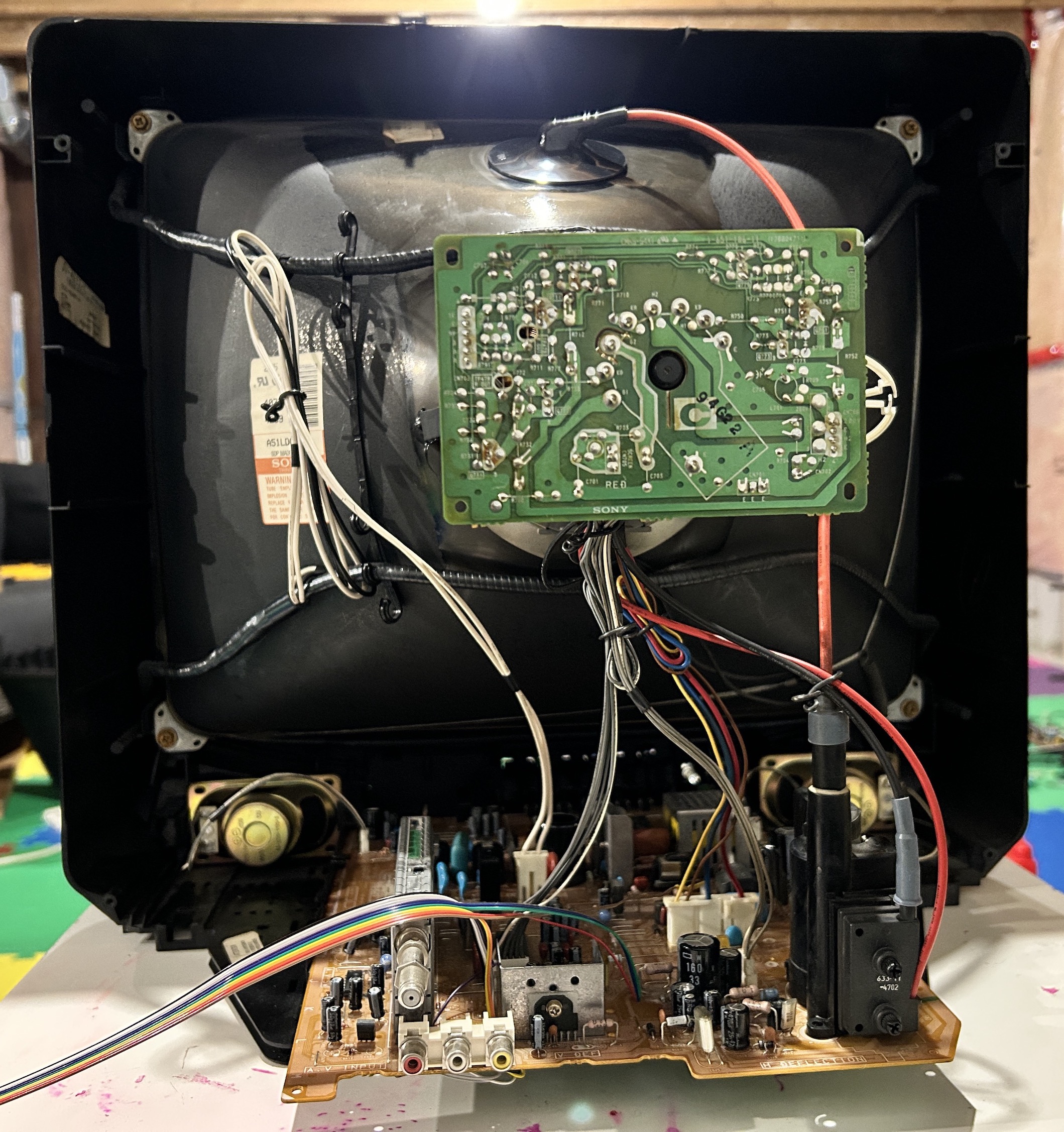
Capacitors
| Region | Cap Location | uF | Voltage | Diameter/Size |
|---|---|---|---|---|
| Power Supply | C609 | 470 | 200 | 25mm |
| Power Supply | C623 | 33 | 160 | 16mm |
| Power Supply | C622 | 1000 | 25 | 10mm |
| Power Supply | C628 | 47 | 25 | 5mm |
| Power Supply | C625 | 100 | 16 | 5mm |
| Neck Board | C706 | 22 | 50 | 5mm |
| Deflection | C527 | 22 | 50 | 5mm |
| Deflection | C520 | 10 | 250 | 10mm |
| Deflection | C522 | 33 | 160 | 16mm |
| Deflection | C515 | 470 | 25 | 10mm |
| Deflection | C514 | 47 | 25 | 5mm |
| Deflection | C528 | 4.7 | 160 | 6.5mm |
| Deflection | C518 | 470 | 25 | 10mm |
| Vertical | C502 | 22 | 50 | 5mm |
| Vertical | C509 | 100 | 50 | 6.5mm |
| Vertical | C517 | 470 | 16 | 10mm |
| Vertical | C506 | 22 | 50 | 5mm |
| Vertical | C530 | 47 | 25 | 5mm |
| Vertical | C513 | 10 | 50 | 5mm |
| Vertical | C511 | 4.7 | 50 | 5mm |
| YCJ | C335 | 1 | 50 | 5mm |
| YCJ | C341 | 0.47 | 50 | 5mm |
| YCJ | C336 | 10 | 50 | 5mm |
| YCJ | C328 | 0.47 | 50 | 5mm |
| YCJ | C347 | 100 | 16 | 5mm |
| YCJ | C345 | 100 | 16 | 5mm |
| YCJ | C324 | 1 | 50 | 5mm |
| YCJ | C319 | 0.47 | 50 | 5mm |
| YCJ | C315 | 220 | 16 | 5mm |
| YCJ | C310 | 22 | 50 | 5mm |
| YCJ | C305 | 1 | 50 | 5mm |
| YCJ | C308 | 0.47 | 50 | 5mm |
| YCJ | C304 | 10 | 50 | 5mm |
| A/V Input | C403 | 10 | 50 | 5mm |
| A/V Input | C404 | 100 | 16 | 5mm |
| A/V Switch | C631 | 47 | 25 | 5mm |
| A/V Switch | C406 | 1 | 50 | 5mm |
| A/V Switch | C407 | 1 | 50 | 5mm |
| A/V Switch | C401 | 10 | 50 | 5mm |
| A/V Switch | C204 | 100 | 16 | 5mm |
| A/V Switch | C410 | 10 | 50 | 5mm |
| A/V Switch | C402 | 1 | 50 | 5mm |
| A/V Switch | C401 | 1 | 50 | 5mm |
| Audio Control | C409 | 10 | 50 | 5mm |
| Audio Control | C412 | 10 | 50 | 5mm |
| Audio Control | C101 | 4.7 | 50 | 5mm |
| Remote Control | C531 | 47 | 25 | 5mm |
| Remote Control | C408 | 10 | 50 | 5mm |
| Remote Control | C042 | 1 | 50 | 5mm |
| Remote Control | C046 | 47 | 25 | 5mm |
| Remote Control | C017 | 1 | 50 | 5mm |
| Remote Control | C632 | 10 | 50 | 5mm |
| Remote Control | C038 | 470 | 16 | 8.3mm |
| Remote Control | C691 | 470 | 16 | 8.3mm |
| Remote Control | C692 | 47 | 25 | 5mm |
| Remote Control | C690 | 0.47 | 50 | 5mm |
Service Menu Settings
| Name | Default |
|---|---|
| AFC | 0 |
| VFRE | 16 |
| VPOS | 21 |
| VSIZ | 31 |
| VLIN | 8 |
| VSCO | 6 |
| HPOS | 6 |
| VCOM | 2 |
| GAMP | 21 |
| BAMP | 14 |
| GCUT | 6 |
| BCUT | 7 |
| CROM | 26 |
| SPIX | 30 |
| SHUE | 25 |
| SCOL | 30 |
| SBRT | 24 |
| SVOL | 0 |
| SHAp | 7 |
| VSMO | 0 |
| REF | 2 |
| ROFF | 1 |
| GOFF | 1 |
| BOFF | 1 |
| ABLM | 1 |
| NOTC | 0 |
| DRGB | 0 |
| DISP | 4 |
| PADJ | 43 |
| ID0 | 64 |
| ID1 | 9 |
| ID2 | 64 |
| ID3 | 1 |
| ID4 | 16 |
Pictures
Reference Photos