Sanyo AVM-20F5
Sanyo AVM-20F5 CRT RGB mod
Is it possible to restore a CRT that went through a poor RGB mod? Let's find out. This tutorial covers the RGB mod for Sanyo AVM-20F5 (Flat 20", Sanyo CRT). These instructions should also work for the below CRTs.
The Sanyo AVM-20F5 is a 20" CRT television released around 2003, often used for retro gaming due to its flat screen, decent image quality, and inclusion of S-Video.
This set is RGB moddable.
View full CRT details and more mod examples →
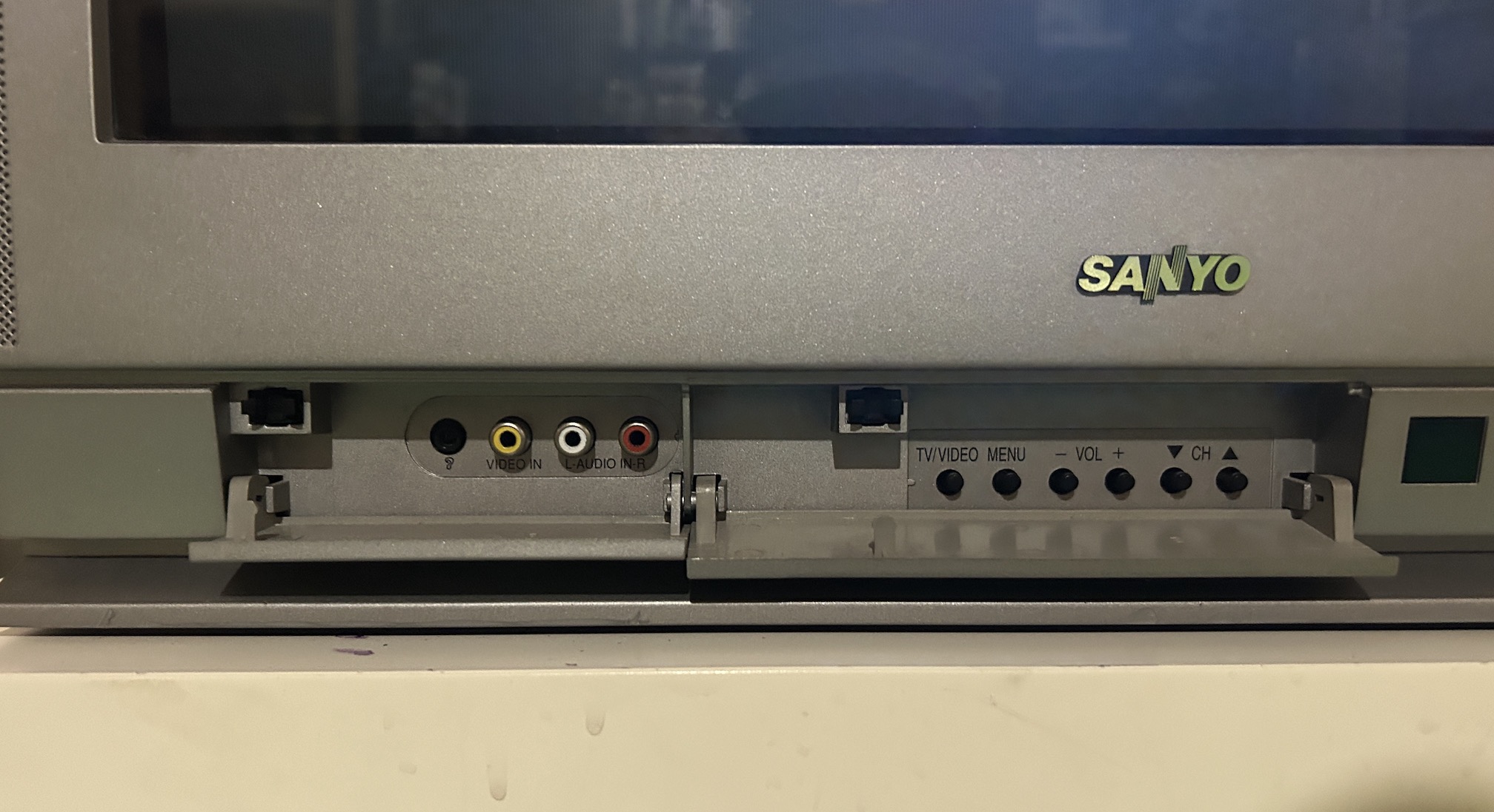
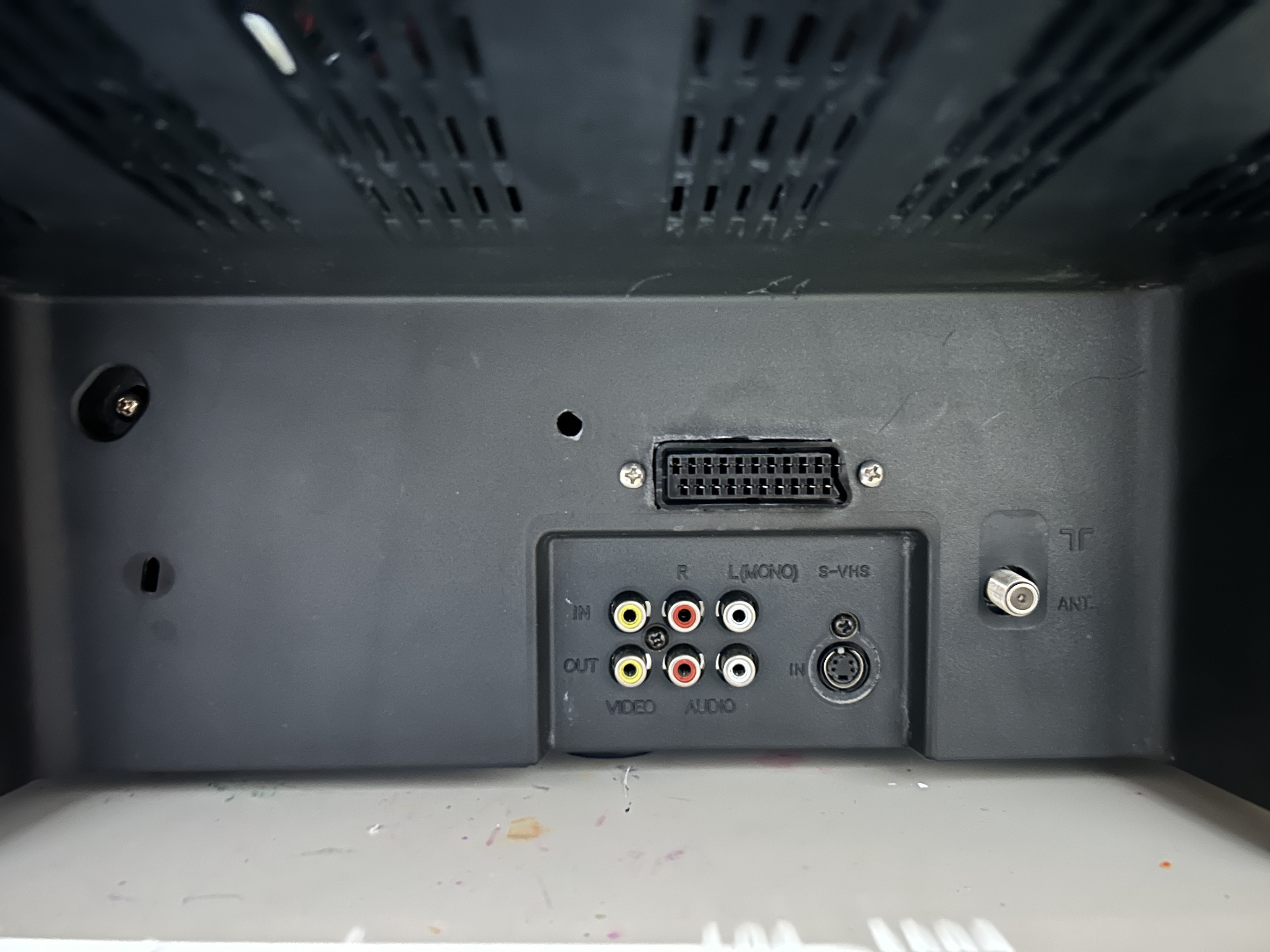
Given that this CRT TV solely features one composite input at the front, two composite inputs, one s-video input, and an RF input at the back, it's certainly worthwhile to modify it for RGB input. Although a few adjustments are required, the modification process employs the standard mux mod.
Backstory of the Sanyo CRT
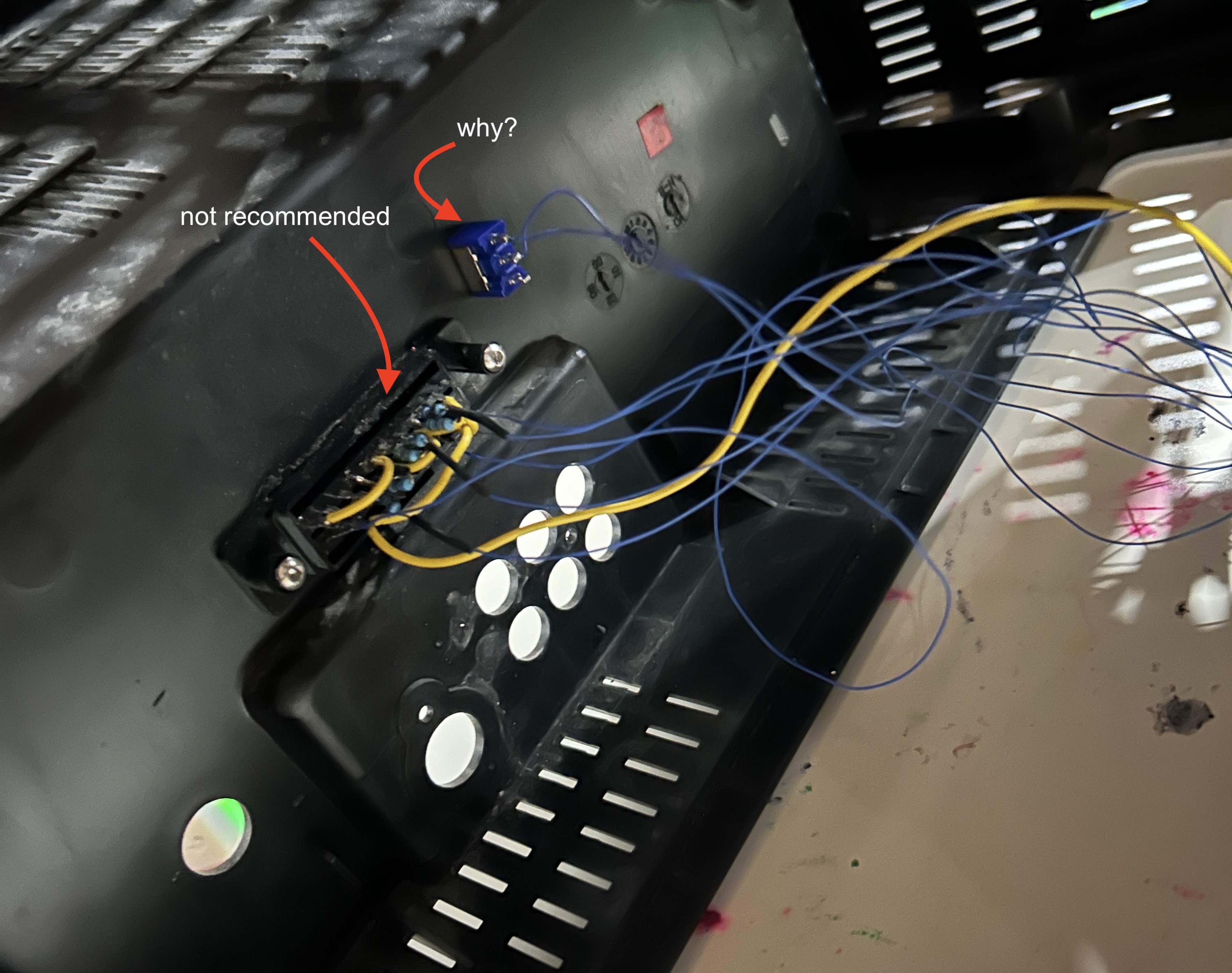
Someone who purchased two RGB modded CRT tvs from me wanted their Sanyo CRT tv looked at. Upon initial inspection there was a heavy red tint. When we tried to get into the service menu, suddenly the CRT stopped working. It went into HV protection mode. Tube and the chassis were in great condition. This Sanyo CRT tv had undergone prior modifications by an individual, but the RGB mod was executed inaccurately. It was a bit challenging to take the back cover off, since everything was glued in place with no easy way to disconnect. Upon further inspection the problem was found to be poor RGB modding, incorrect resistor values and shorting of some pins. While the simplicity of just soldering the resistors directly to the SCART connector can be admired, sometimes it can cause more headache than what it's worth. I highly recommend you order the PCB with quick disconnect, so that you can easily service the CRT when needed.
Contributors
Thank you to everyone who contributed to this guide:
- Sunthar — contributor, RGB mod and pictures
CRT safety
Caution
You can die doing this! So read carefully! CRT TV is not a toy. Do not open a CRT TV. If you don't have any prior knowledge about handling high voltage devices, this guide is not for you. CRT TV contains high enough voltage (20,000+ V) and current to be deadly, even when it is turned off.
Plan of attack
Manuals and Datasheets
Calculating the RGB external resistor value
Love it when we can put theories to use! Formula from our theory page!
We find out using ohms law, this CRT is using ~0.7Vp-p. How?
Vp-p = 5V x (680/(4700+680)) = 5V x 0.1264 = 0.63V

RGB external resistor value
= (0.7 x (4700 + 75) - (75 x 5)) / (5 - 0.7)
= (0.7 x 4775 - 375) / 4.3
= 2967 / 4.3
= 690Ω
680Ω resistors should do the job. One thing to keep in mind is that the external resistor value calculated is typically very close to the resistor value removed.
Specs
- Manufactured: USA ()
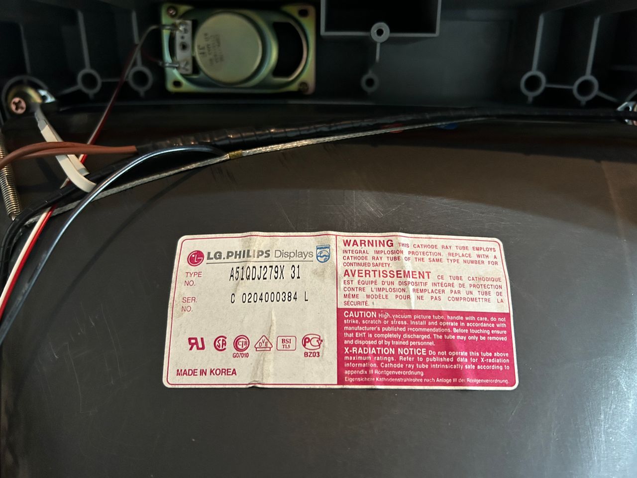
- Tube: LG A51QDJ279X
- Jungle Chip: Toshiba TB1231CN
- OSD Chip: KEC KMPA8701CMN-3B14
- Screen Size: 20"
RGB mux diagram
Prepare the mux diagram. If you are building your own circuit, this diagram should help.
Performing the mod
Now that you roughly know what needs to be done, prepare for the mod. Place the board on a comfortable place. Make sure you are not putting pressure on the flyback or other components.
STEP 1: Remove the following components
Remove the following components. RGB resistors to the ground. Measure twice and mark before you remove.
- R007 (680Ω)
- R008 (680Ω)
- R009 (680Ω)
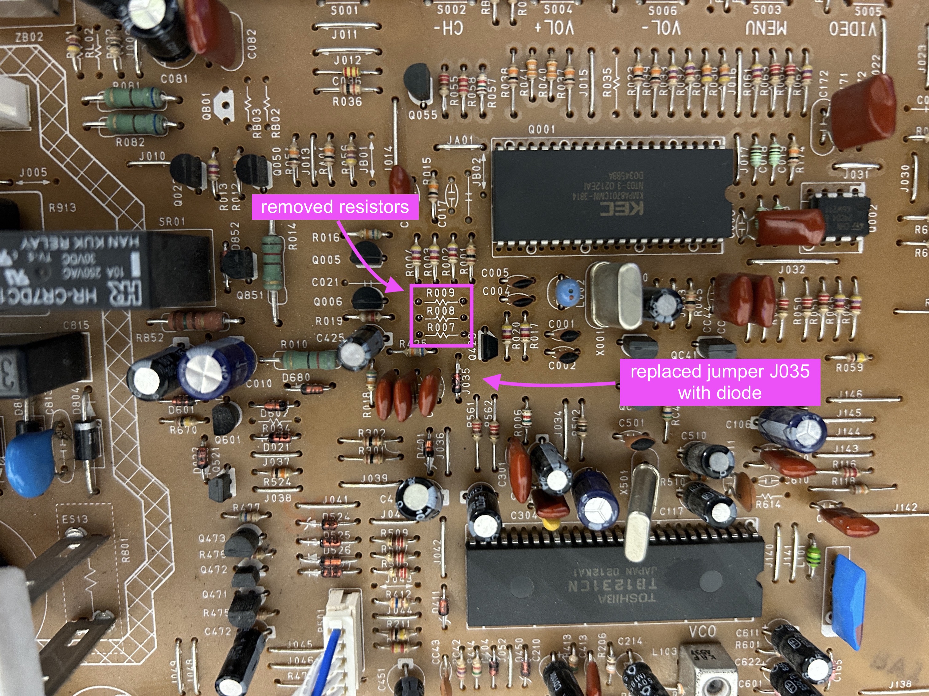
STEP 2: Blanking diode
To prevent current from flowing back into the OSD and causing interferences in RGB mods, it's necessary to include a diode in the blanking line. The absence of this diode is the main cause of such issues.
Replace jumper J035 with a diode 1N4148. Pay attention to the direction of the diode.
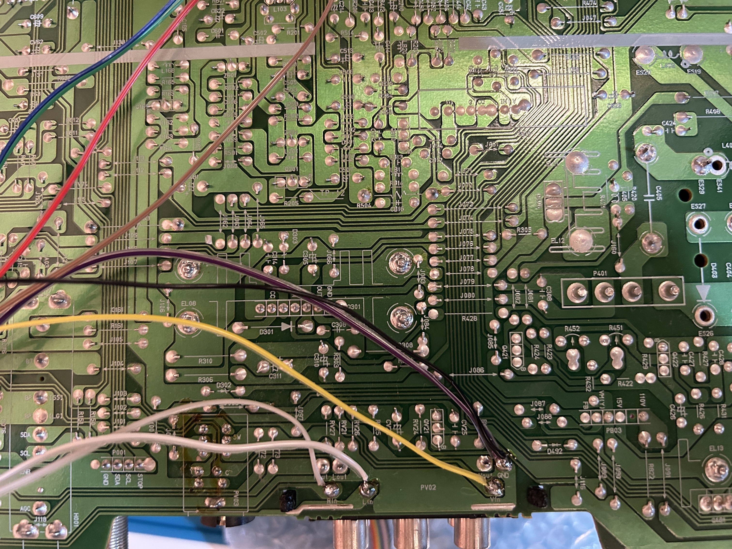
STEP 3: Connect RGB, Blanking
Refer to the picture below to connect the RGB and blanking wires. Be sure to solder them to the leg of the resistor that is facing away from the OSD chip.
![]()
STEP 4: Sync and Audio
Sync and Audio can be connected to the Video input.
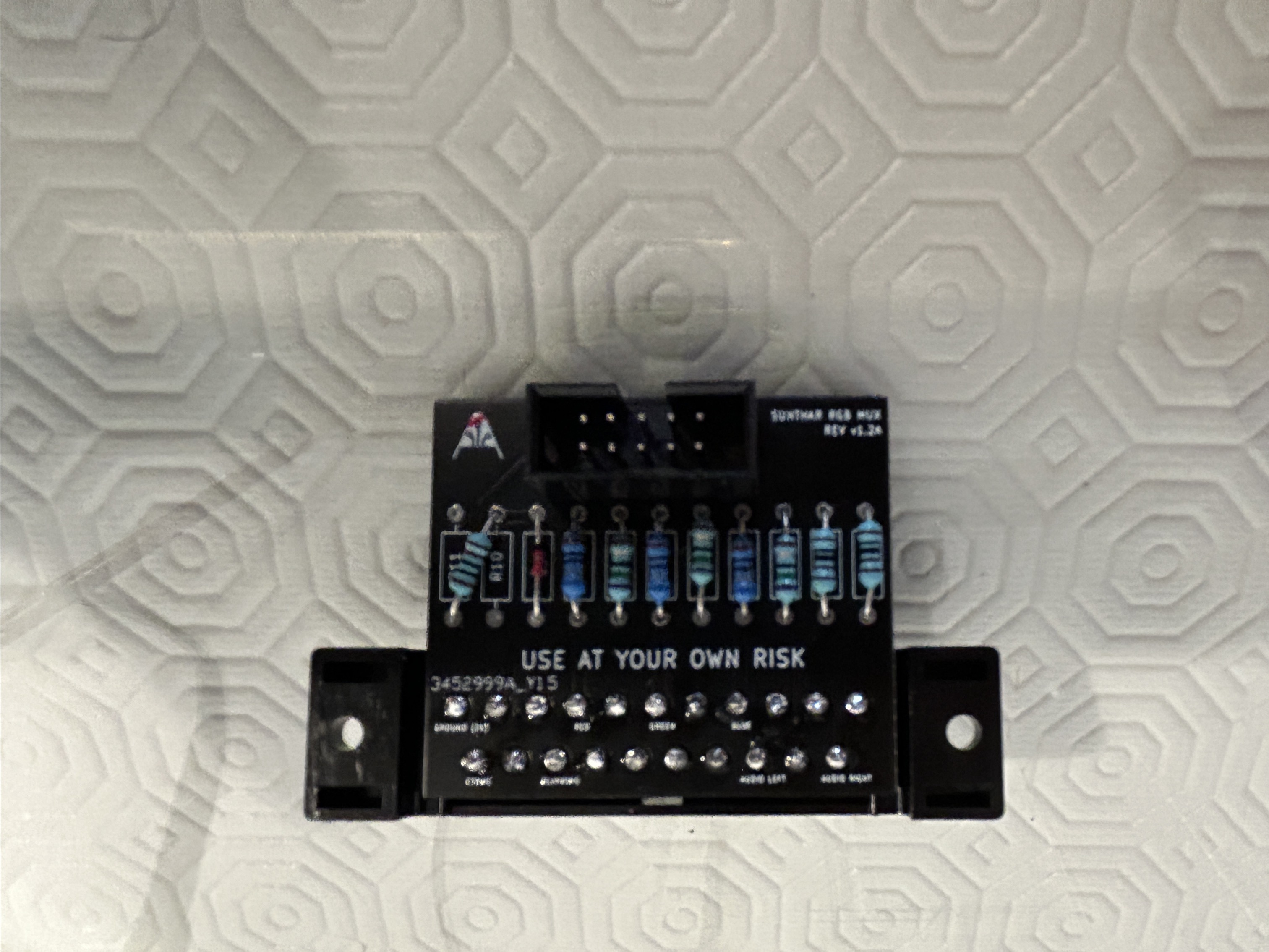
STEP 5: Build your mux board
This mod uses the RGB mux board. This is optional, but will make your mod easier and stable. You can also create the circuit presented in the schematics above without the board. Please also checkout the mux calculator to play with your own values.
| On Sanyo CRT Chassis | AVM-20F5 |
|---|---|
| CRT RGB inline resistor | 4.7kΩ |
| CRT RGB ground resistors removed | 680Ω |
| 0.1μF caps replaced | Yes |
| Add RGB diodes on chassis | No |
| Add blanking diode on chassis | Yes |
| RGB mux board | AVM-20F5 |
|---|---|
| Mux board RGB termination (R1, R2, R3) | 220Ω |
| Mux board RGB inline resistors (R4, R5, R6) | 680Ω |
| Mux board Audio LR (R7, R8) | 1kΩ |
| Mux board blanking diode (R9) | 1N4148 |
| Mux board blanking ground resistor (R10) | 1kΩ |
| Mux board blanking resistor (R11) | short |
Compatible mux boards:
To add a blanking diode, replace J035. Direction of the diode matters.
Although the calculations were helpful, a dedicated tuner board was utilized to identify the optimal combination of RGB inline and termination resistance required to achieve the ideal color balance. After testing, it was discovered that a 220Ω termination provided the finest RGB image.
STEP 6: Attach the female SCART connector to TV
Creating a SCART cutout and mounting it is an art. I have a dedicated section for it.
How to create and mount a SCART female plug?
OSD overlay on top of PS1 boot logo showing the mux mod is working well. 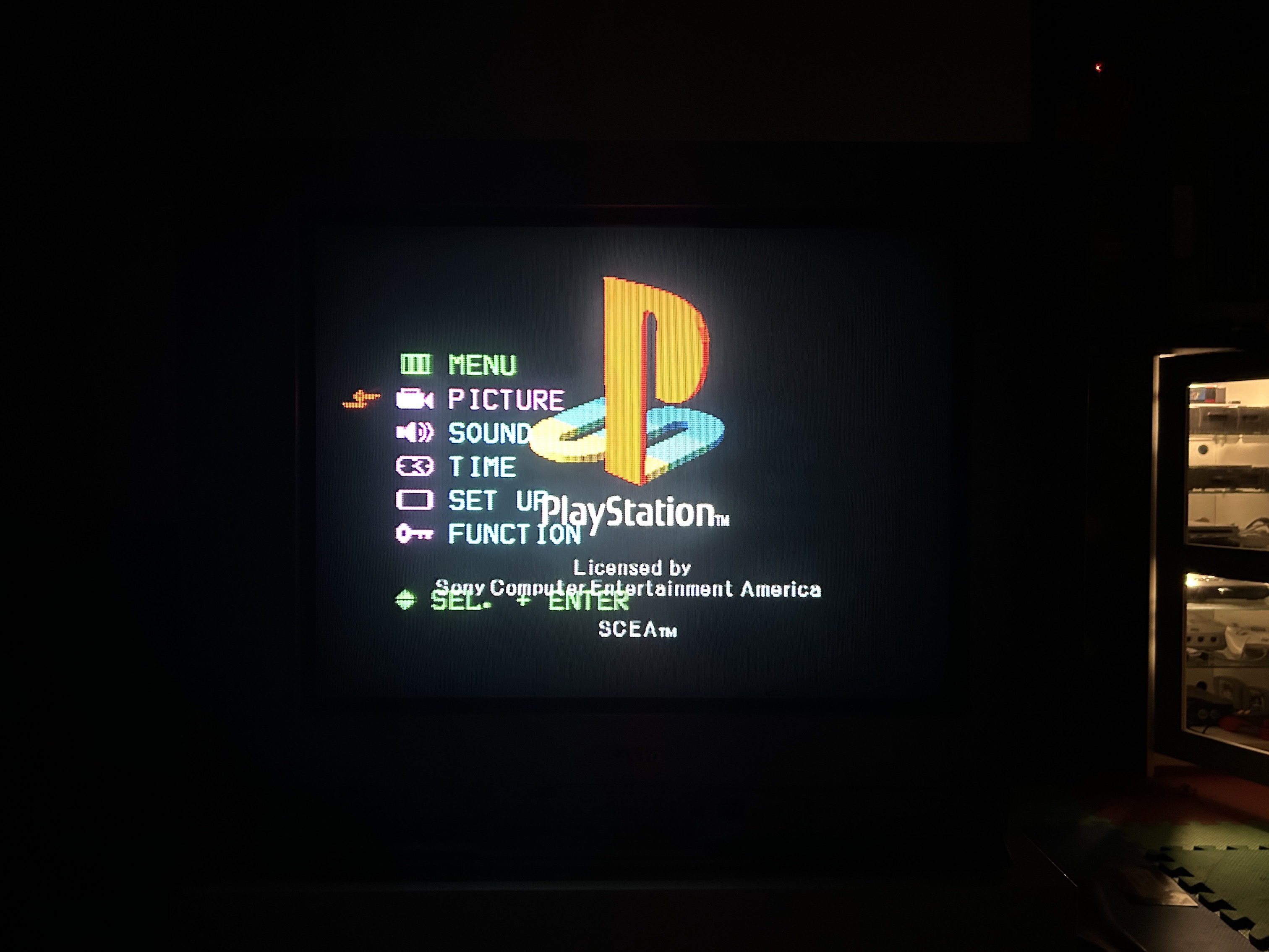
Remote Control for this TV
Despite not having the remote control for this CRT, I was able to use a universal Sony RM-AV3000 remote control with the code 8025 successfully.
Pictures
Reference Photos
See more photos and contributions →
Games
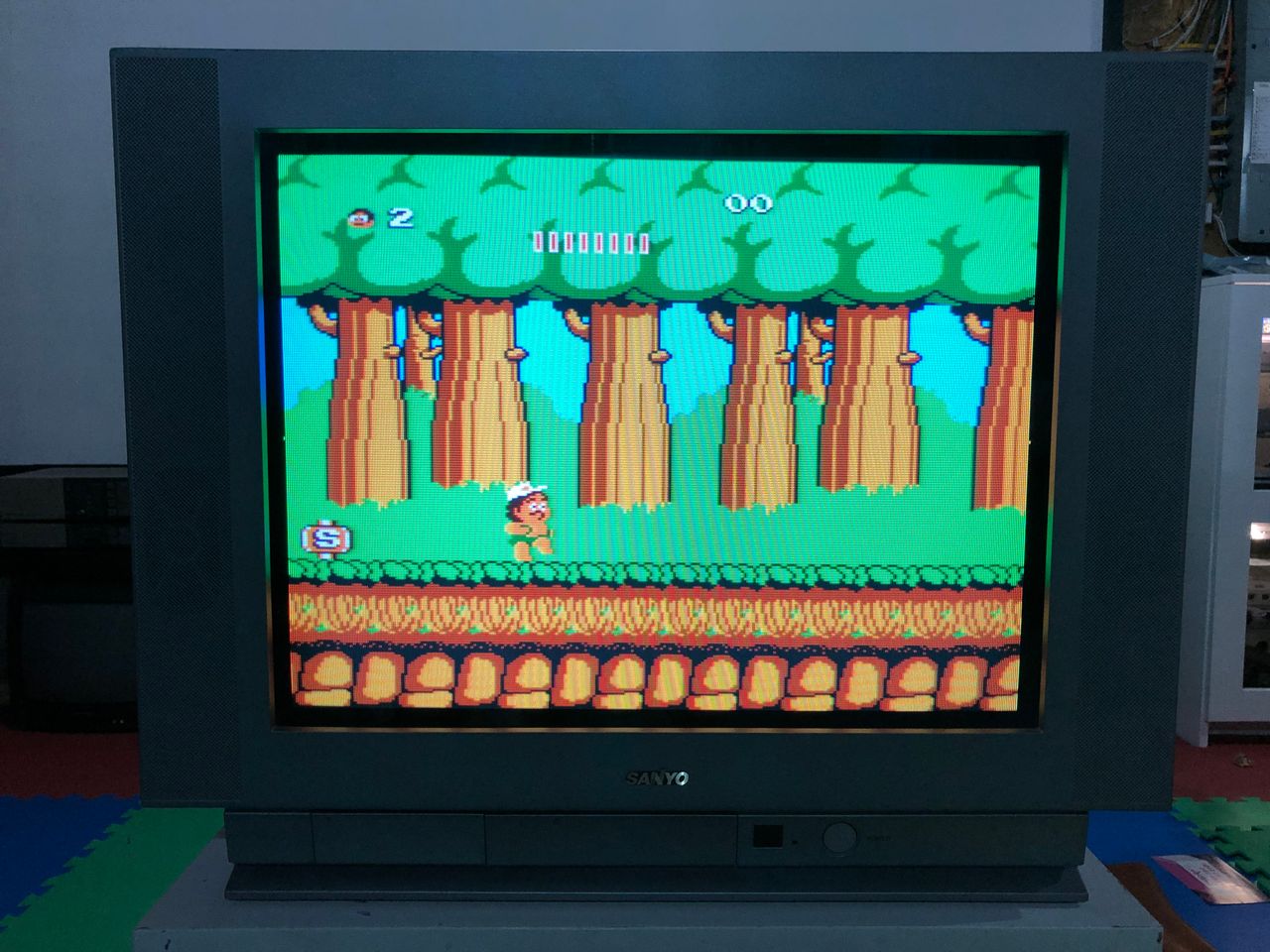
NES - Adventure Island 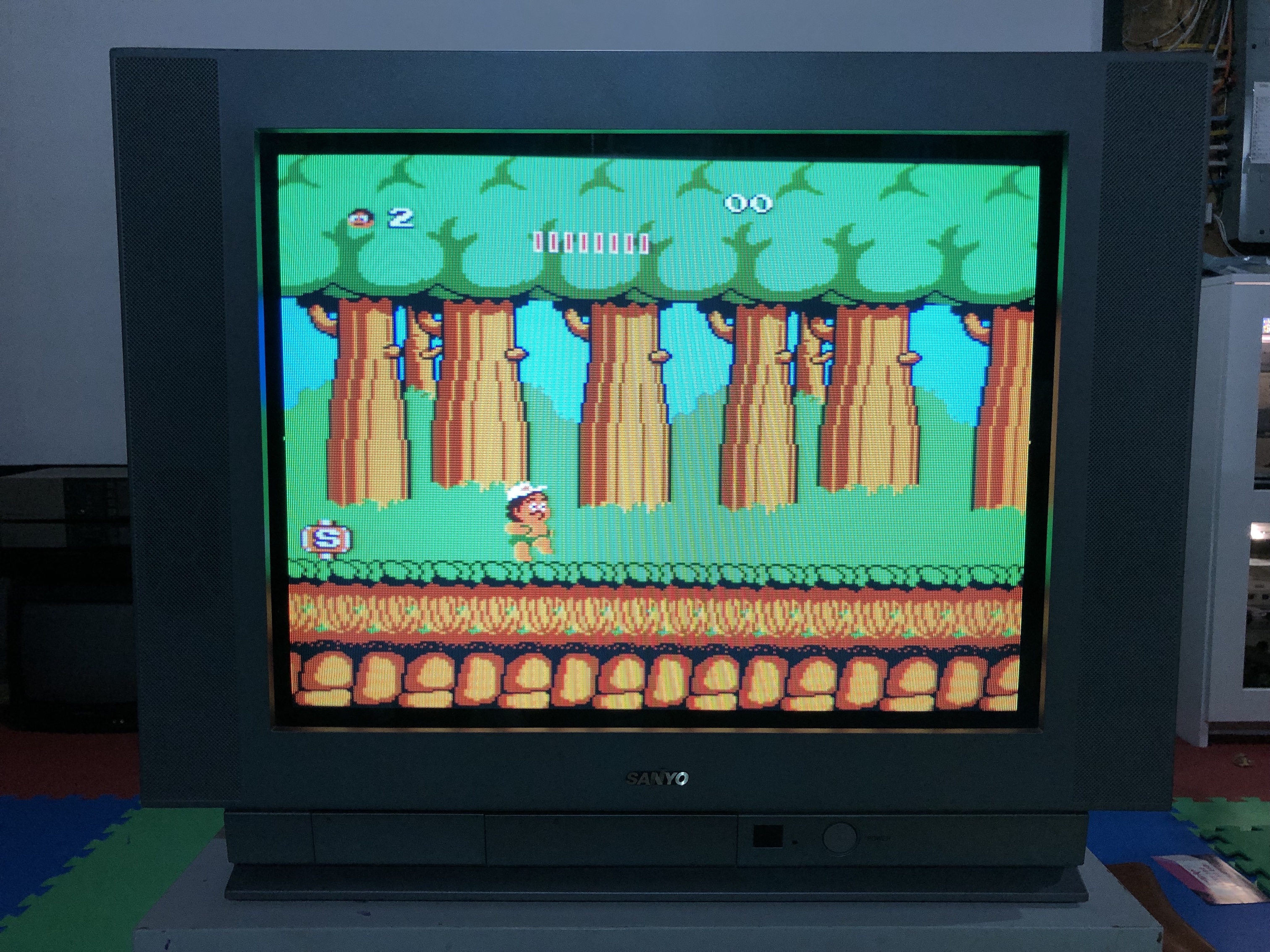
NES - Barbie 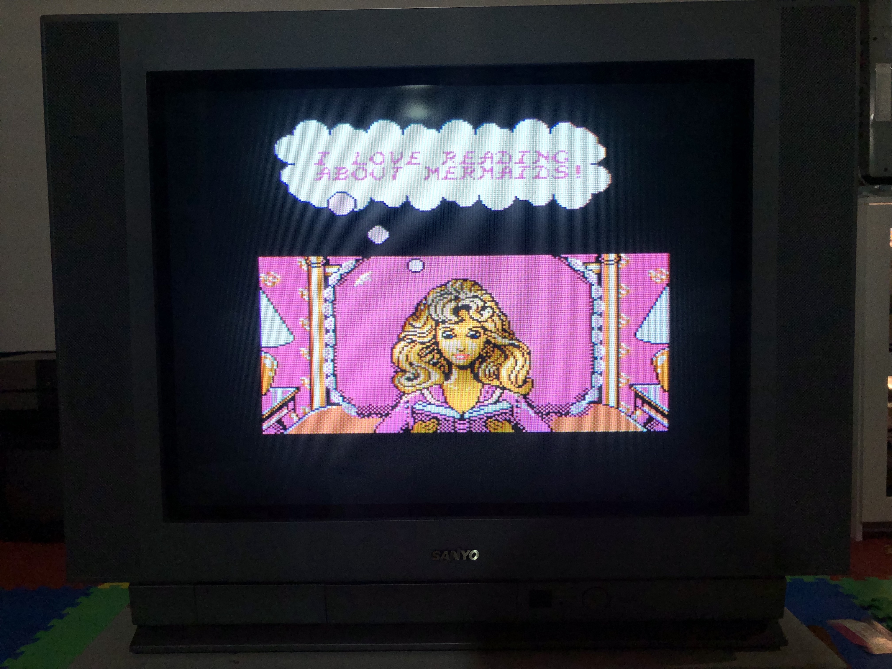
Sega Genesis - Sonic 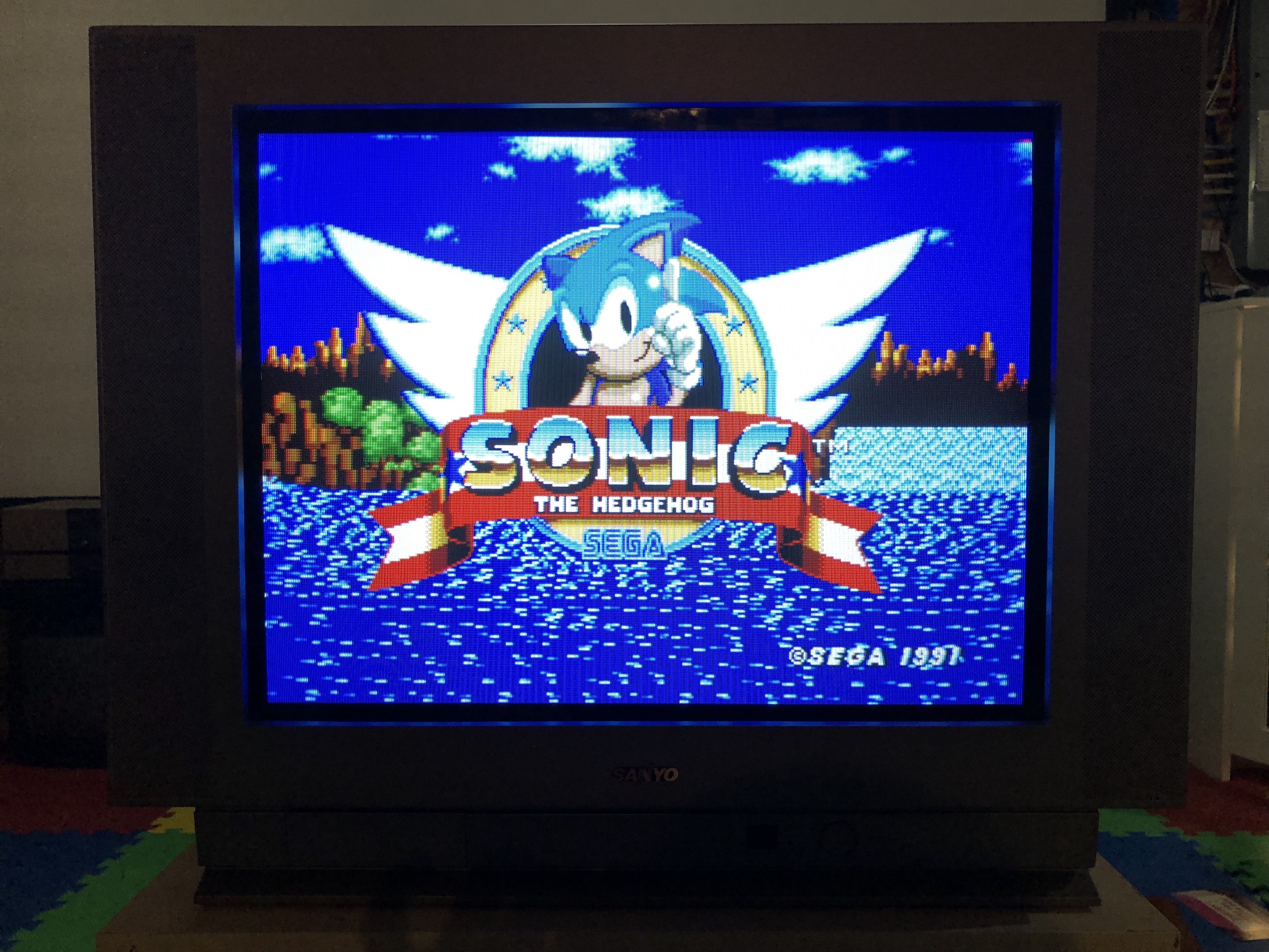
SNES - Megaman X 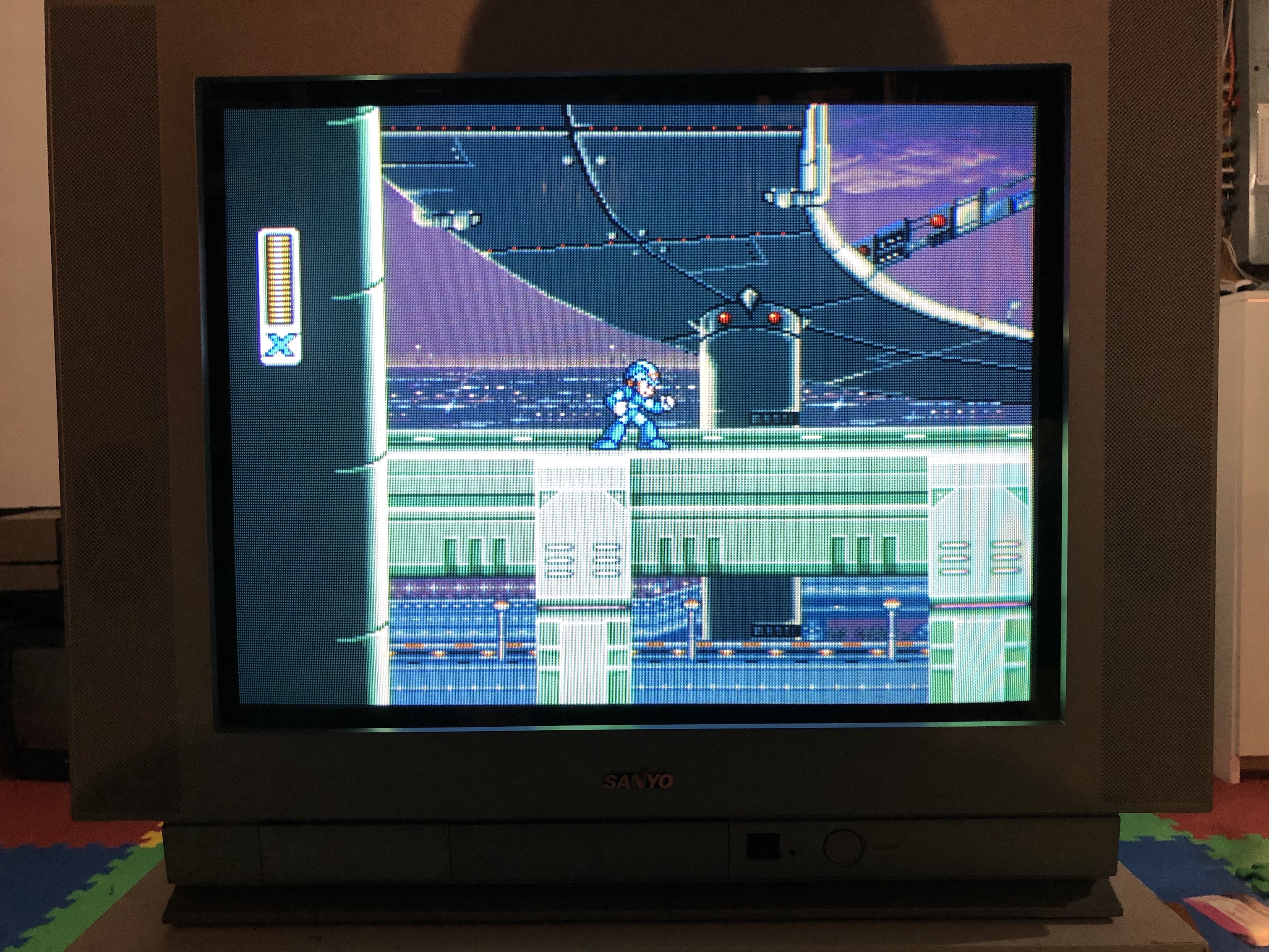
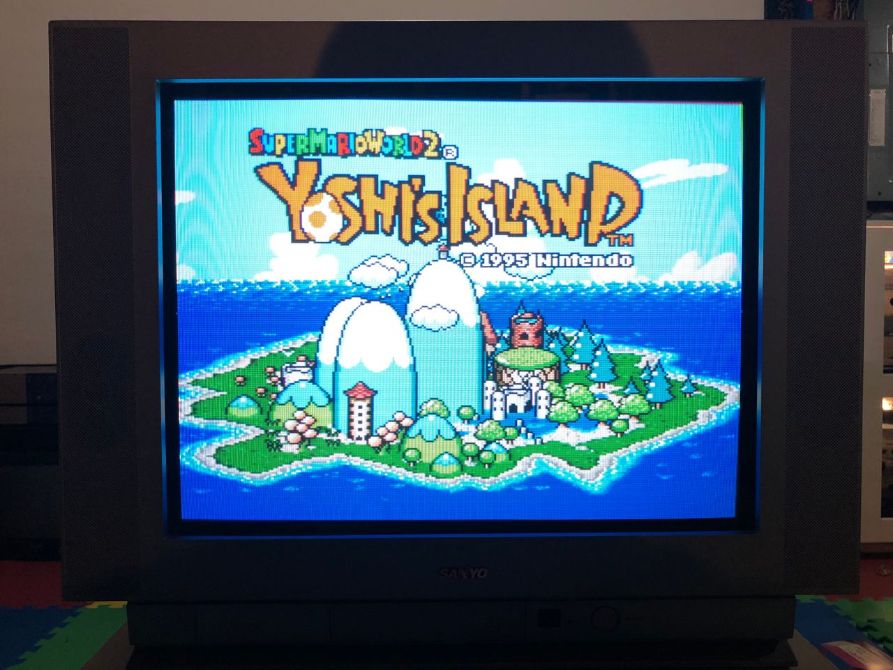
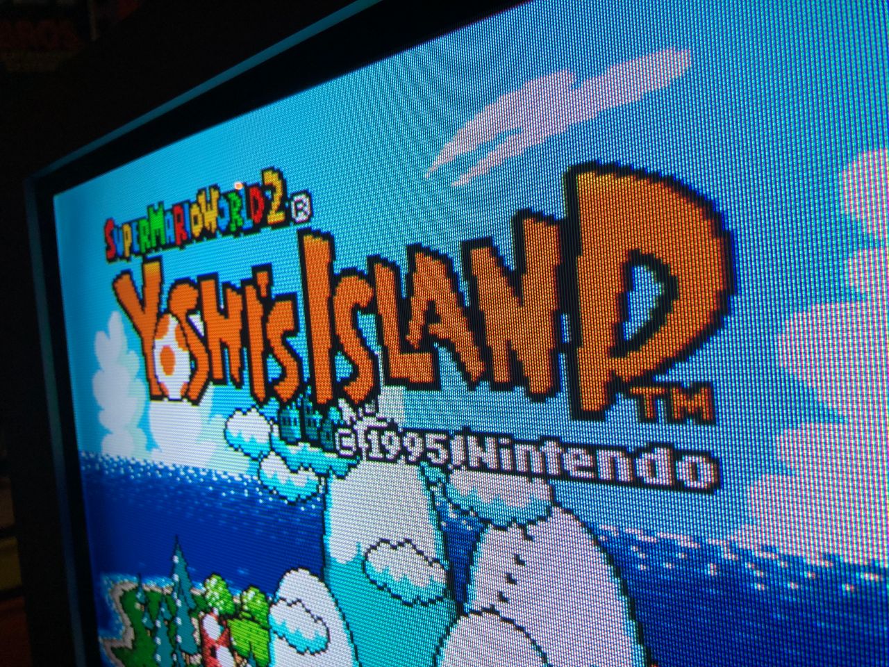
SNES - Yoshi's Island 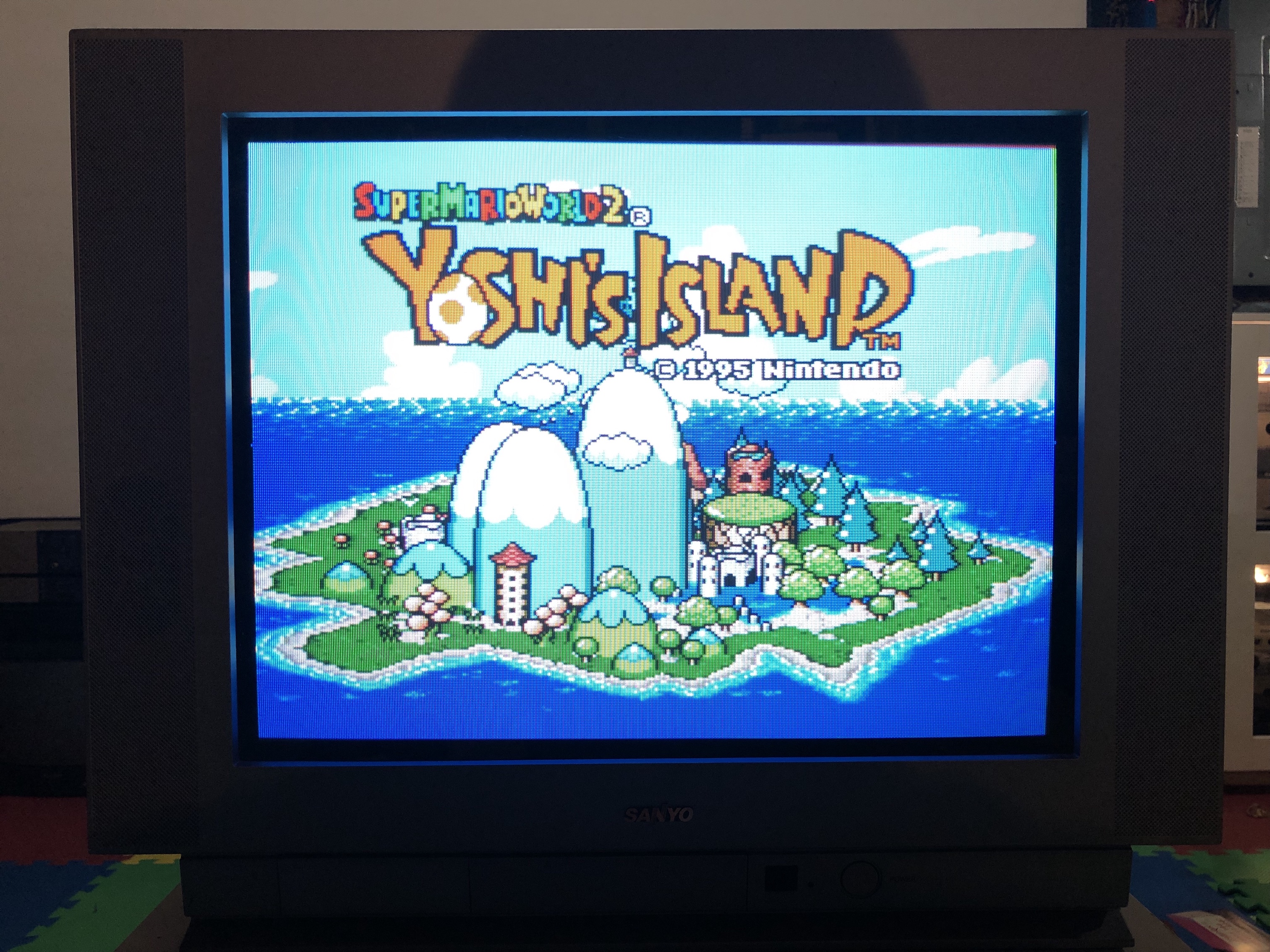
SNES - Yoshi's Island (closeup) 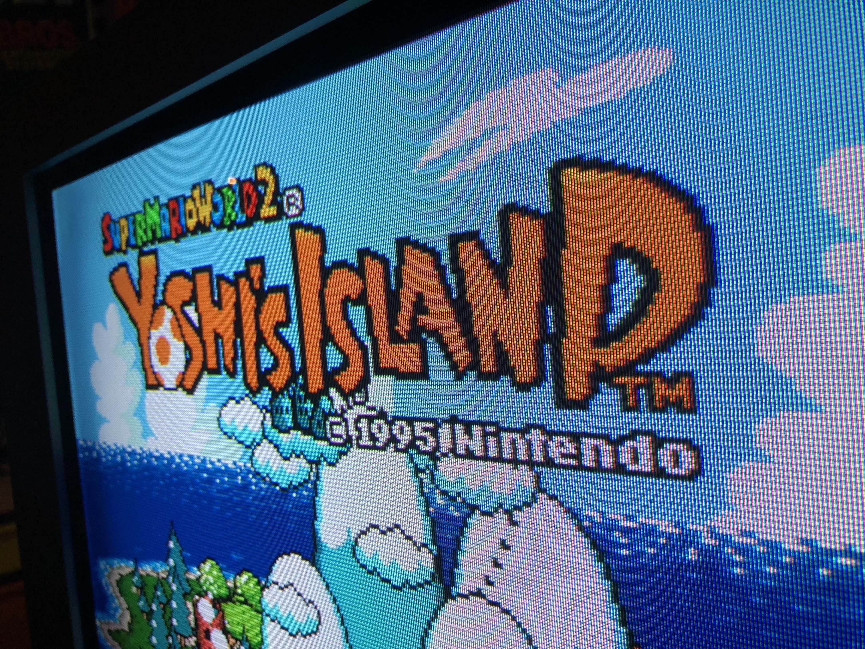
SNES - Metroid (closeup) 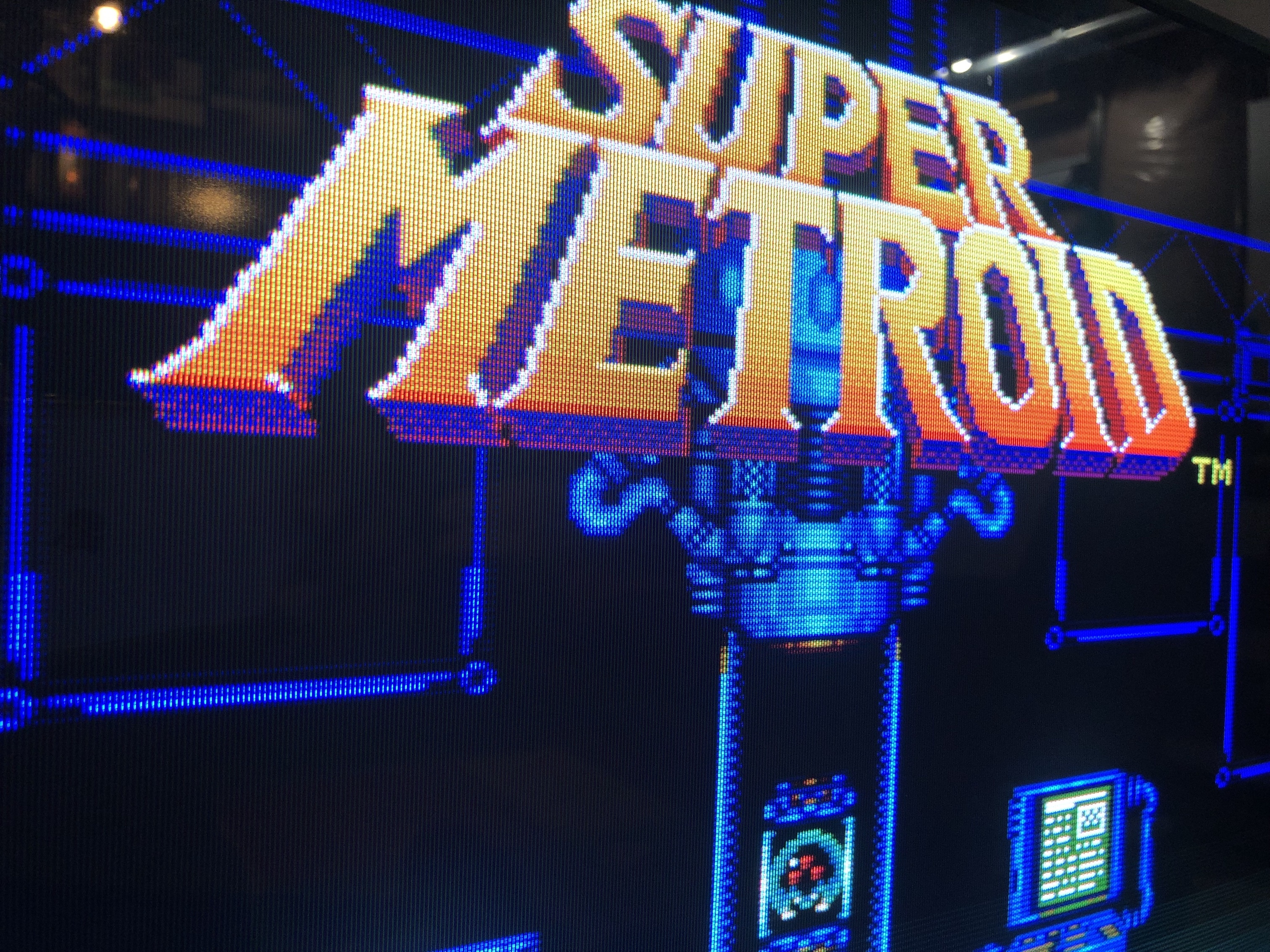
PS1 game booting 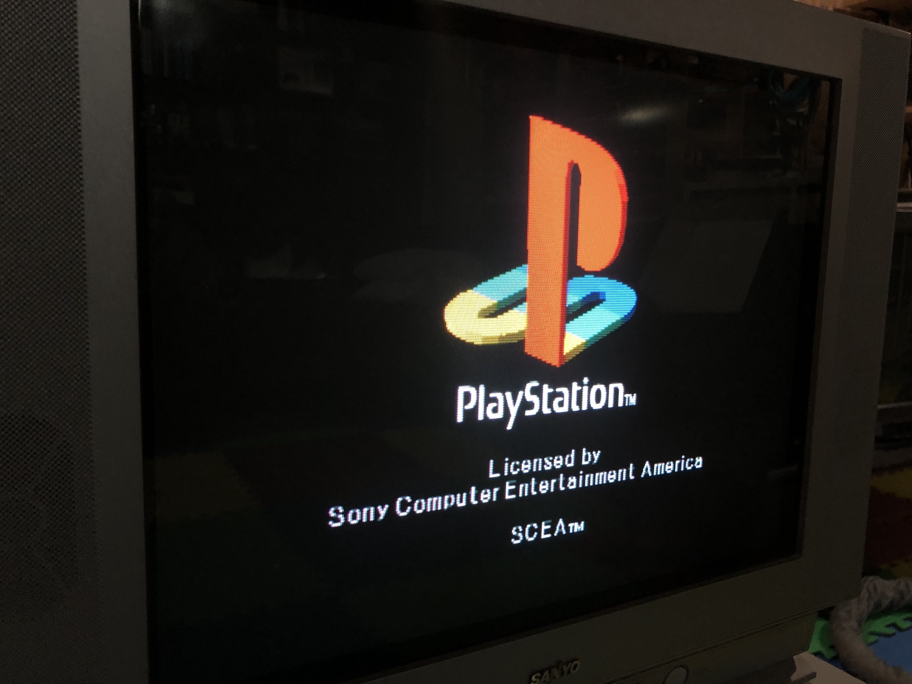
PS1 Sony logo ![]()
Patterns
Pattern - Grid 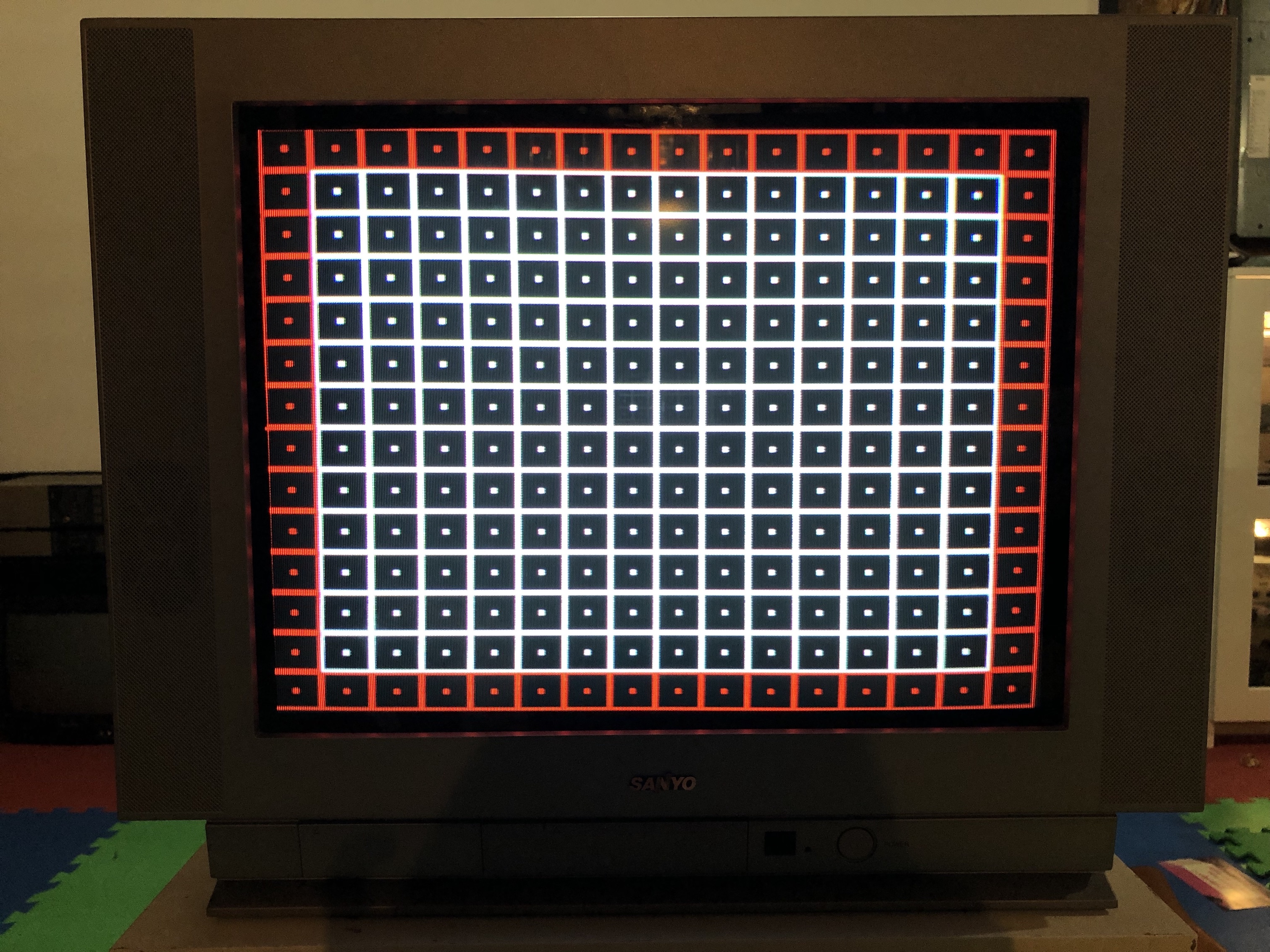
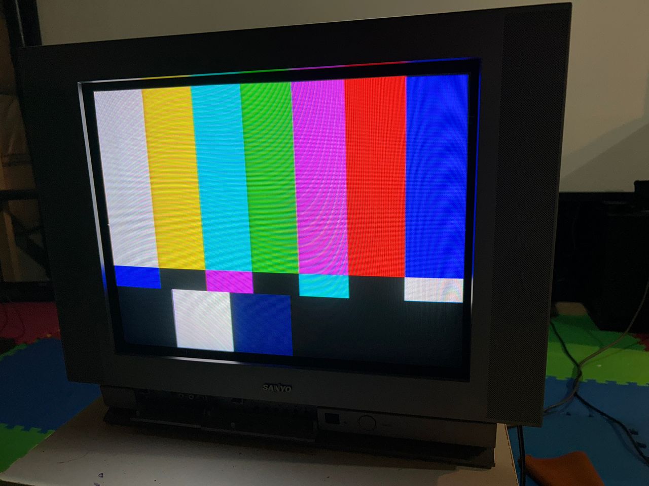
Pattern - SMPTE 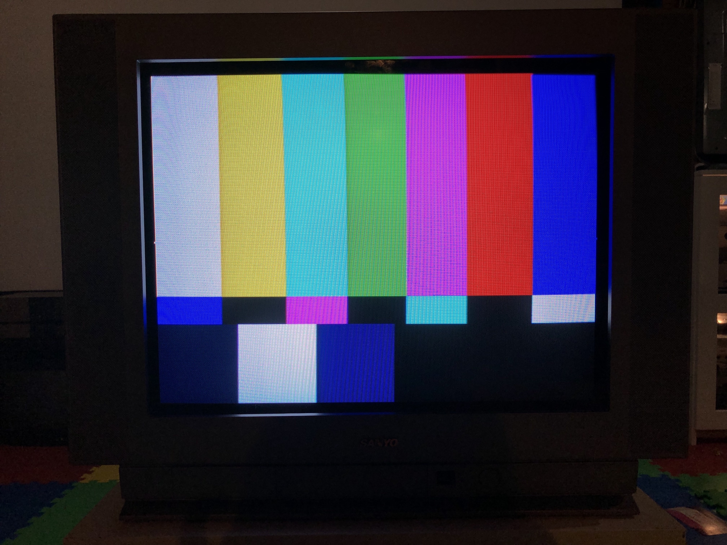
Chassis, Tube and Casing
Tube label 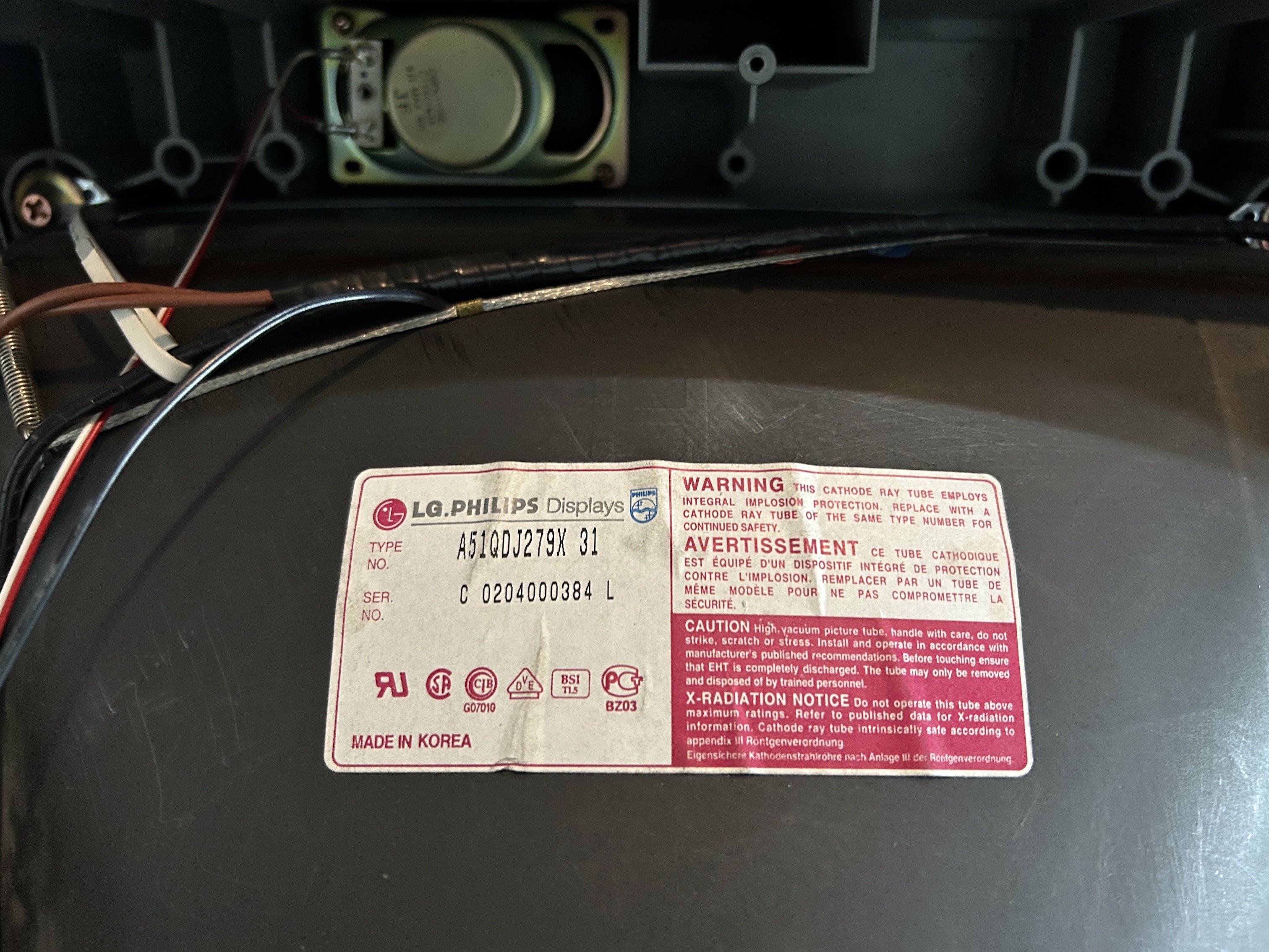
TV back open 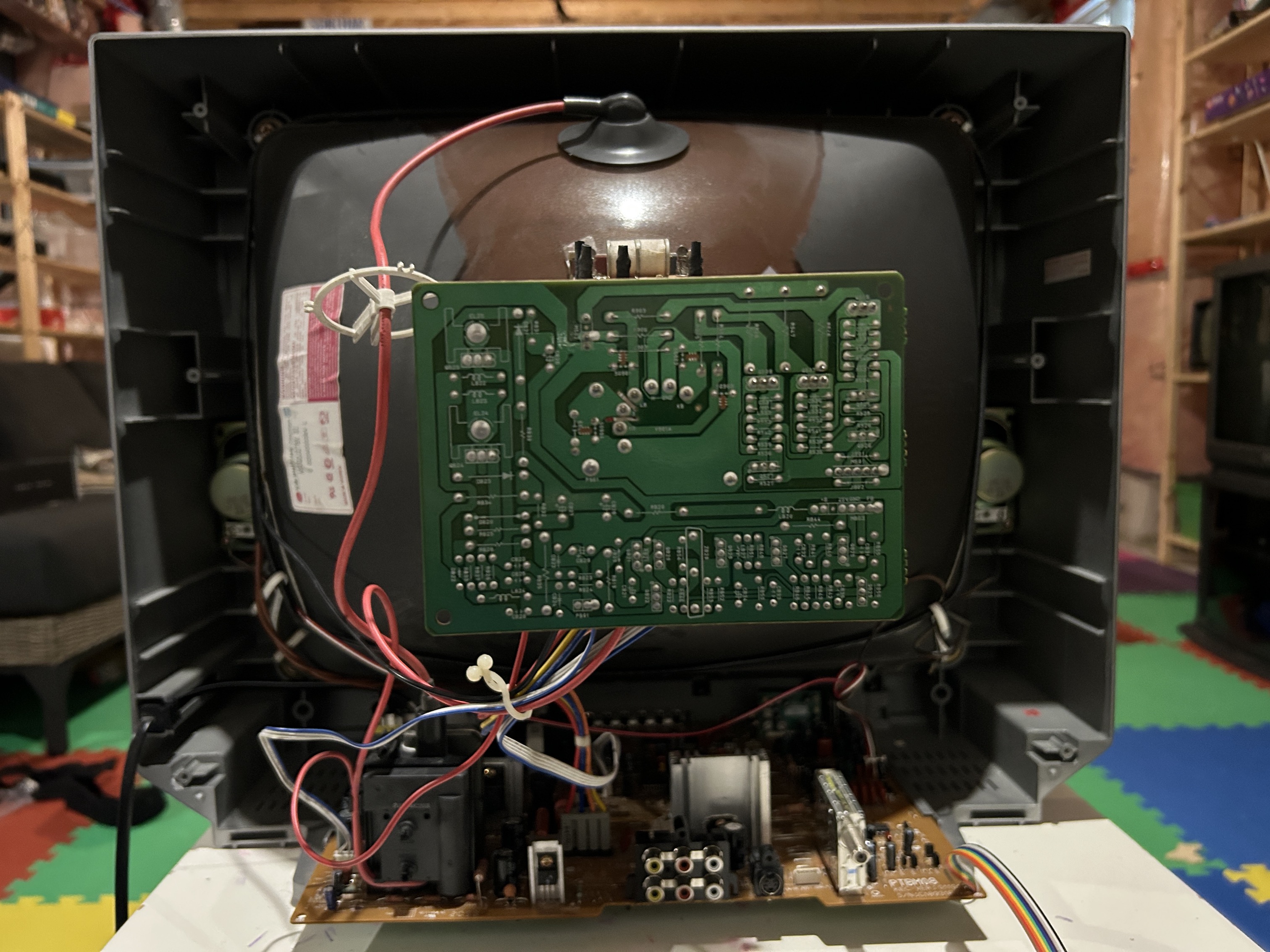
TV neck yoke 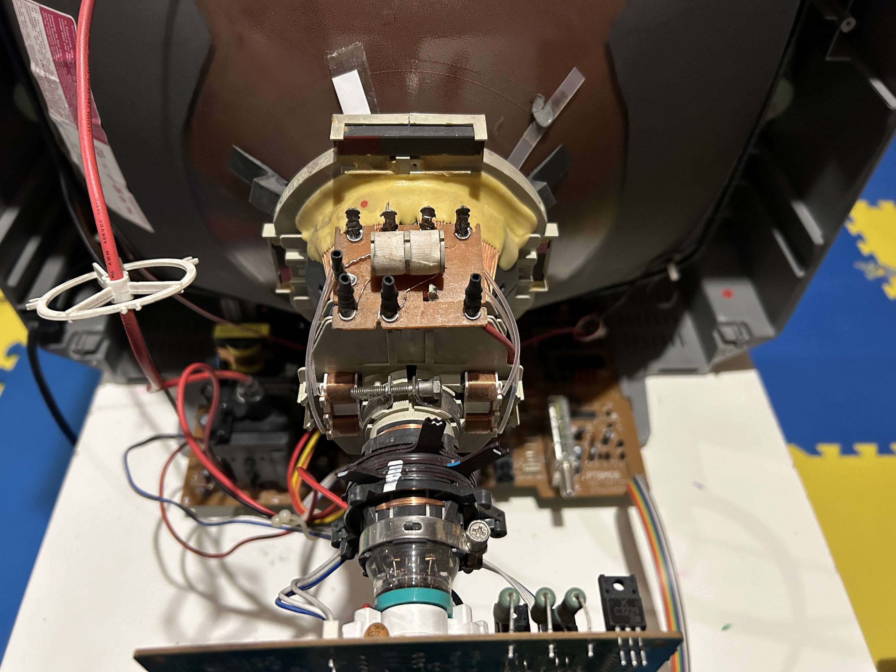
TV front panel