Sony (BG-1S) KV-G14P1
Sony (BG-1S) KV-G14P1 CRT RGB mod
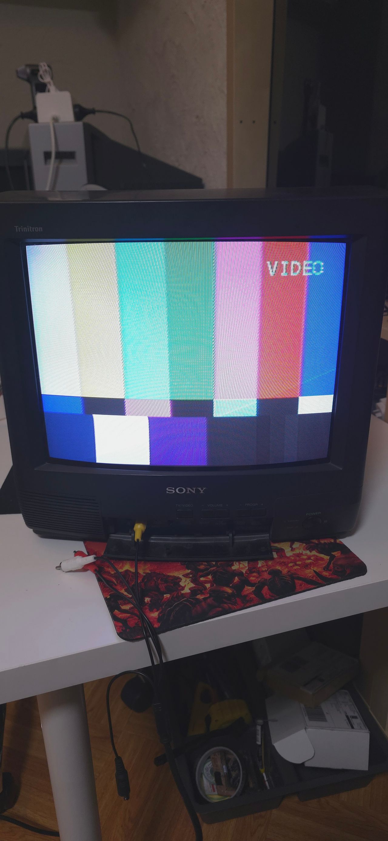
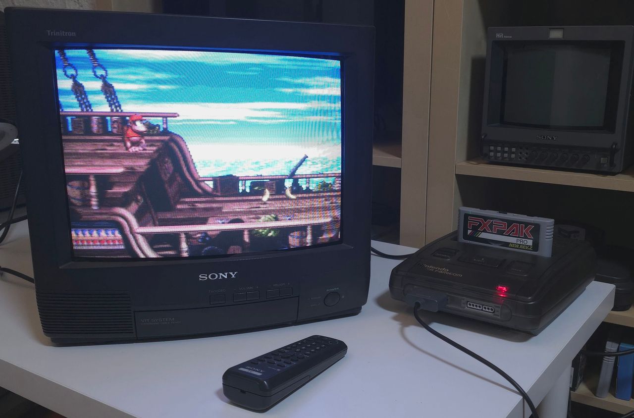
The Sony KV-G14P1 is a 14" Trinitron CRT television. This set is marked as the Thailand model in the service manual.
View full CRT details and more mod examples →
Contributors
Thank you to everyone who contributed to this guide:
- Kevin Smith's Sector — contributor, RGB mod and pictures
CRT safety
Caution
You can die doing this! So read carefully! CRT TV is not a toy. Do not open a CRT TV. If you don't have any prior knowledge about handling high voltage devices, this guide is not for you. CRT TV contains high enough voltage (20,000+ V) and current to be deadly, even when it is turned off.
Plan of attack
Manuals and Datasheets
Specs
- Chassis: BG-1S
- Jungle Chip: Philips TDA8366N3D
- Screen Size: 14"
RGB mux diagram
Prepare the mux diagram. If you are building your own circuit, this diagram should help.
Performing the mod
STEP 1: Remove components
If there are R327, R328, R329 resistors, you should remove them.
If you are going to use the 0.1uF caps on the mux board, you should also remove C319, C320, C321.
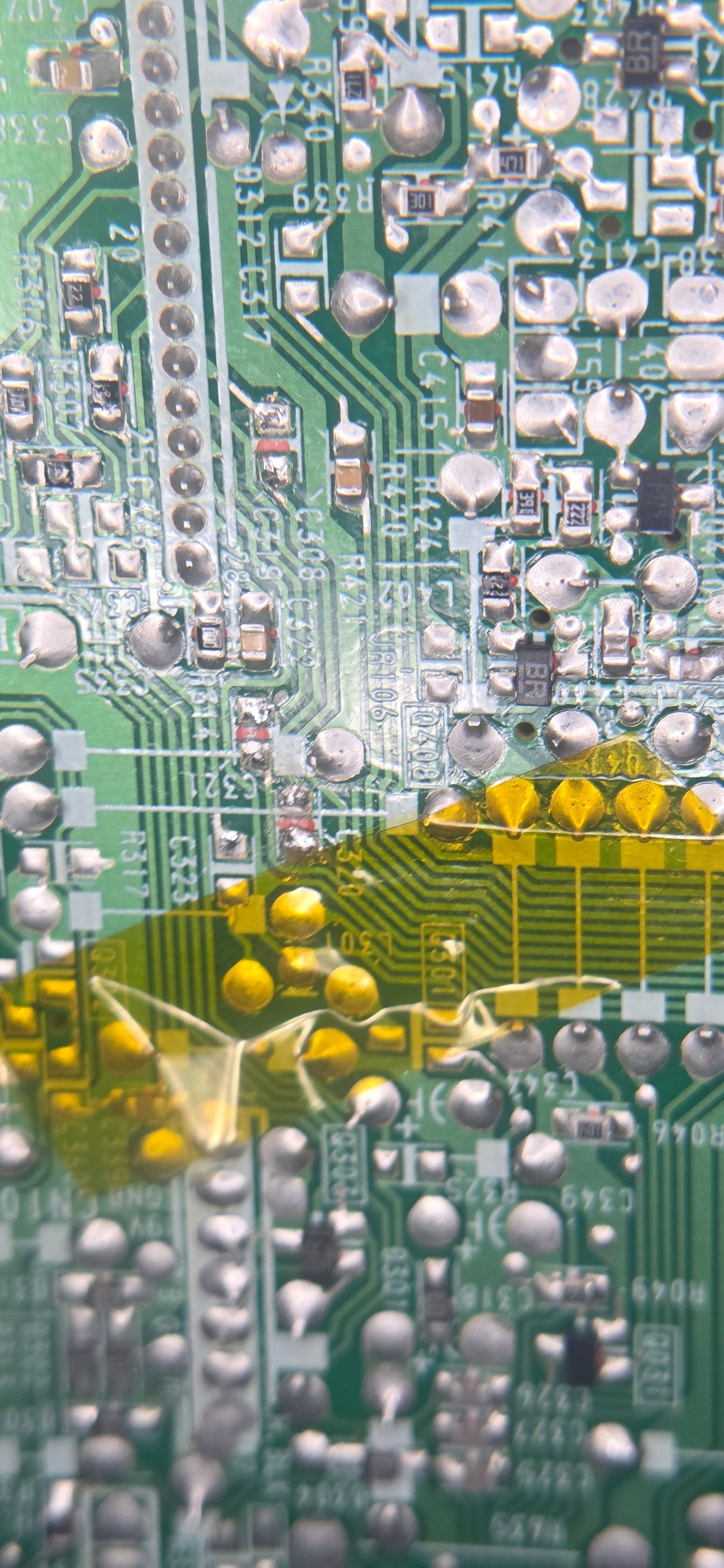
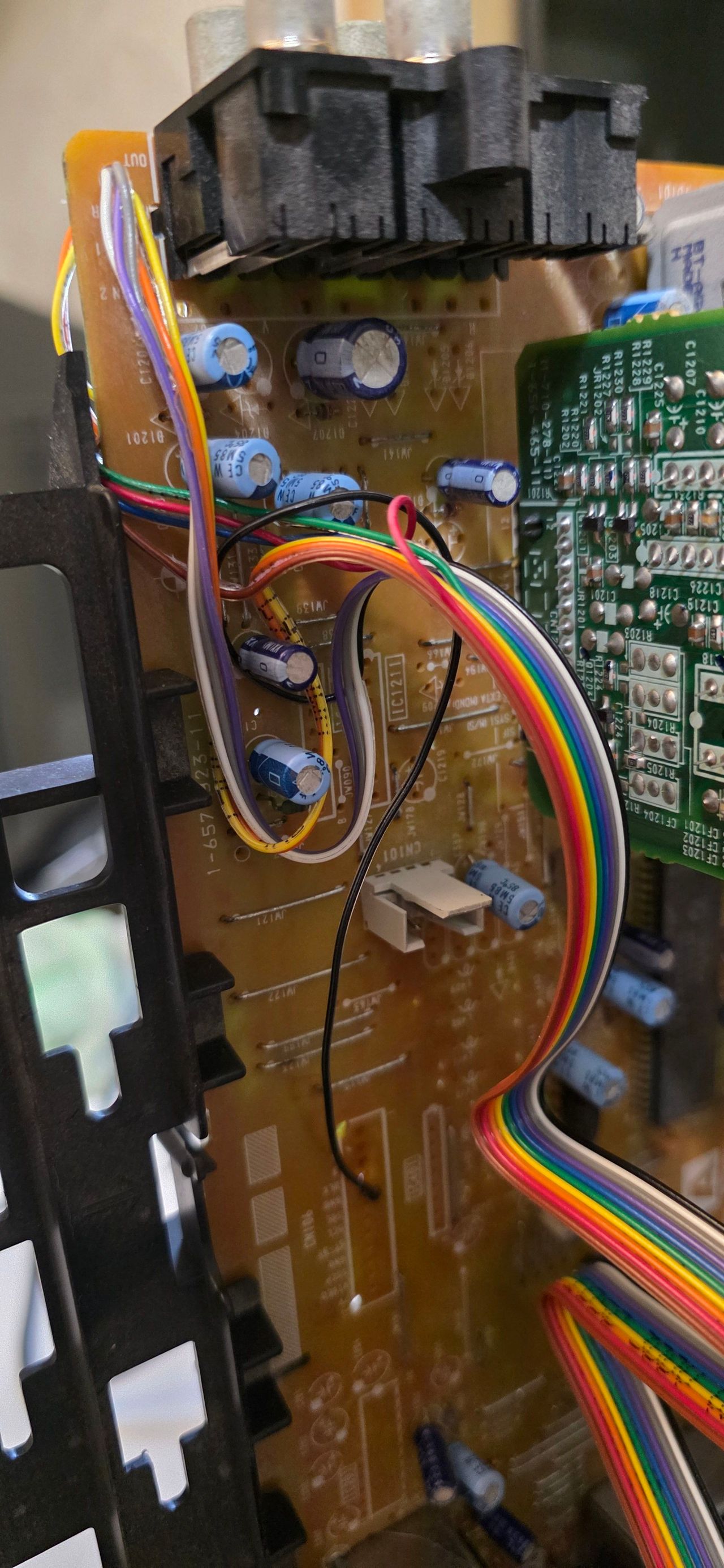
STEP 2: R, G, B and blanking wires
Solder the R, G, B and blanking wires
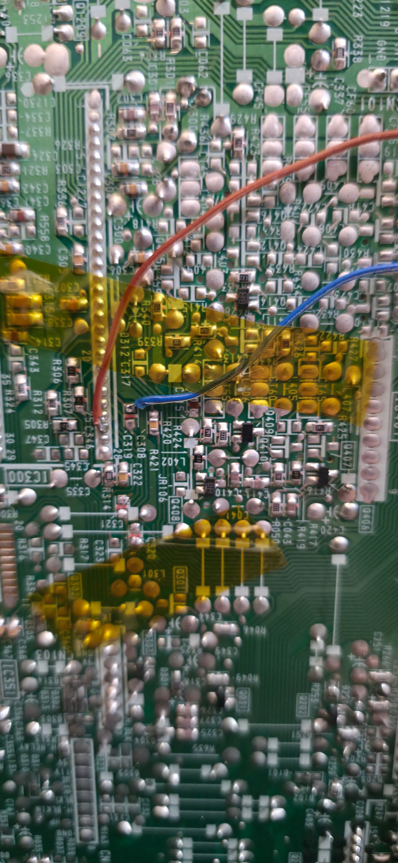
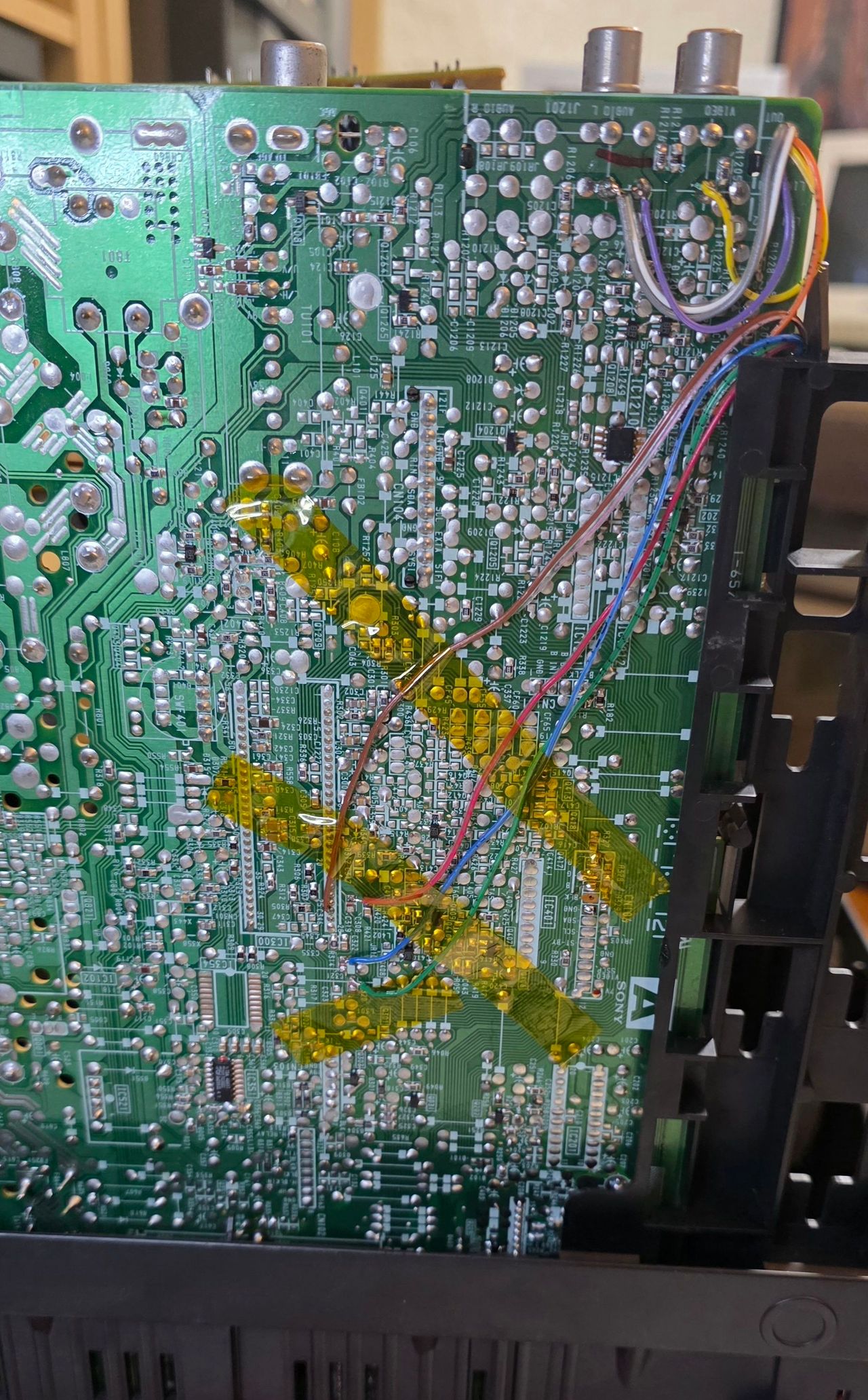
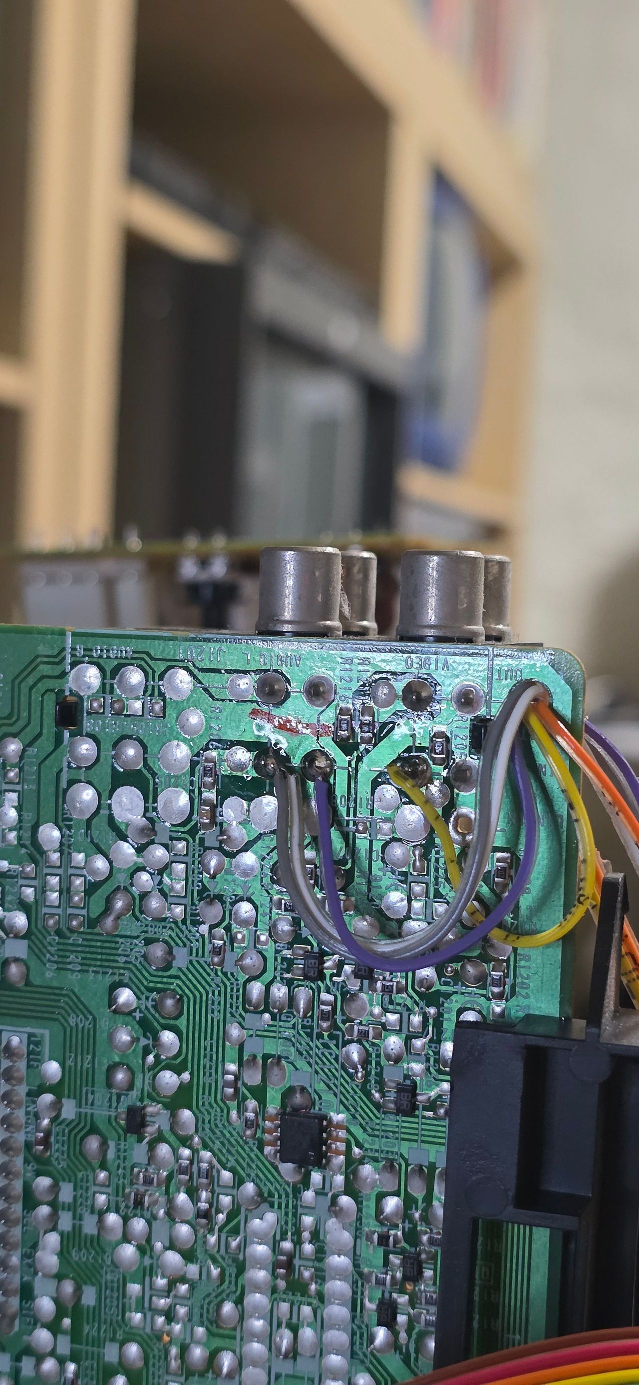
STEP 3: Audio, Sync and Ground wires
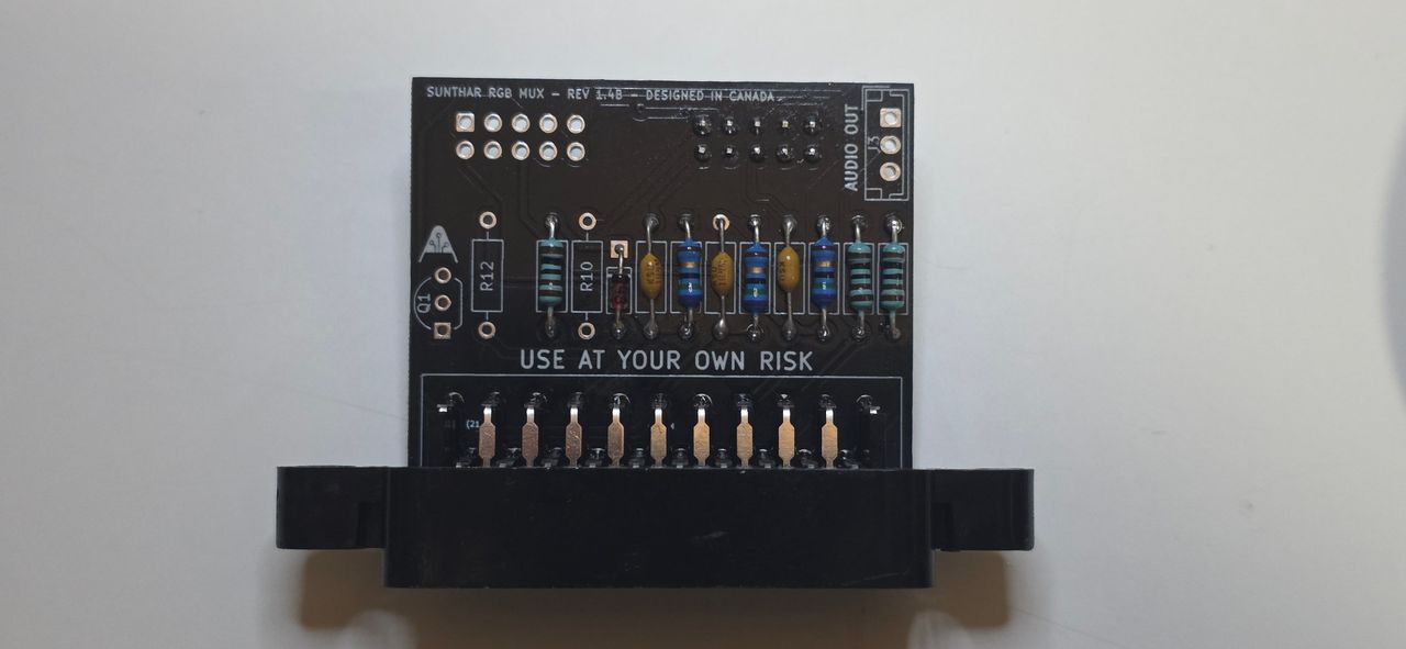
STEP 4: Prepare the mux board
This mod uses the RGB mux board. This is optional, but will make your mod easier and stable. You can also create the circuit presented in the schematics above without the board. Please also checkout the mux calculator to play with your own values.
| On Sony CRT Chassis | KV-G14P1 |
|---|---|
| 0.1μF caps replaced | No |
| Add diodes on chassis RGB lines? | No |
| Add blanking diode on chassis | No |
| Replace blanking resistor on chassis | No |
| RGB mux board | KV-G14P1 |
|---|---|
| Mux board RGB termination (R1, R2, R3) | 75Ω |
| Mux board RGB input capacitors (R4, R5, R6) | 0.1μF |
| Mux board Audio LR (R7, R8) | 1kΩ |
| Mux board blanking diode (R9) | 1N4148 |
| Mux board blanking ground resistor (R10) | open |
| Mux board blanking resistor (R11) | 1kΩ |
Compatible mux boards:
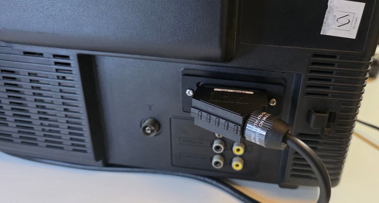
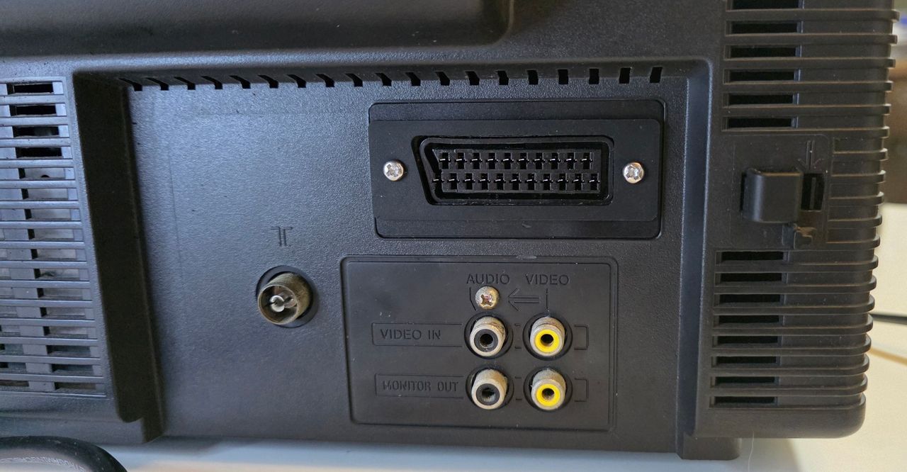
STEP 5: Mount SCART port
Pictures
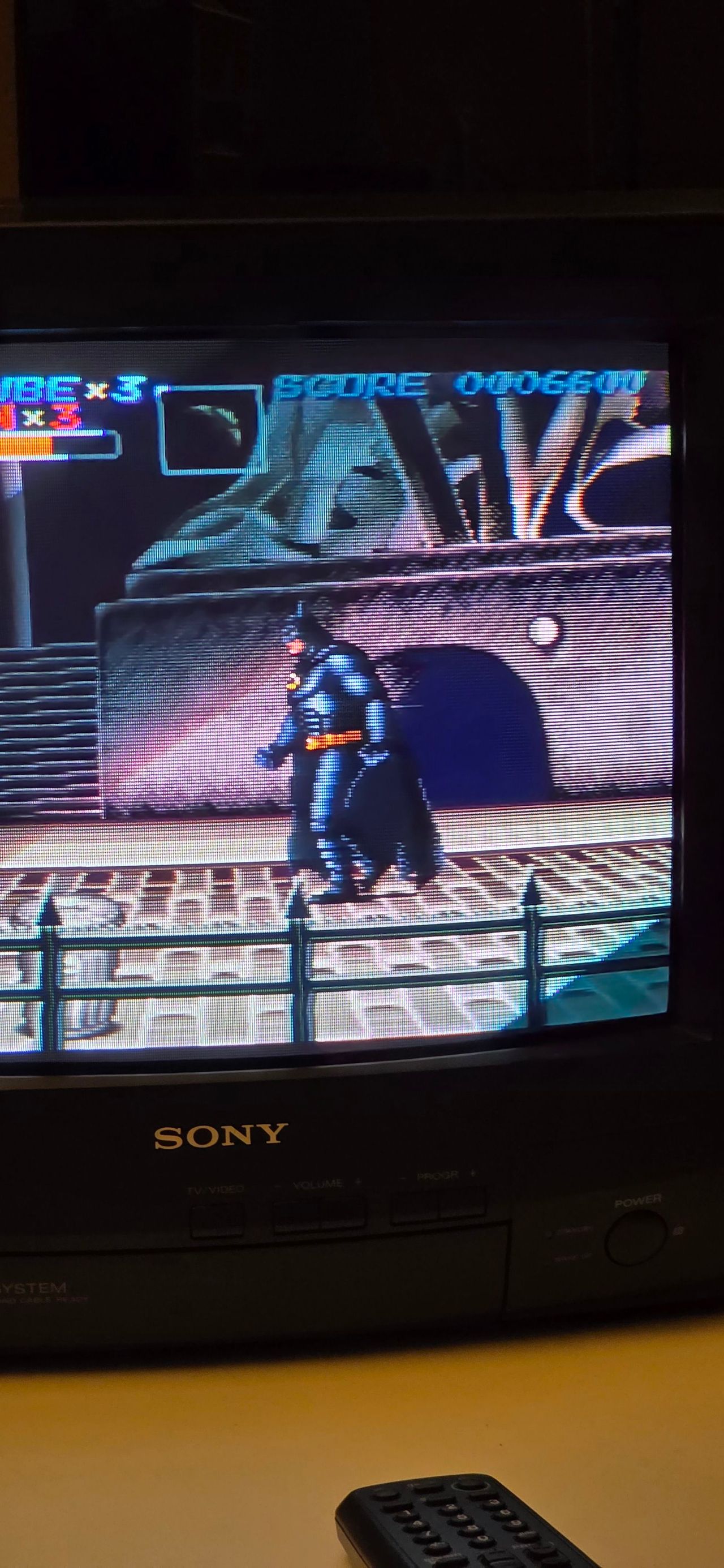
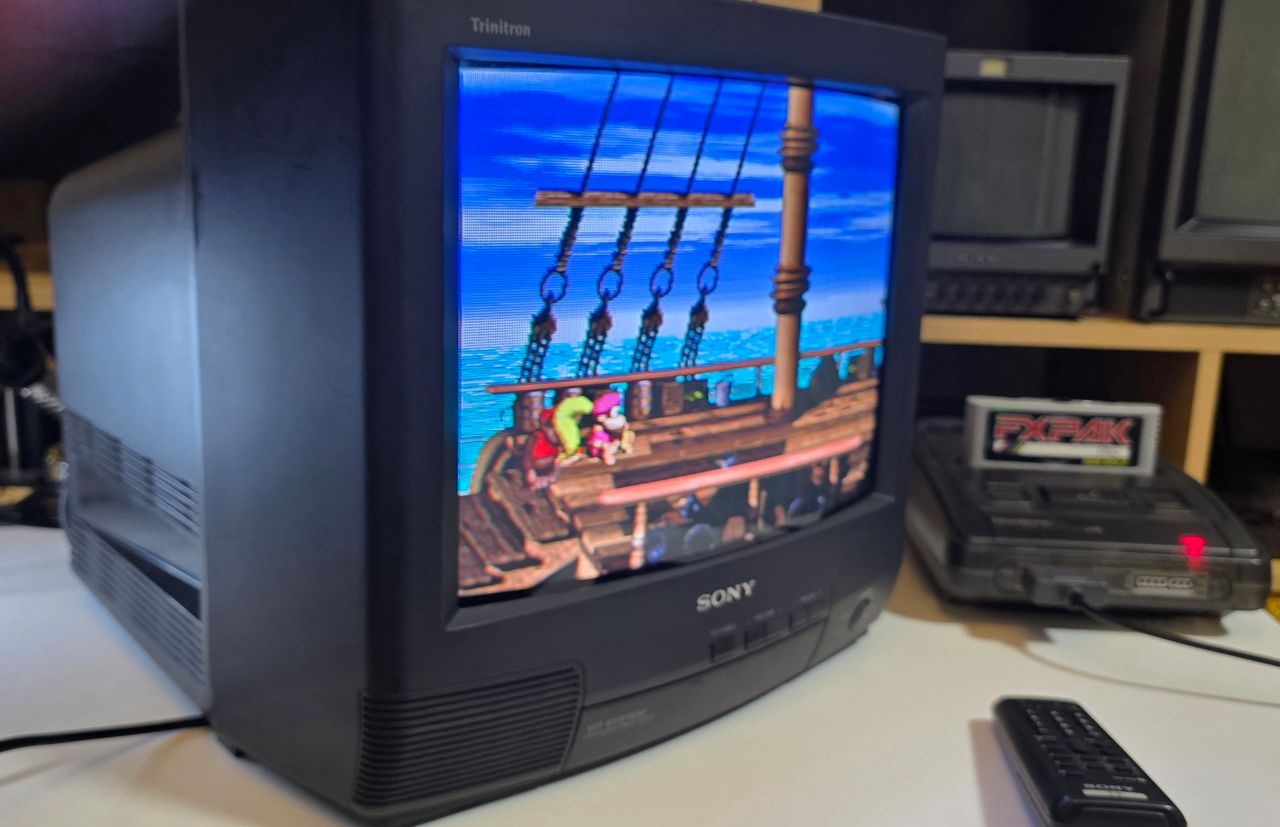
Mod Photos
RGB modification showcase of a Sony KV-G14P1 CRT.