Sony (AA-1) KV-27V10
Sony (AA-1) KV-27V10 CRT RGB mod
The Sony KV-27V10 is a highly regarded 27" curved Trinitron CRT television produced in the mid-90s, known for its excellent picture quality, pronounced scanlines, and superior sound. It features S-Video and composite inputs. The "V" in the model number signifies "Very (good) Stereo."
For example, KV-27S10 has mid-range sound.
- M (Mono): Entry-level models with a single speaker and basic inputs
- S (Stereo): Mid-range models featuring two speakers and standard stereo sound
- V (Very Stereo): Higher-end models that offered superior audio wattage
View full CRT details and more mod examples →
Contributors
Thank you to everyone who contributed to this guide:
No contributors listed yet.
CRT safety
Caution
You can die doing this! So read carefully! CRT TV is not a toy. Do not open a CRT TV. If you don't have any prior knowledge about handling high voltage devices, this guide is not for you. CRT TV contains high enough voltage (20,000+ V) and current to be deadly, even when it is turned off.
Plan of attack
Manuals and Datasheets
Specs
- Manufactured: USA (1994)
- Chassis: AA-1
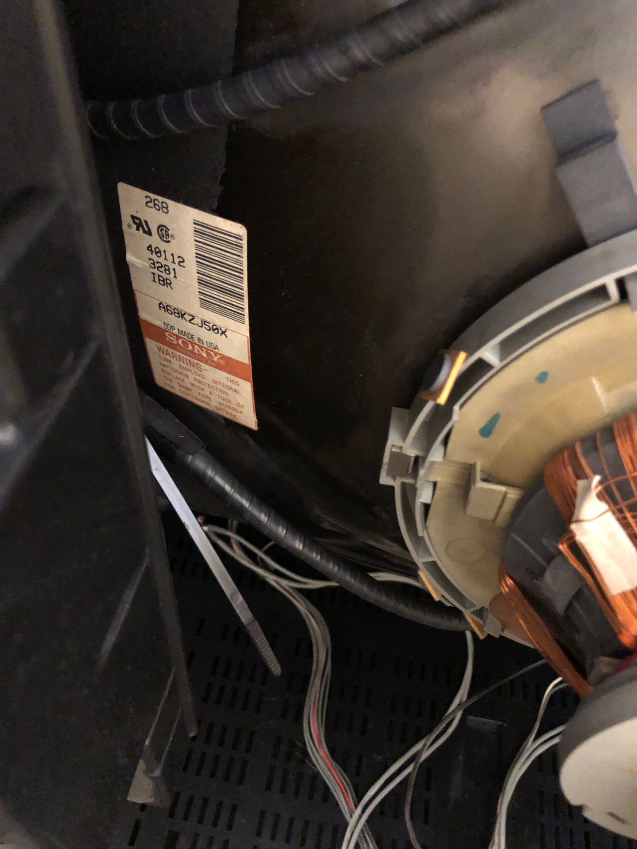
- Tube: Sony Trinitron A68KZJ50X
- Jungle Chip: Sony CXA1465AS
- Power: 165 W
RGB mux diagram
Prepare the mux diagram. If you are building your own circuit, this diagram should help.
Schematics
Really simple RGB mod is possible on this chassis. We will be disabling Closed Caption Decoder (CCD) and leveraging the analog RGB inputs used to feed our external RGB signal.
Let's review the block diagram and schematics first.
Chroma CXA1465AS - Block Diagram 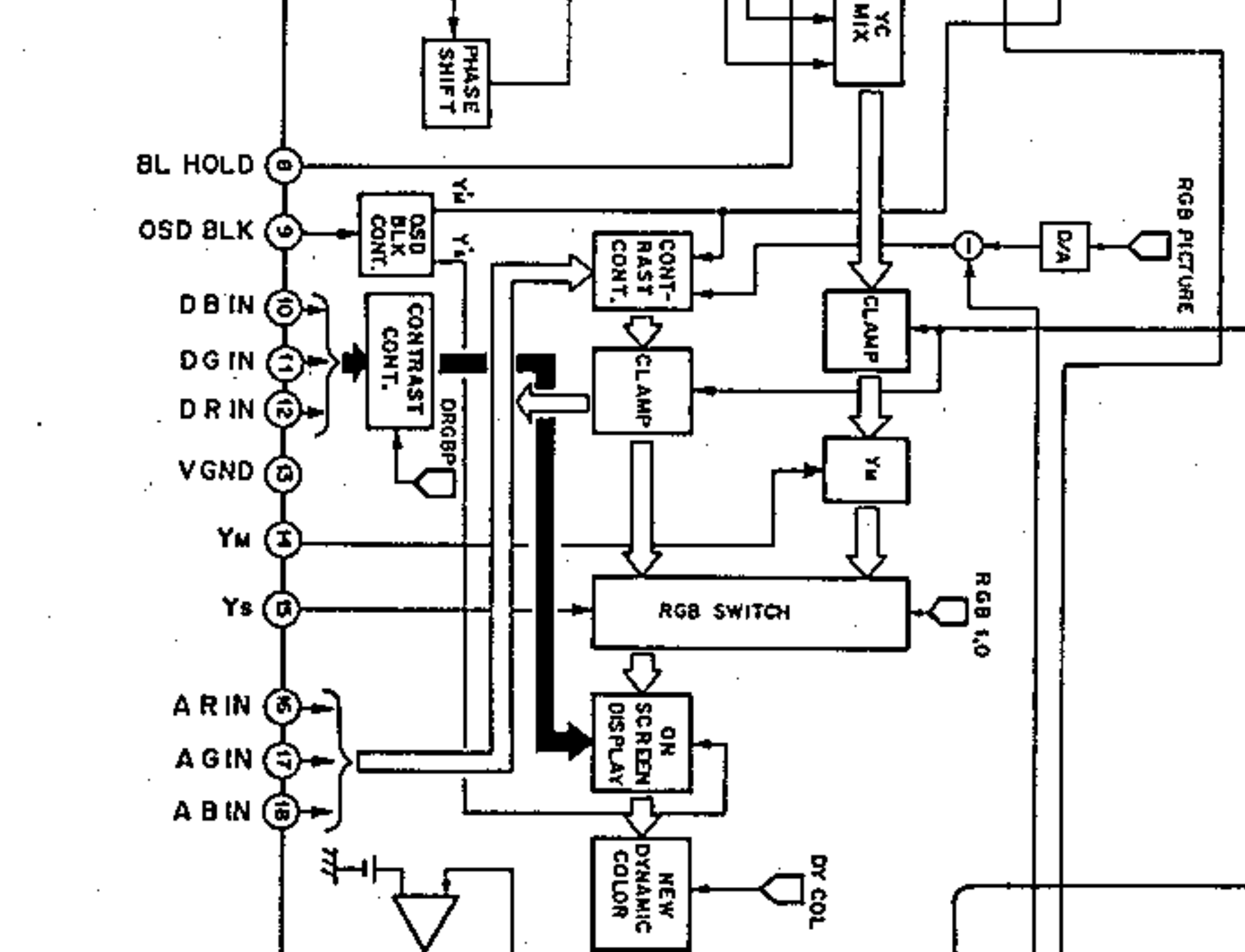
If you look at the block diagram, analog R, G, B inputs at pins 16, 17, 18 are what we are going to be harnessing.
Chroma CXA1465AS - Schematics 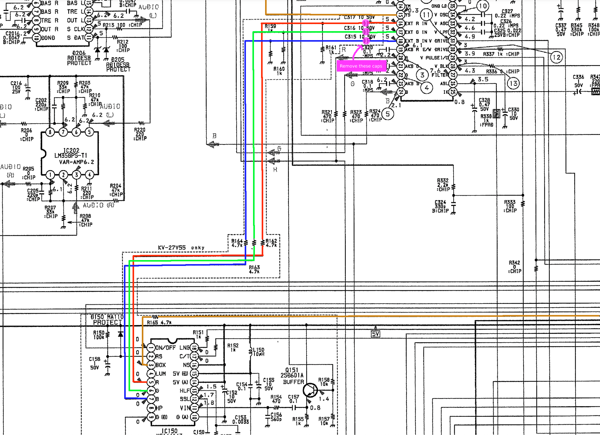
The above schematics shows the R, G, B, Blanking signal going from the CCD chip to the CXA1465AS chip. Pink circle shows the caps C315, C316 and C317 that we will be removing.
Performing the mod
This mod leverages the CCD input. You will disconnect the CCD and inject analog RGB there.
Remove capacitors C315, C316, C317 on the M board and inject R, G, B to the positive terminals. Isolate blanking by removing R165 and inject blanking there.
You only need to touch two boards on this CRT to do the RGB mod. (1) U(A) board. (2) M board.
No need to remove anything else or mess with the anode cup etc. for the RGB mod. This makes it AA-1 one of the simplest chassis to RGB mod. However, disassembling and getting to these boards can be somewhat of a pain.
STEP 1: Attach RGB wires
At the time of this writing there were no successful AA-1 RGB mods that were posted. Instead of removing the CCD chip or messing around with the SMD resistors, let's remove the 10uF 50V electrolytic caps. Removing the electrolytic caps will disconnect the CCD RGB input to the chroma chip. We will then inject our RGB signals directly through 3x 0.1uF ceramic caps to the chroma chip. We will be attaching the R, G, B wires to the +ve terminals of C317, C316 and C315 respectively.
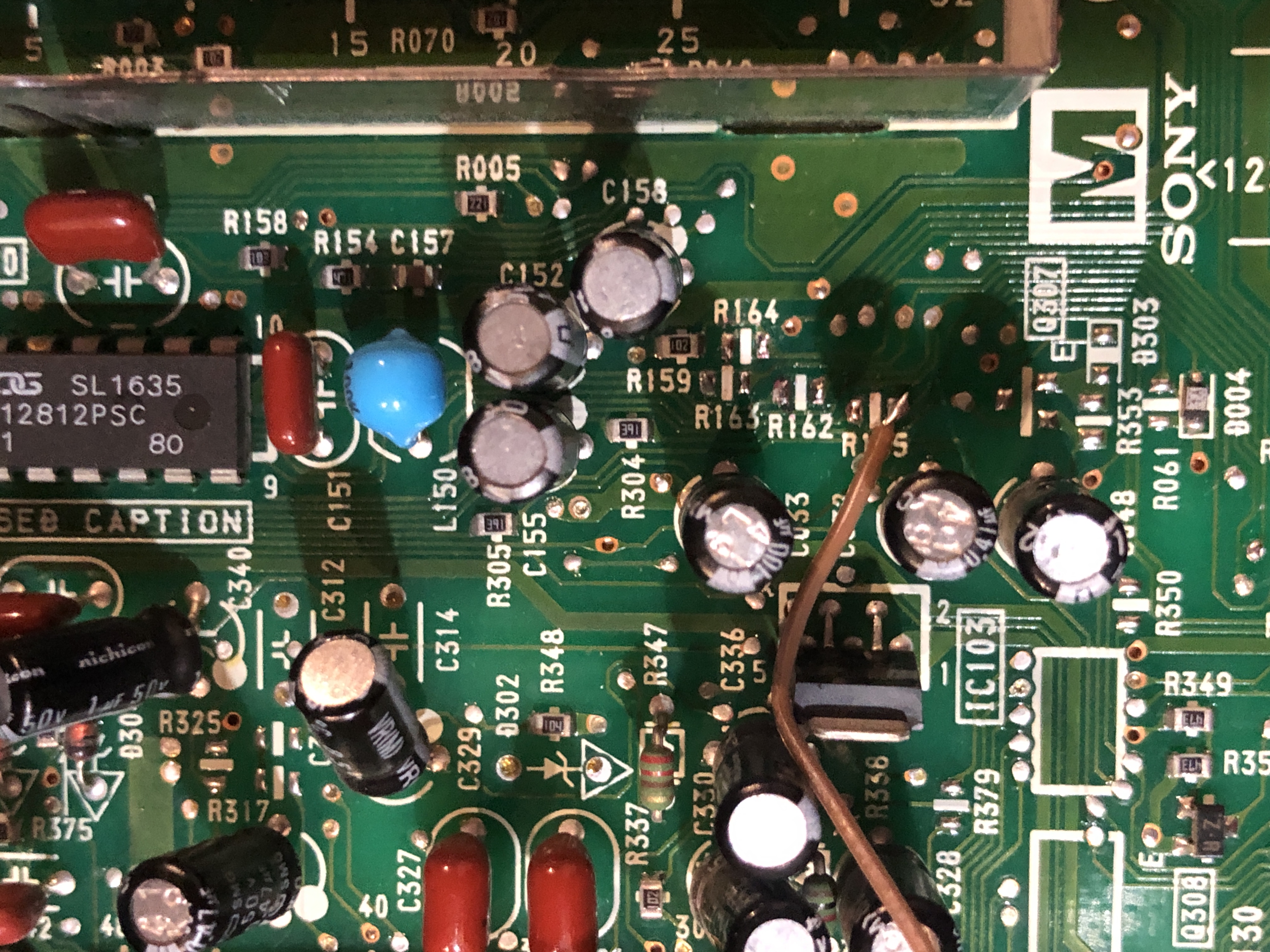
Left: Caps to remove on M board, Right: Attach RGB wires to the +ve vias 
Removed caps. Oddly satisfying to see them removed.! 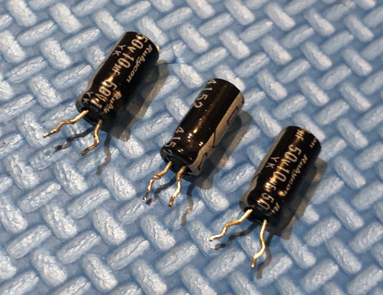
STEP 2: Attach blanking wire
Important! Remove the R165 SMD resistor. This should effectively disconnect the blanking signal going to the chroma chip. The value of this resistor should be 4.7k.
Connect blanking wire, just before the SMD diode D004. Attaching the blanking wire to the R165 pad away from the CCD chip should also work. This is what was done in this mod.
You can also attach the wire to the diode leg. Make sure to pay attention to where you solder the external 5V blanking wire (brown wire). Making a mistake here can potentially fry components on the M board.
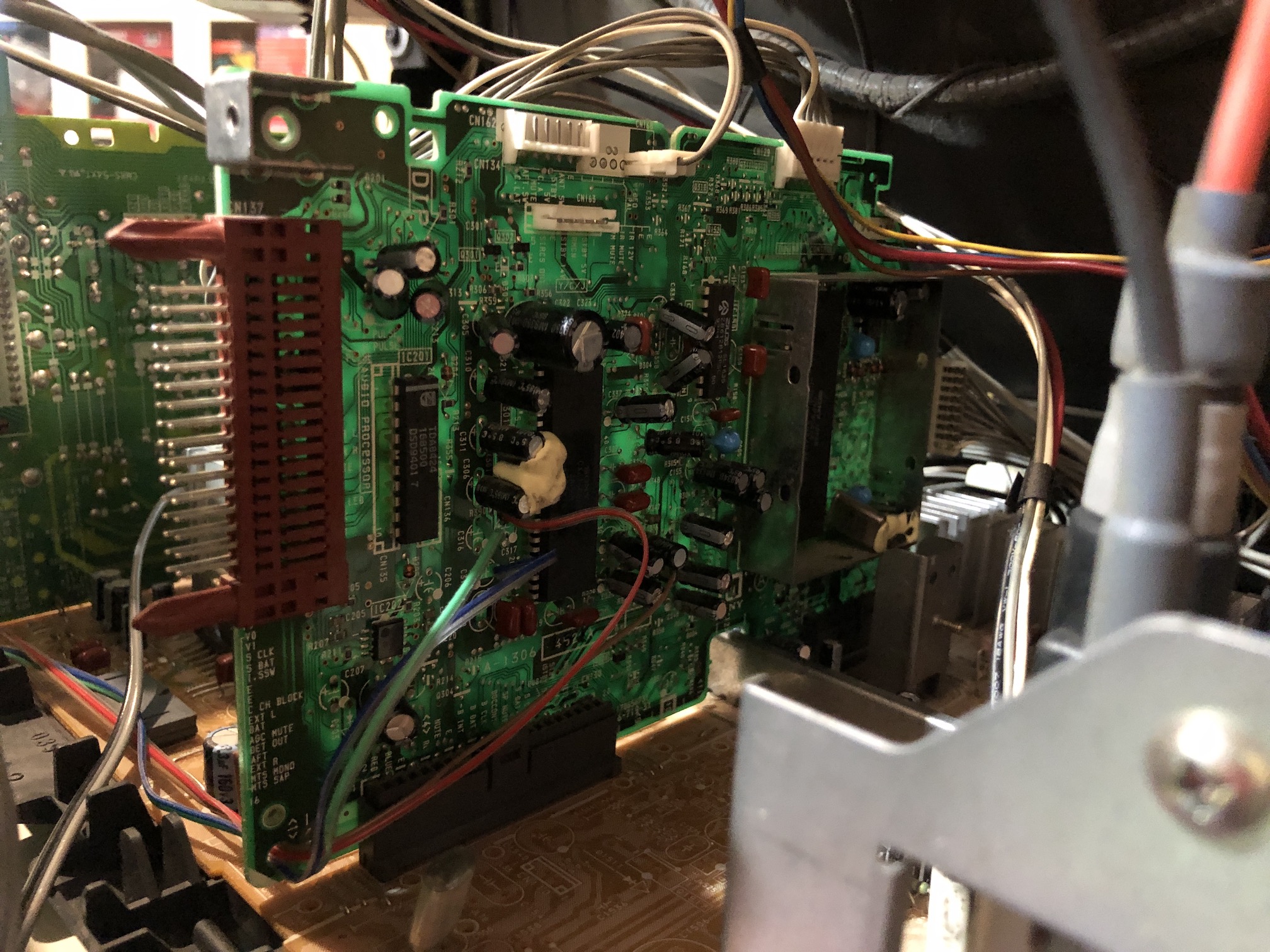
Mount the M board back on the main chassis. Make sure all wires are connected correctly.
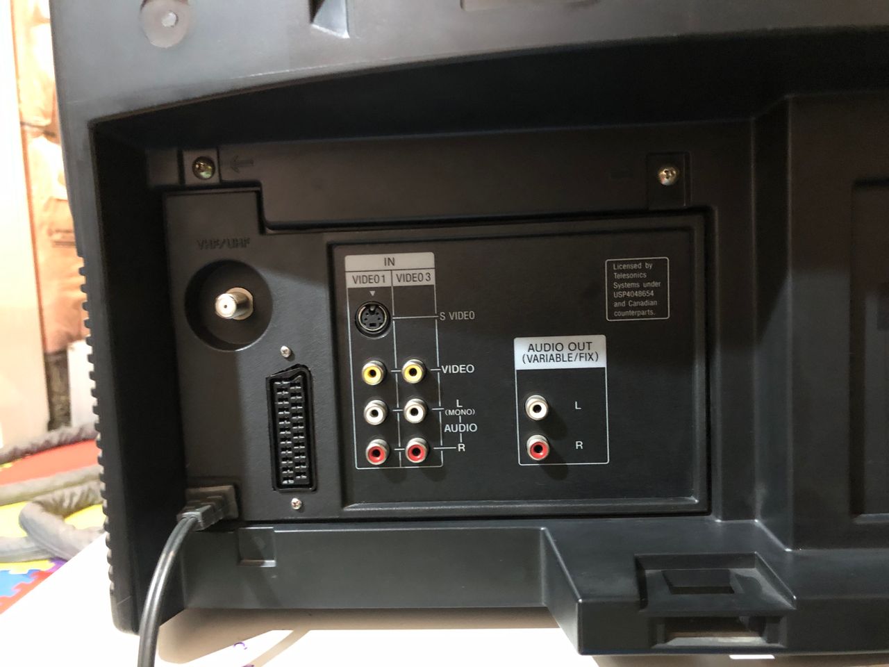
STEP 3: Attach audio and sync wires
On the UA board, connect Audio, ground and sync wires as seen in the below picture 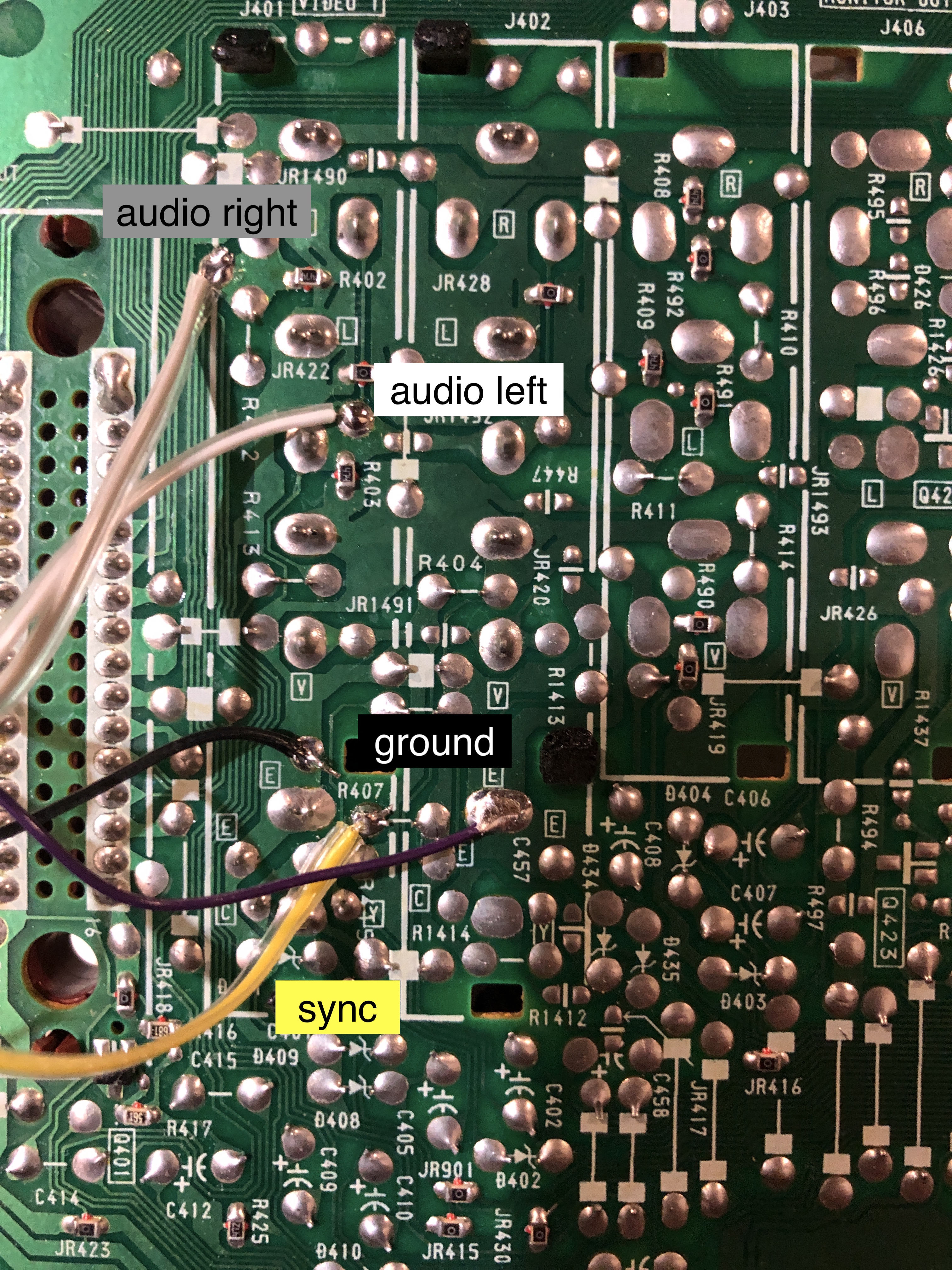
STEP 4: Avoid the need for dummy plugs (optional)
Attaching dummy plugs to enable luma input and stereo can be a hassle and makes the mod look unprofessional. Fortunately, there's another method you can use. This step is optional, and I don't have actual pictures of how to make these changes yet, but it's doable.
Follow the diagram below to ground the S-Video detect pin and cut the trace between the Audio Left and Right channels.
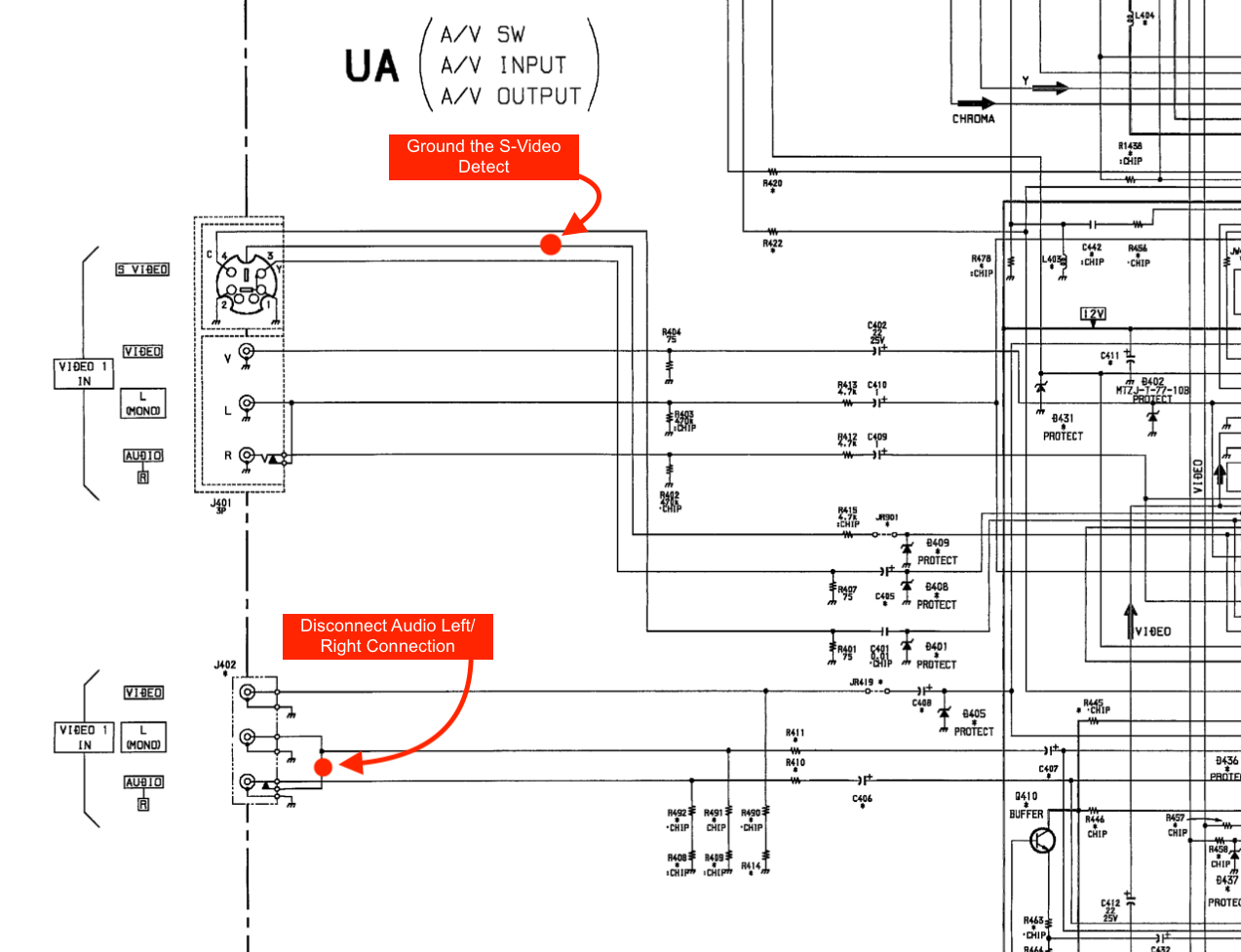
Just remember, after this step, you'll lose the Video 1 composite input and the mono input that outputs to both speakers. You can always use another input like Video 3 for this. For most people, this should be good enough.
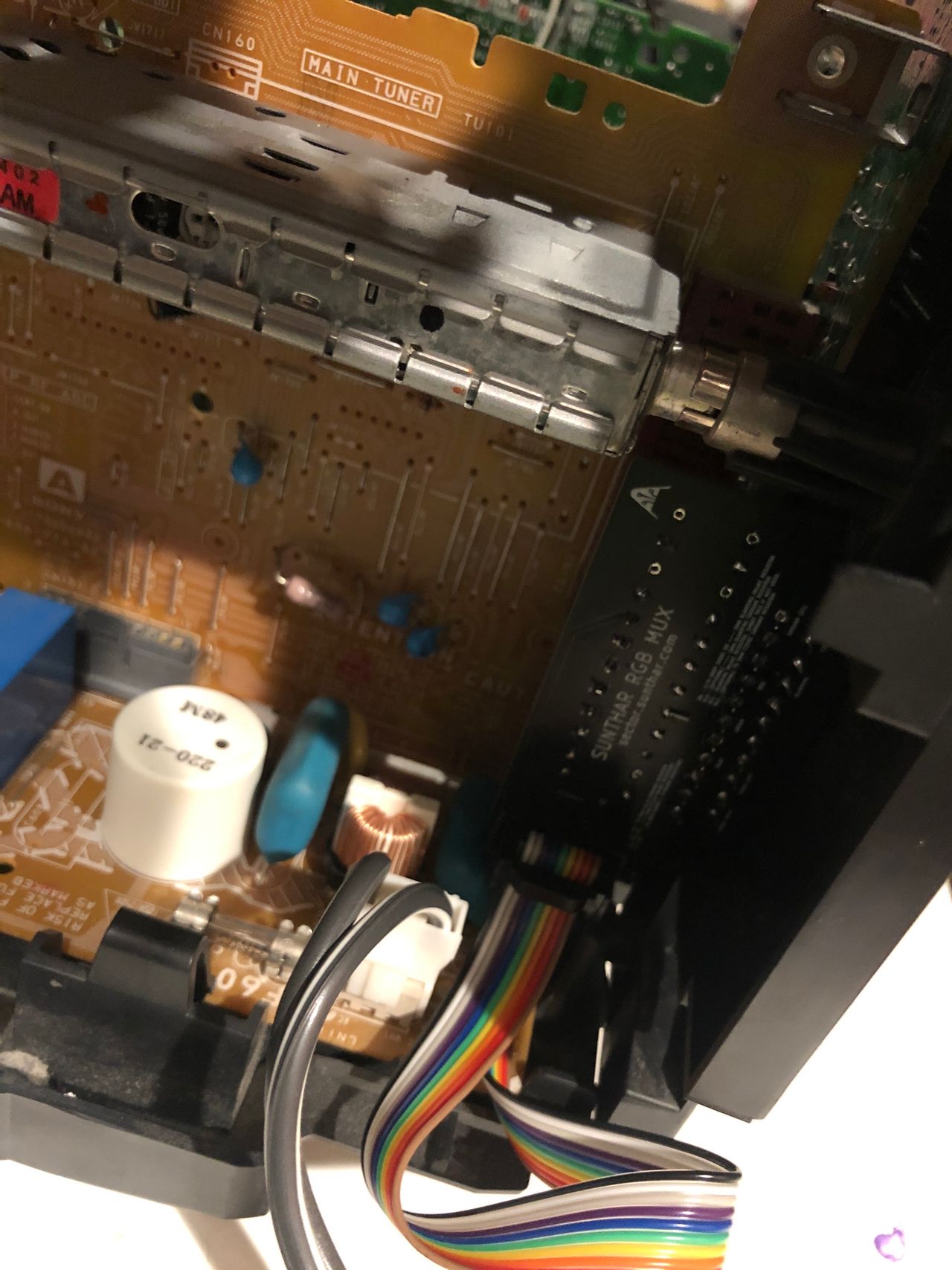
STEP 5: Make your SCART connector circuit
This mod uses the RGB mux board. This is optional, but will make your mod easier and stable. You can also create the circuit presented in the schematics above without the board. Please also checkout the mux calculator to play with your own values.
| On Sony CRT Chassis | KV-27V10 |
|---|---|
| 0.1μF caps replaced | No |
| Add diodes on chassis RGB lines? | No |
| Add blanking diode on chassis | No |
| RGB mux board | KV-27V10 |
|---|---|
| Mux board RGB termination (R1, R2, R3) | 75Ω |
| Mux board RGB input capacitors (R4, R5, R6) | 0.1μF |
| Mux board Audio LR (R7, R8) | 1kΩ |
| Mux board blanking diode (R9) | 1N4148 |
| Mux board blanking ground resistor (R10) | open |
| Mux board blanking resistor (R11) | 4.7kΩ |
| Mux board transistor base resistor (R12) | 1kΩ |
| Mux board transistor (Q1) | PN2222A |
Compatible mux boards:
Radial 0.1uF, 50V ceramic caps were used inline instead of resistors.
Picture of the mini Rev B board 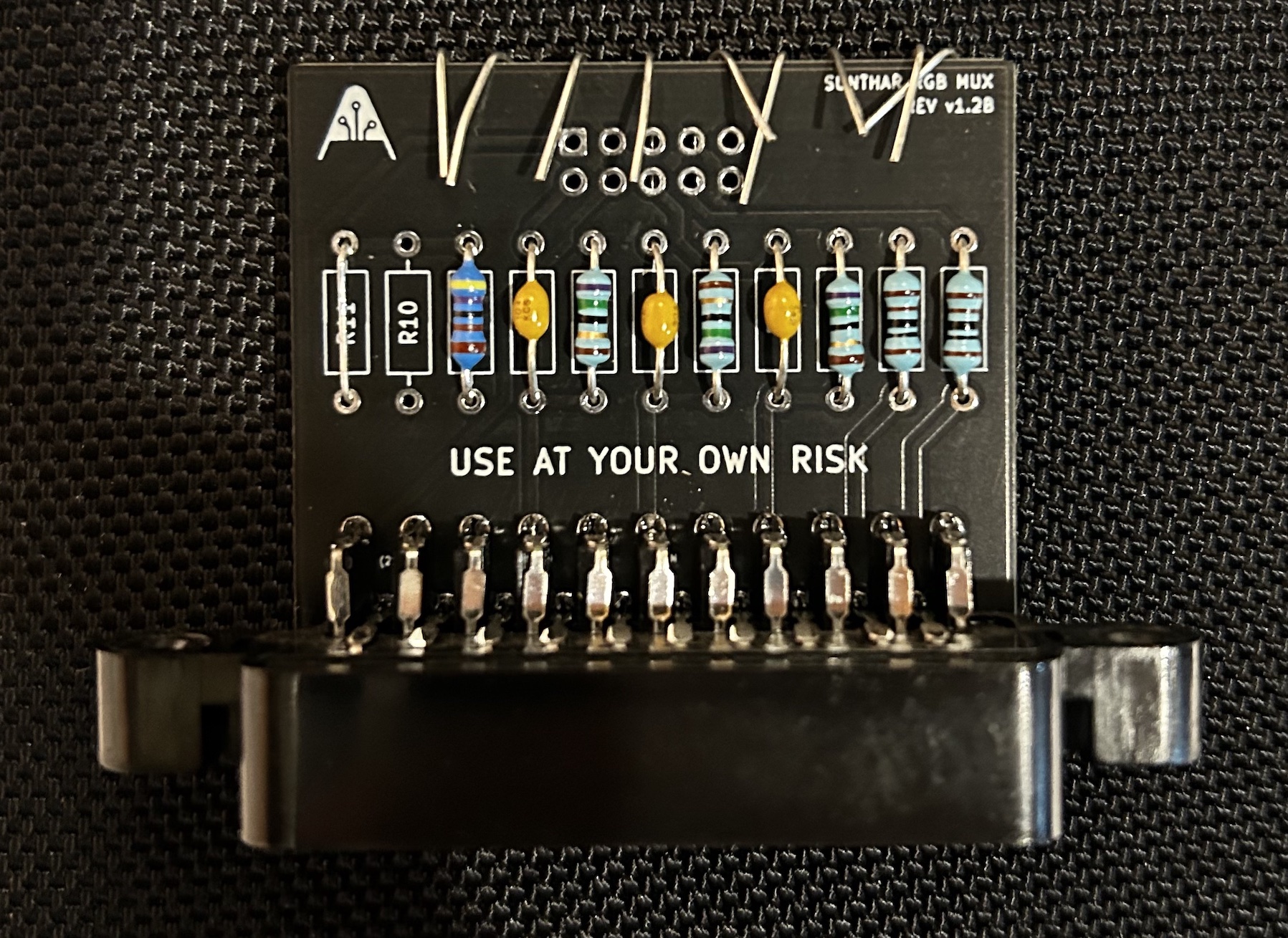
Buy your RGB mux board with the necessary parts to complete this mod
Mouting the SCART adapter to the back is a bit tricky, but not difficult if carefully planned. 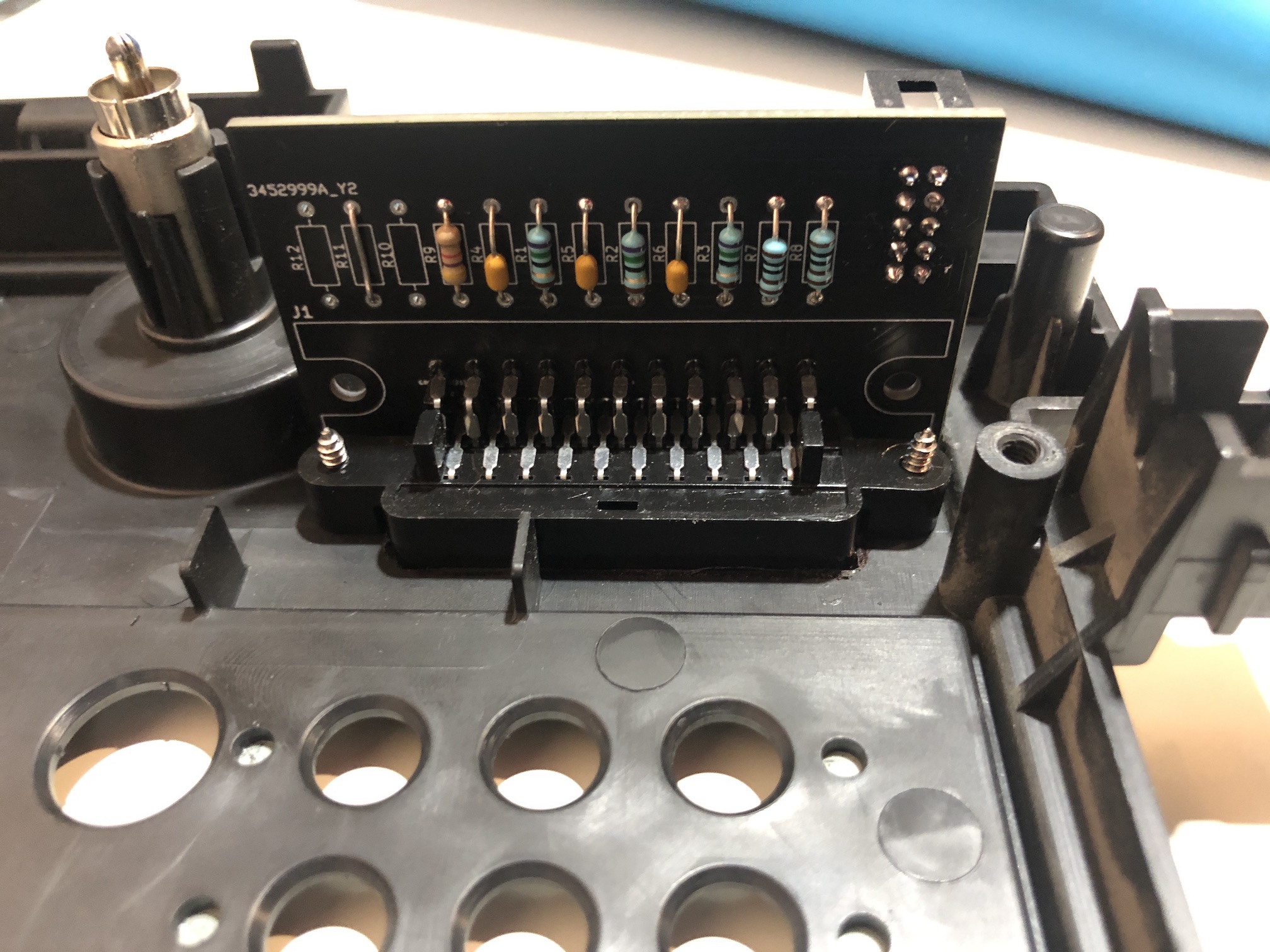
Inside 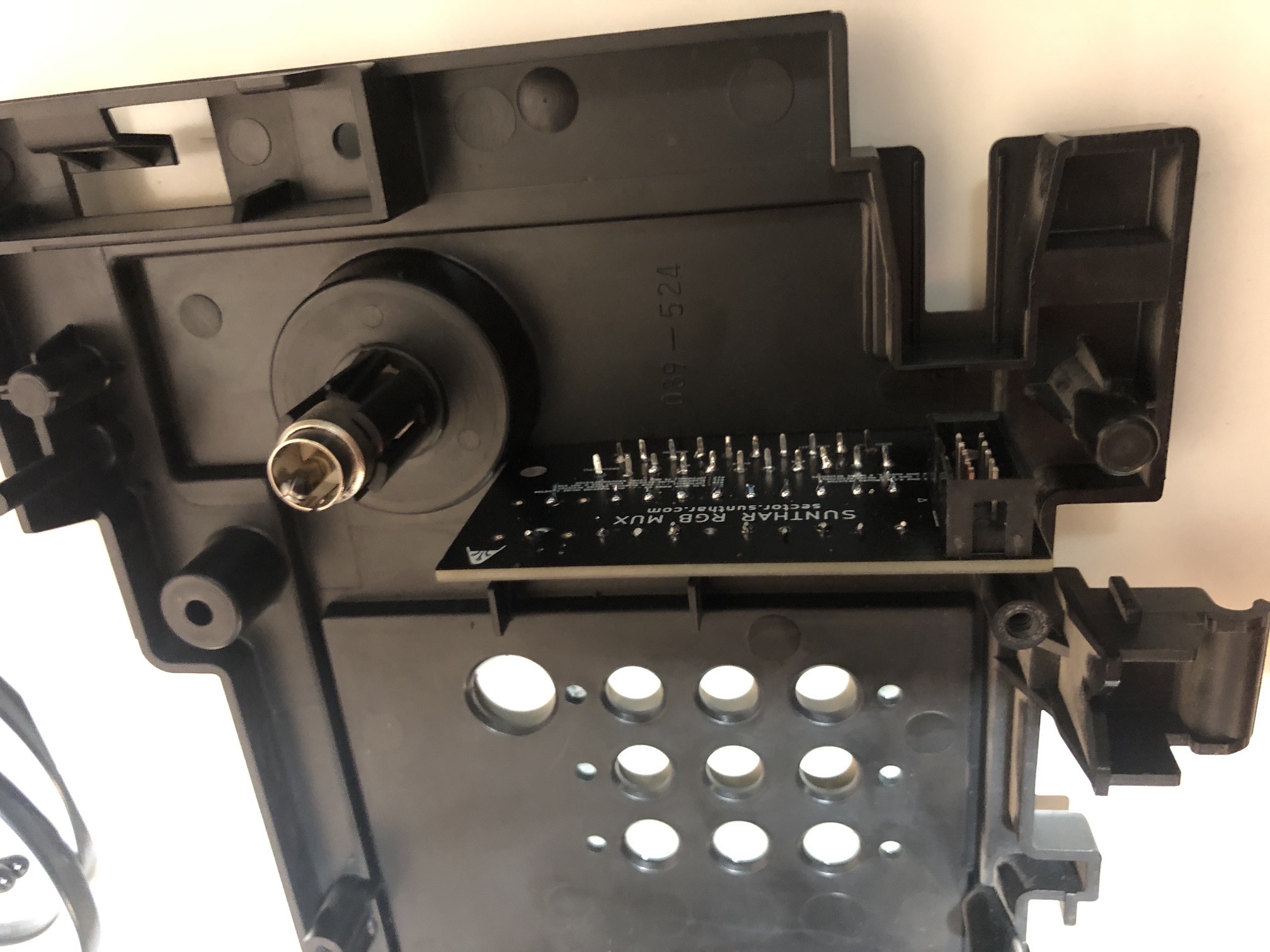
Outside 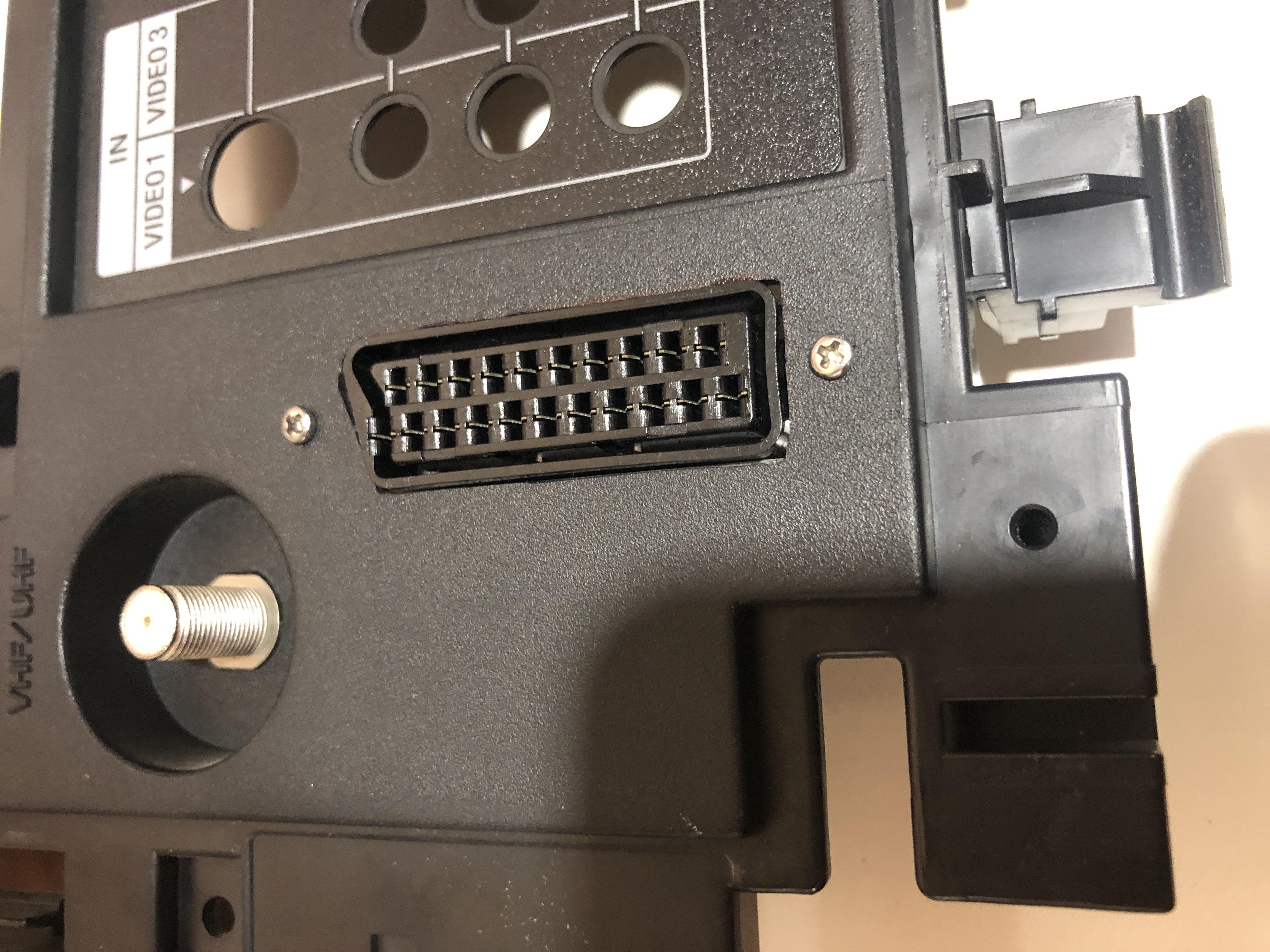
Perfectly fits with the U(A) board 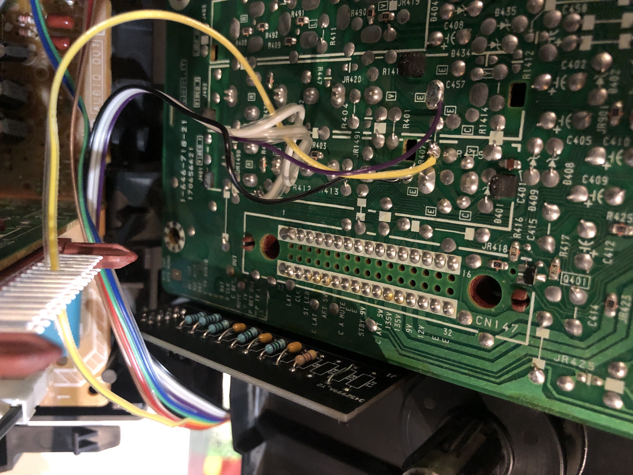
Snug fit once closed 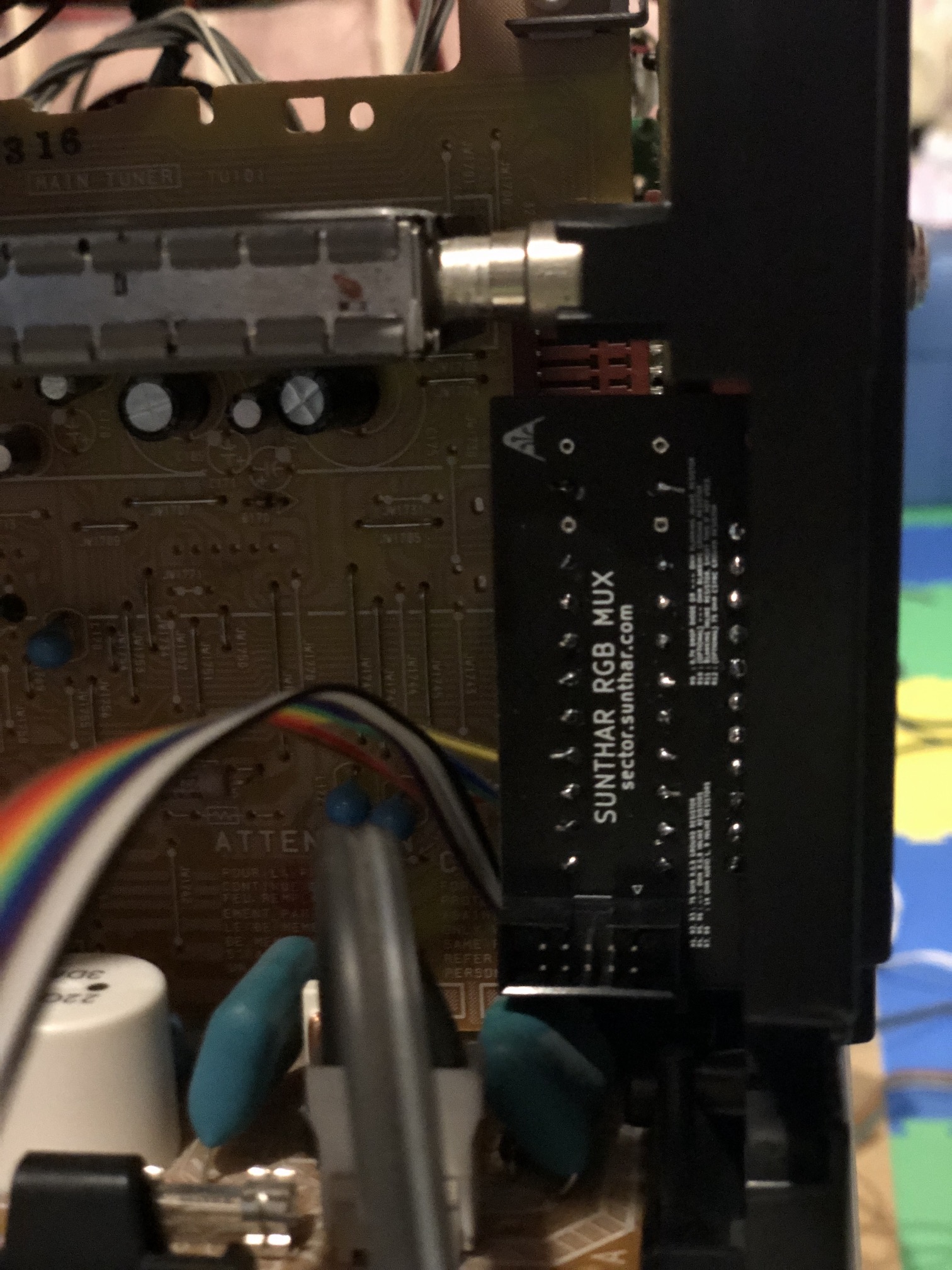
SCART port finished 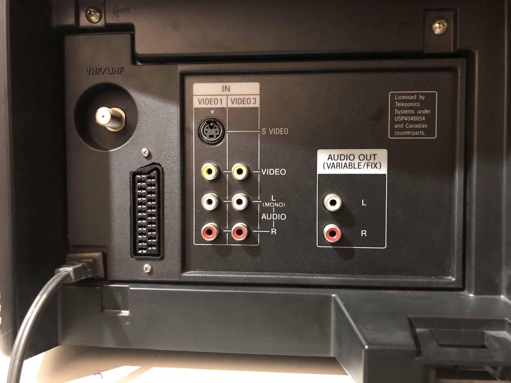
Connector plugged in 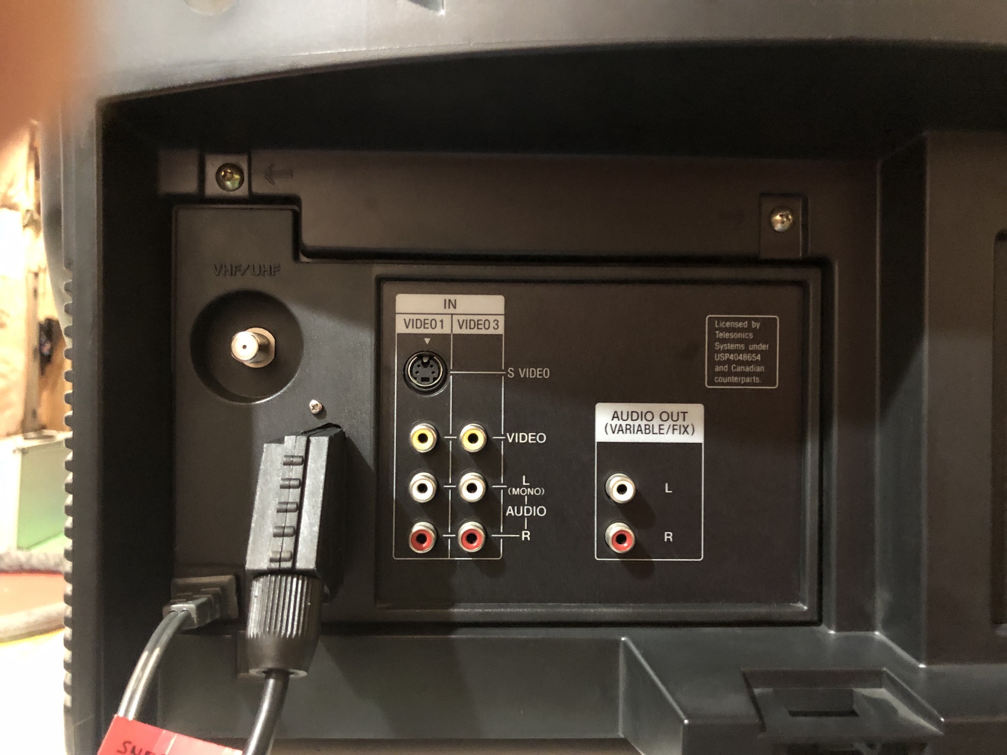
Full back view with SCART port 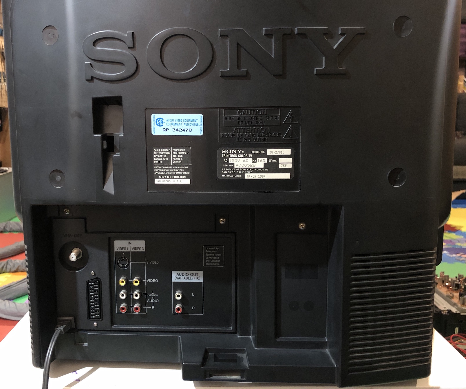
Service Menu Adjustments
If your picture is too dark, try adjusting the RGBP value as per this article
 Sony KV-32V16
Notes
- If you notice shadows after RGB mod, turn OFF velocity modulation and the shadows should go away.
Pictures
OSD
OSD overlay above Megaman X 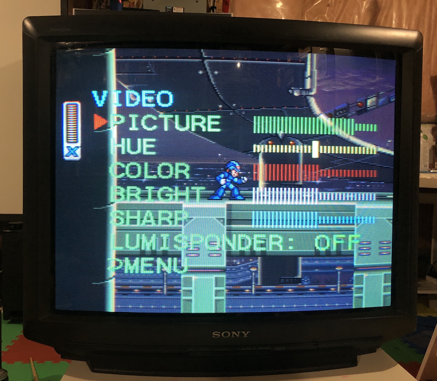
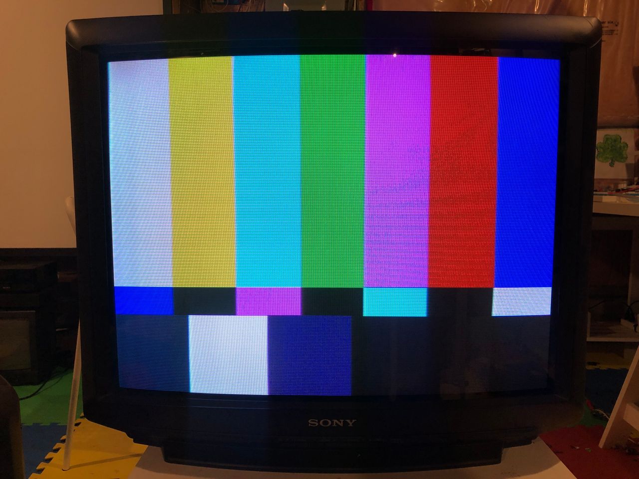
OSD overlay above SMPTE 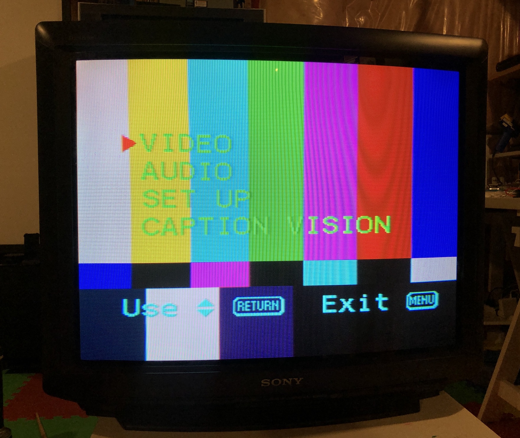
Patterns
SNES 240p Grid 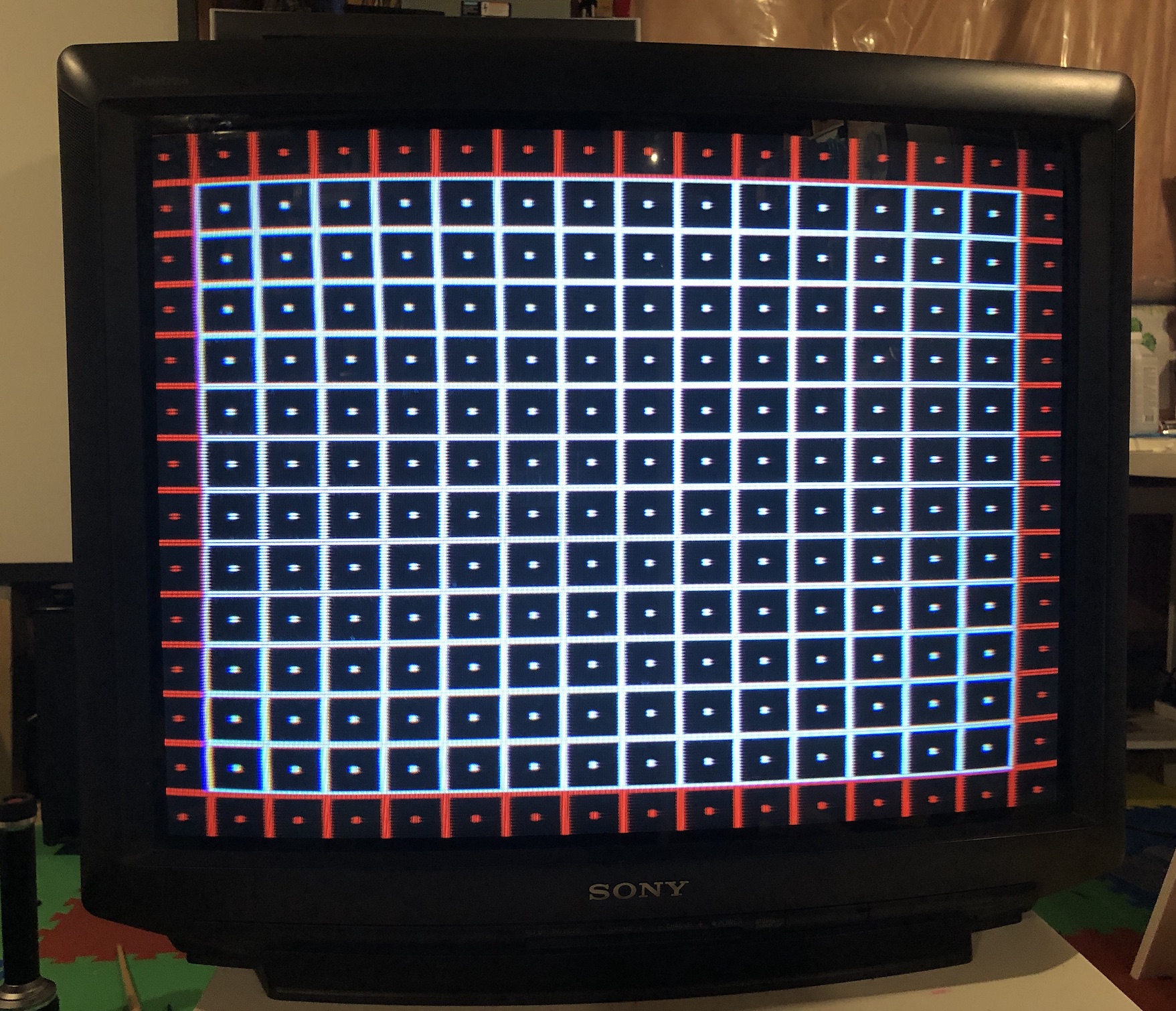
SNES 240p SMPTE 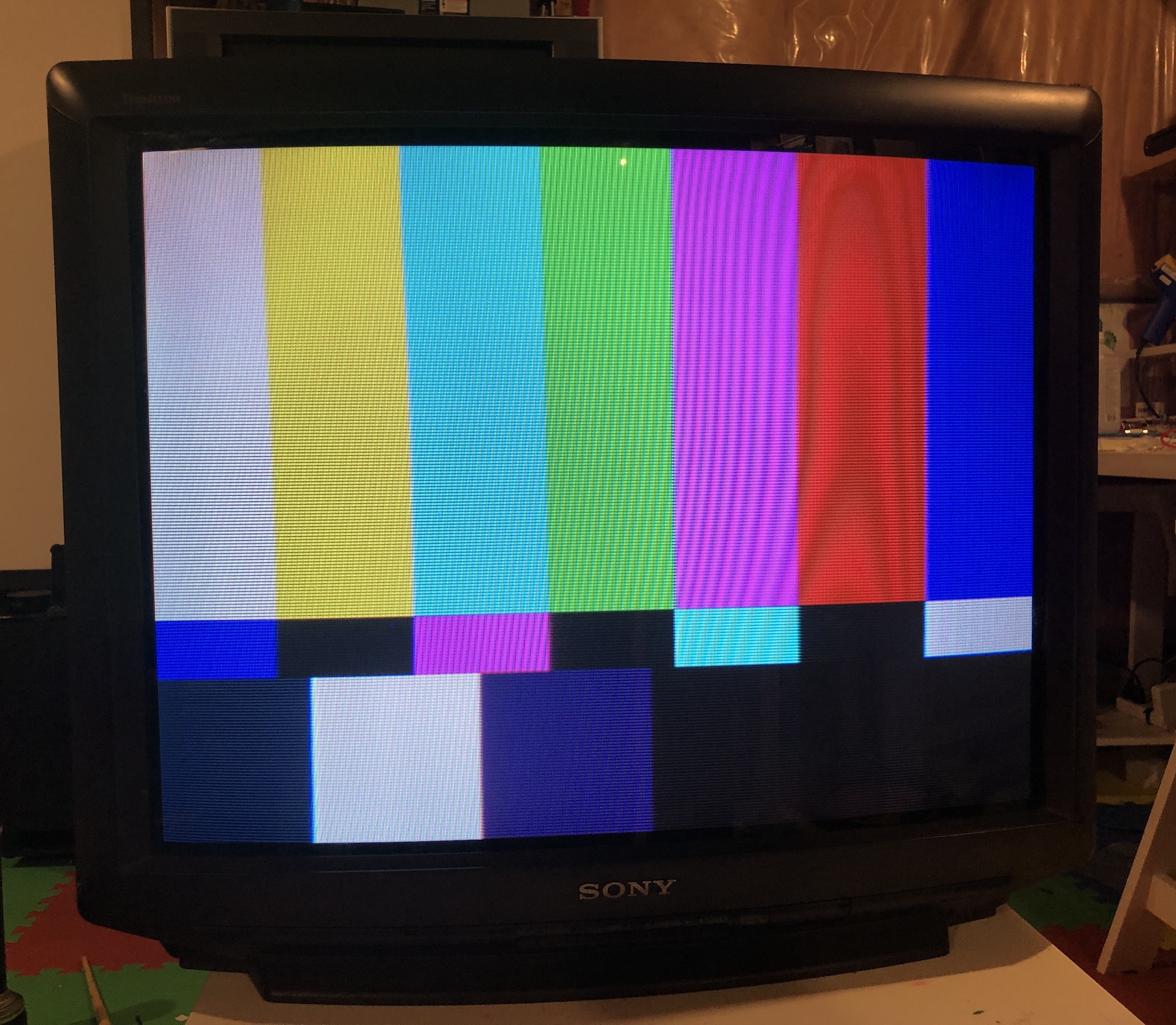
Games
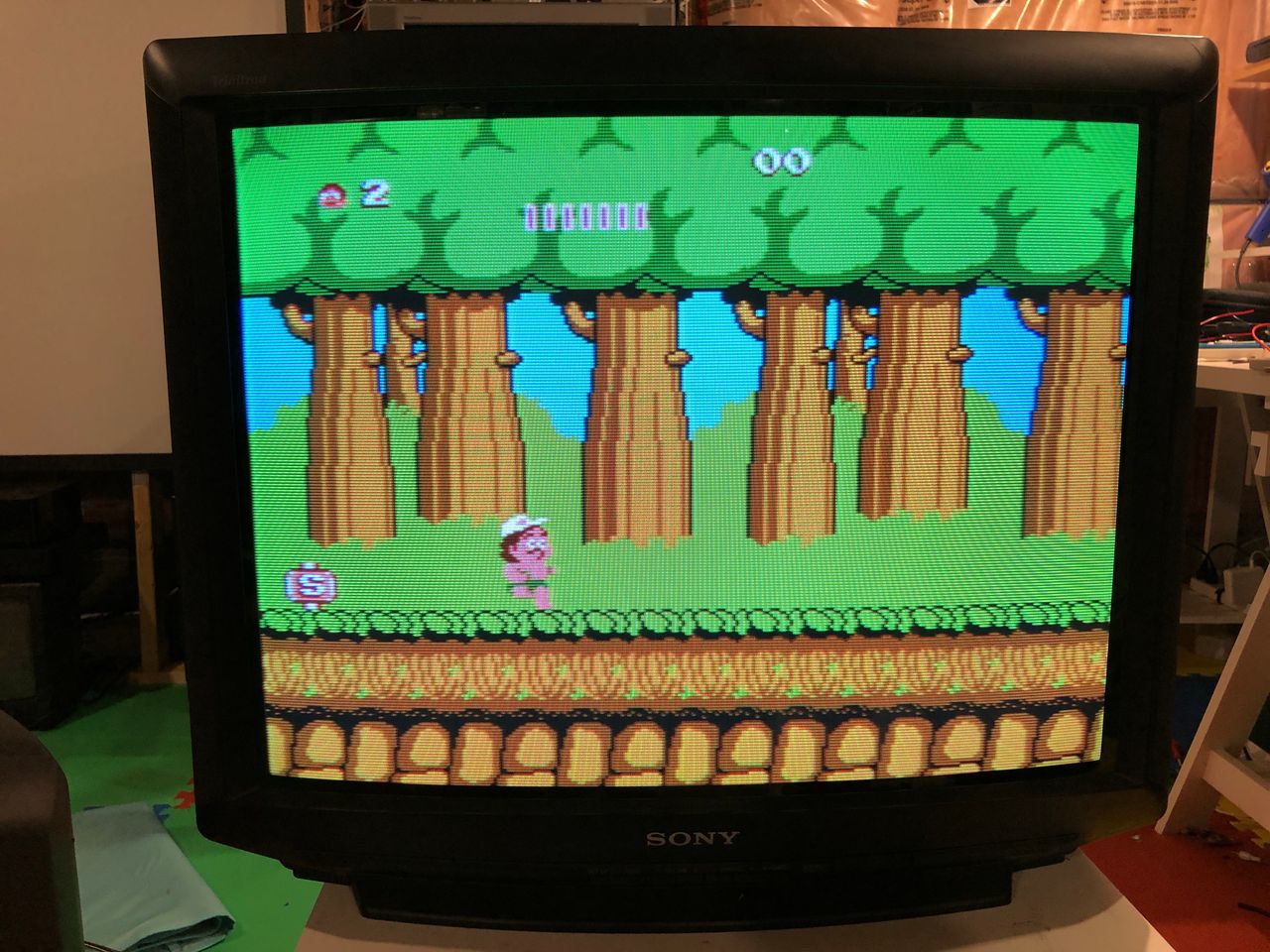
NES - Adventure Island 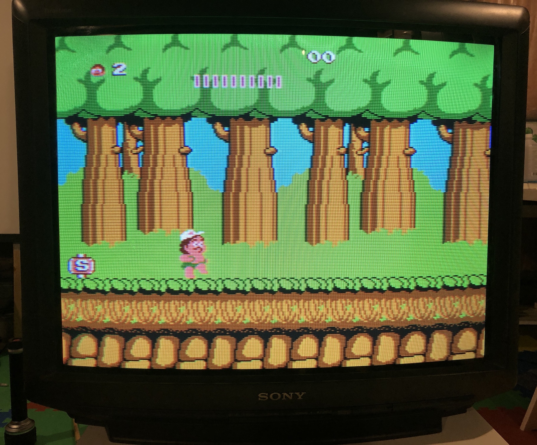
SNES - Mega Man X 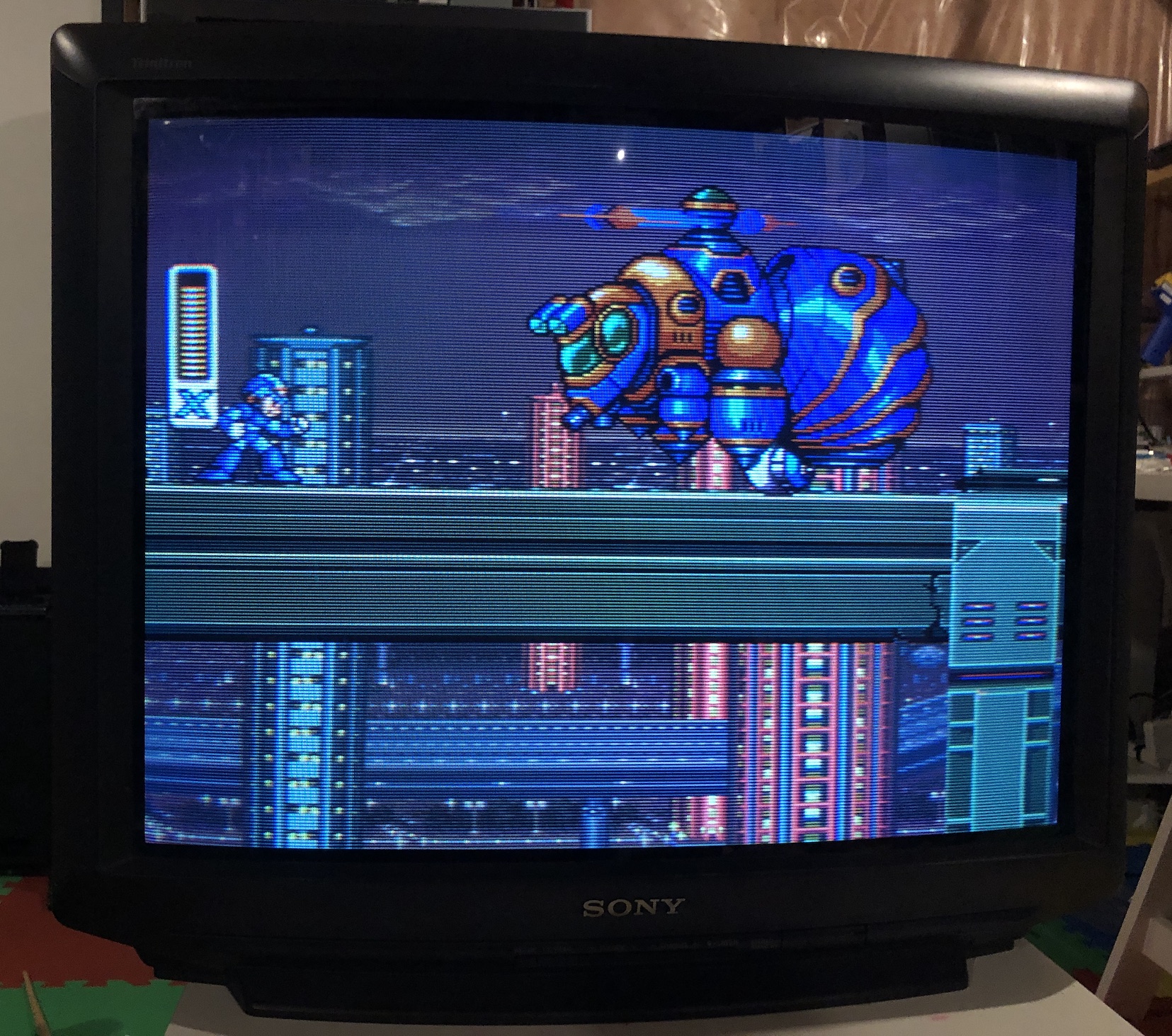
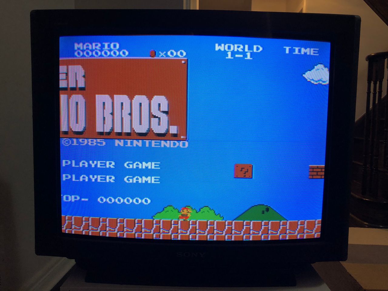
SNES - Super Mario World 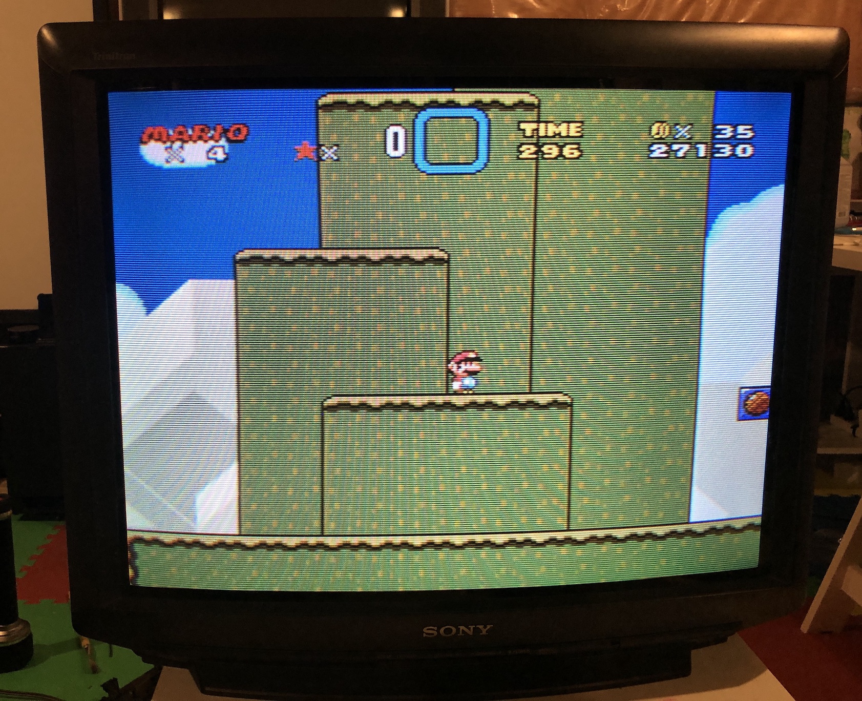
SNES - Super Mario World 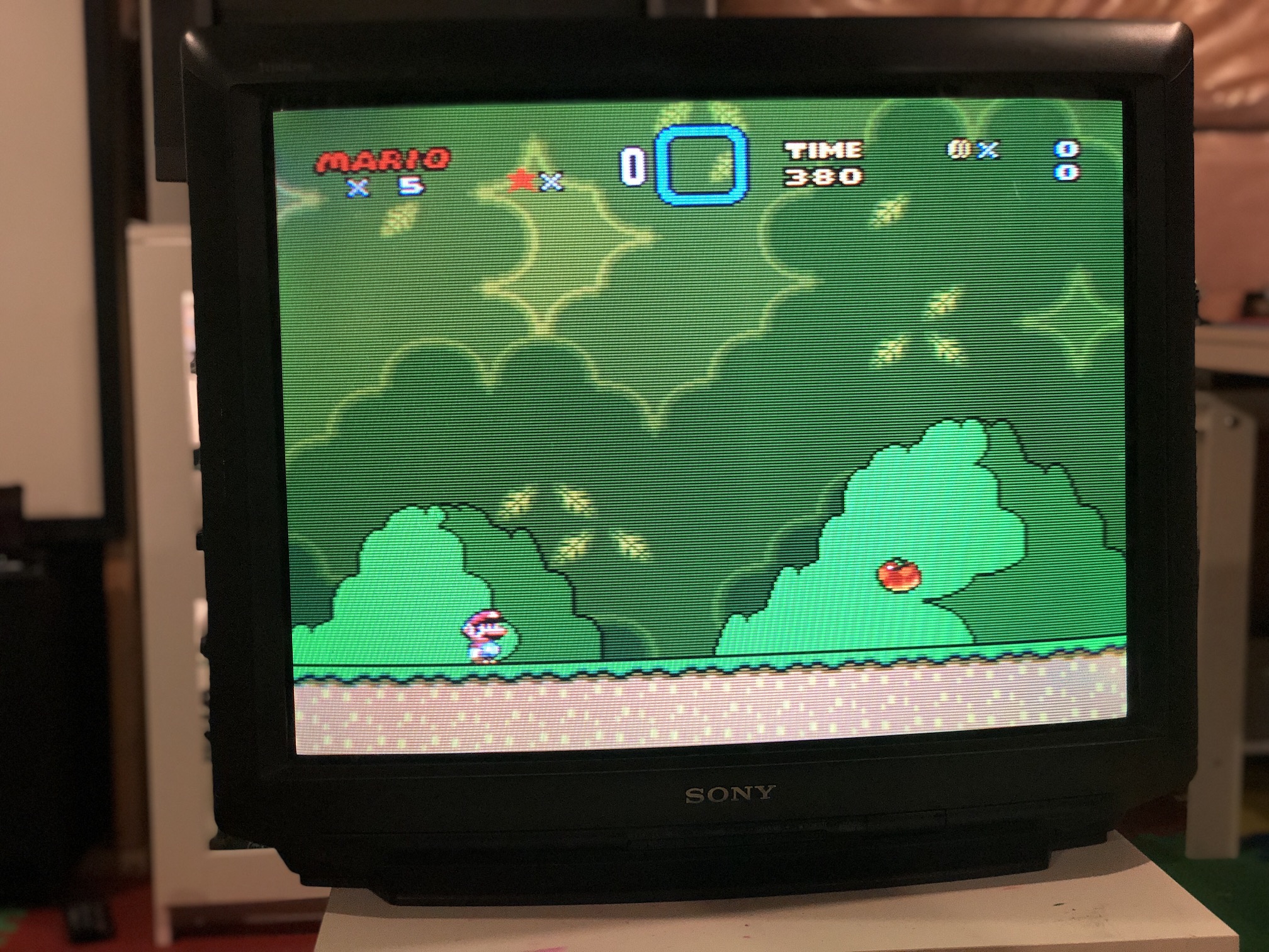
SNES - Super Mario World 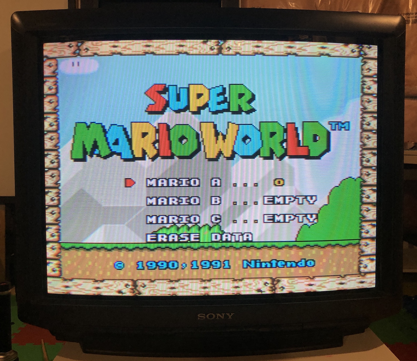
Sega Genesis - Sonic 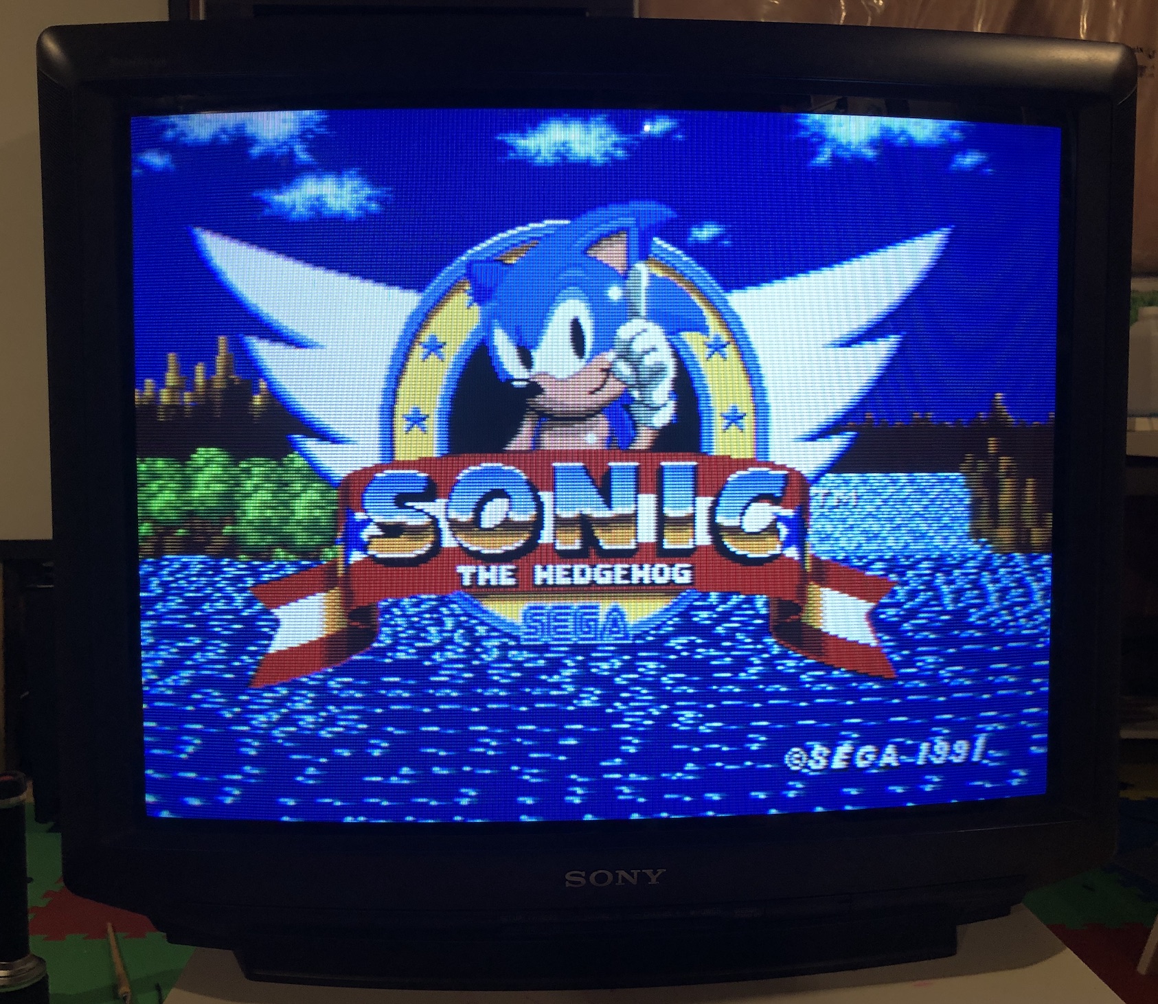
SNES - Super Metroid 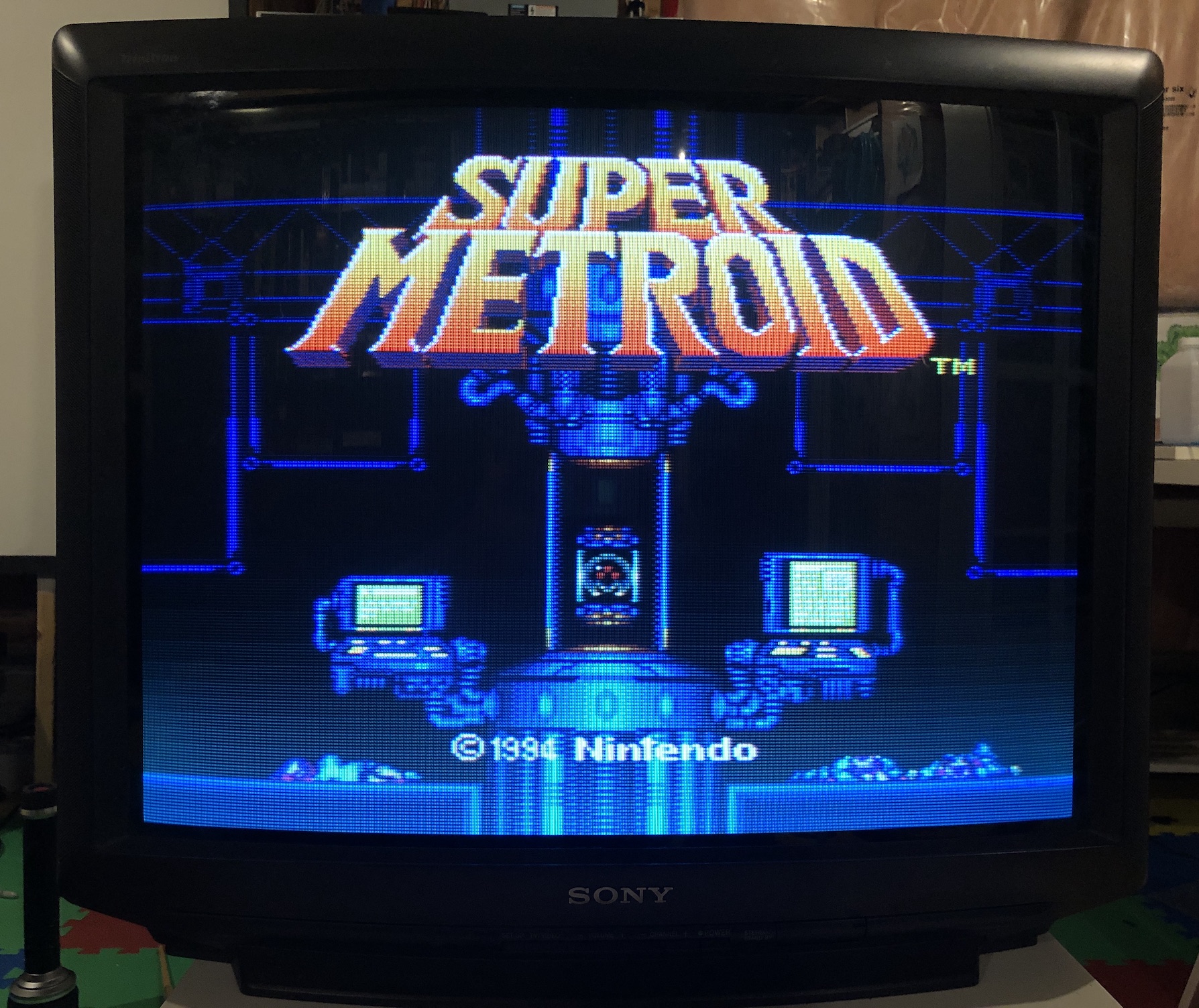
PS1 - Boot 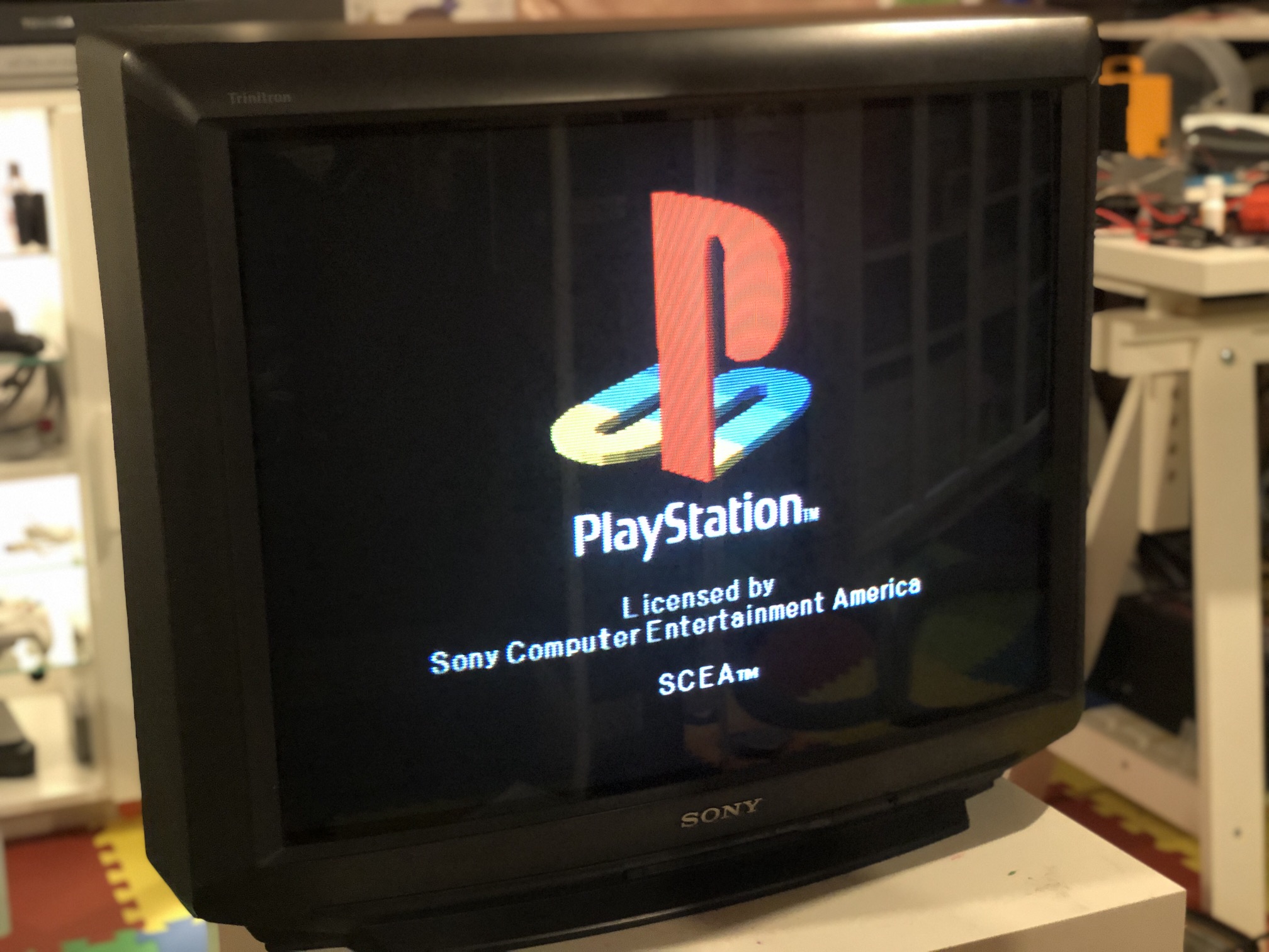
PS1 - Boot 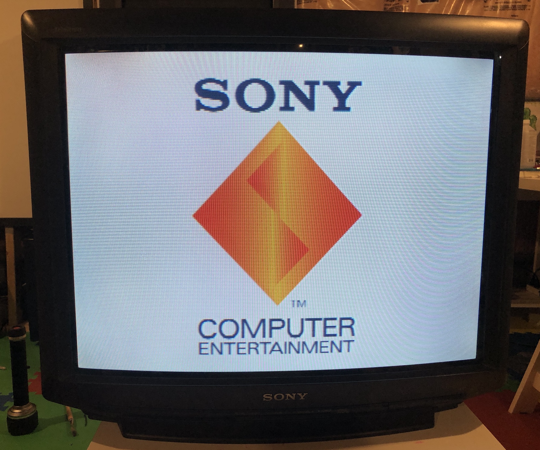
XBOX - UnleashX 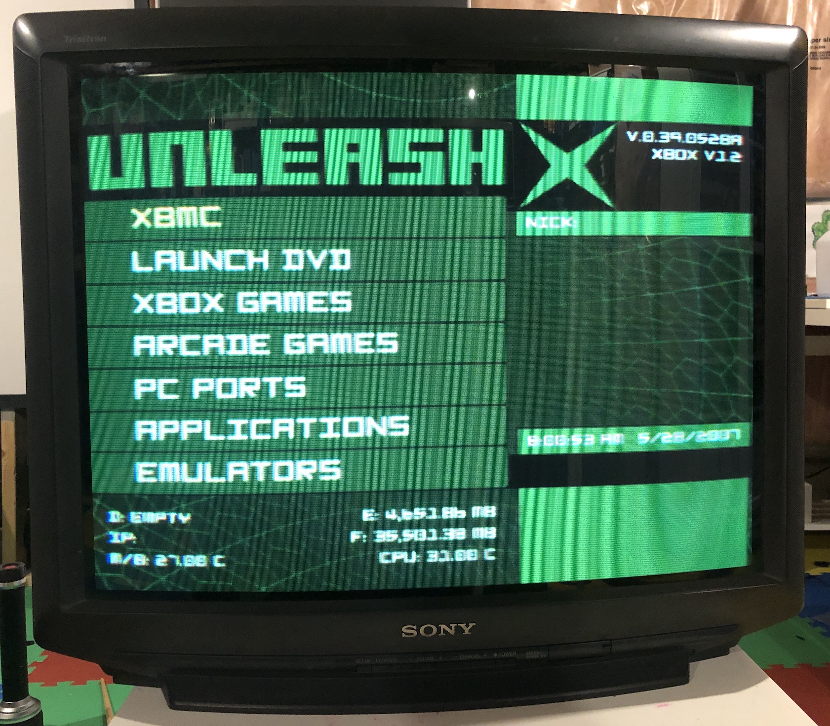
Pictures of the CRT
M Board (before the mod) 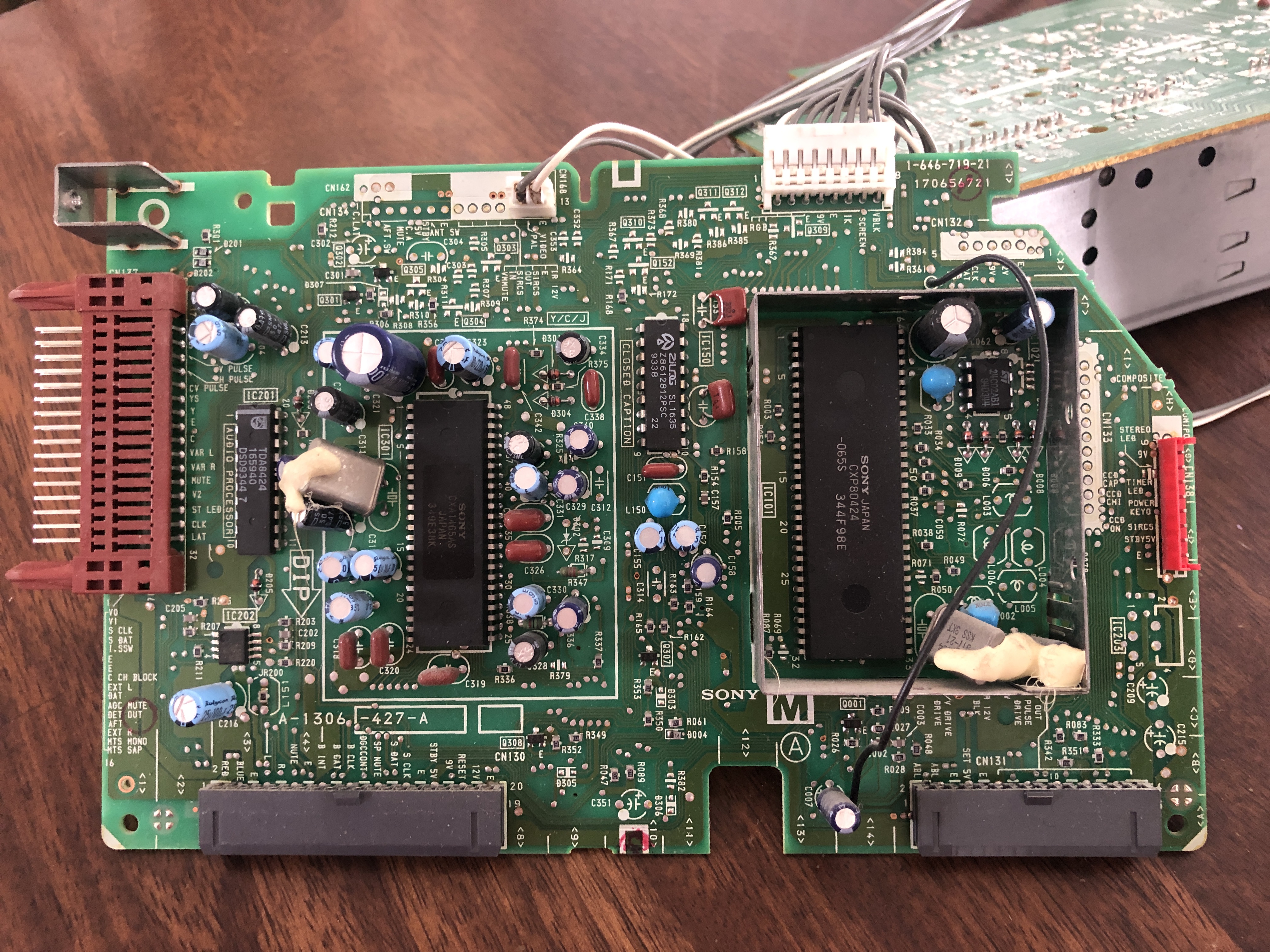
CRT back open (after the mod) 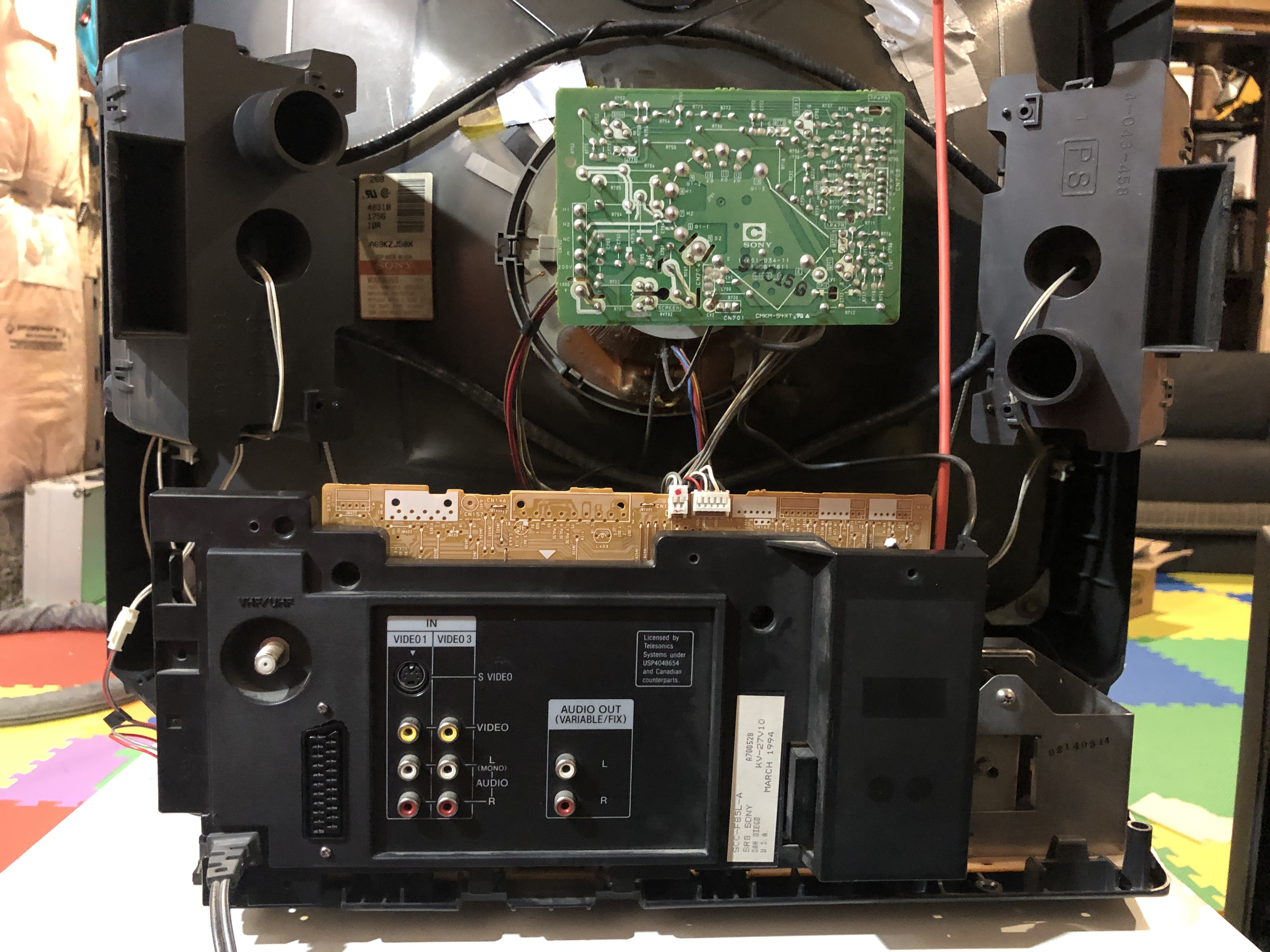
Service Menu Values
NOTE
On KV-27TS36, "ID-2" was changed from 72 to 8 to disable Closed Captioning after the mod was performed, as the Closed Captioning decoder had to be disconnected from the jungle chip RGB and blanking lines as part of the mod.
| NUM | SETTING | VALUE | FIXED |
|---|---|---|---|
| 00 | AFC | 0 | DEFAULT |
| 01 | HFRE | ||
| 02 | H VCO | 3 | DEFAULT |
| 03 | H PHASE | 13 | |
| 04 | AFC GAIN | 6 | DEFAULT |
| 05 | V SHIFT | 2 | DEFAULT |
| 06 | H.SIZE | 24 | |
| 07 | V.SIZE | 31 | |
| 08 | V.LIN | 20 | |
| 09 | VS.CORR | 38 | DEFAULT |
| 10 | R.DRV | 71 | |
| 11 | B.DRV | 71 | |
| 12 | R.BIAS | 142 | |
| 13 | G.BIAS | 142 | |
| 14 | B.BIAS | 142 | |
| 15 | BRI.MAX | 150 | DEFAULT |
| 16 | BRI.CENT | 83 | |
| 17 | BRI.MIN | 50 | DEFAULT |
| 18 | CONT.MAX | 87 | |
| 19 | CONT.CENT | 64 | DEFAULT |
| 20 | CONT.MIN | 16 | DEFAULT |
| 21 | COL.MAX | 90 | DEFAULT |
| 22 | COL.CENT | 65 | |
| 23 | COL.MIN | 00 | DEFAULT |
| 24 | TINT | 55 | |
| 25 | SHARP | 40 | DEFAULT |
| 26 | CB DL | 0 | DEFAULT |
| 27 | CR DL | 0 | DEFAULT |
| 28 | CB PED | 8 | DEFAULT |
| 29 | CR PED | 8 | DEFAULT |
| 30 | PARABOLA | 20 | |
| 31 | CORNER | 33 | DEFAULT |
| 32 | TRAPEZIU | 30 | |
| 33 | LEVEL | 17 | |
| 34 | SEP1 | 6 | |
| 35 | SEP2 | 34 |
Pictures
Reference Photos