Sony (BG-2T) KV-PG14P10
Sony (BG-2T) KV-PG14P10 CRT RGB mod
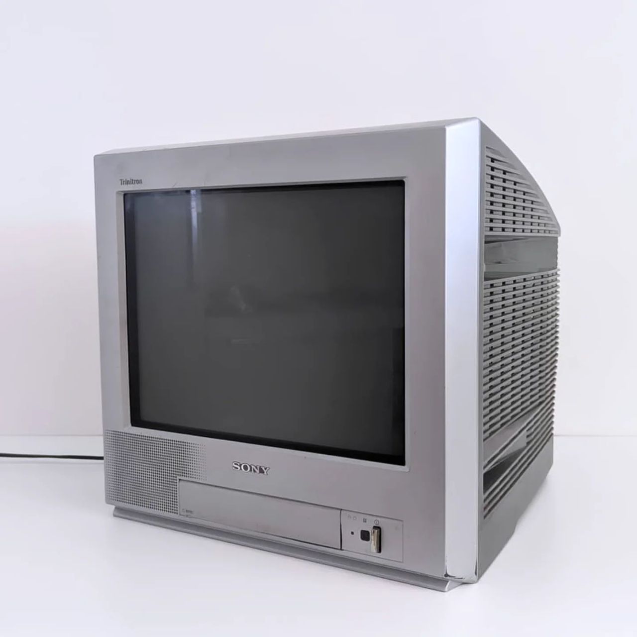
The Sony KV-PG14P10 is a 14" flat Trinitron color CRT television manufactured around 2003. It is part of the BG-2T chassis series, which is RGB moddable.
This CRT is mostly found in the Australian market.
View full CRT details and more mod examples →
Contributors
Thank you to everyone who contributed to this guide:
- Kevin Smith — showcase author
- retropropsau — contributor, Pictures
- TheRetroChannel — contributor, YouTube Video
- Kevin Smith's Sector — contributor, RGB mod and pictures
CRT safety
Caution
You can die doing this! So read carefully! CRT TV is not a toy. Do not open a CRT TV. If you don't have any prior knowledge about handling high voltage devices, this guide is not for you. CRT TV contains high enough voltage (20,000+ V) and current to be deadly, even when it is turned off.
Plan of attack
Manuals and Datasheets
- Sony KV-PG14P10 Service Manual
- Philips TDA8843 Datasheet (Jungle)
- CXP85224A-079S Datasheet (OSD) — Available for Pro Users only. See CRT details for access.
Specs
- Chassis: BG-2T
- Jungle Chip: Philips TDA8843
- OSD Chip: CXP85224A-079S
- Weight: 26.4 lbs
RGB mux diagram
Prepare the mux diagram. If you are building your own circuit, this diagram should help.
Performing the mod
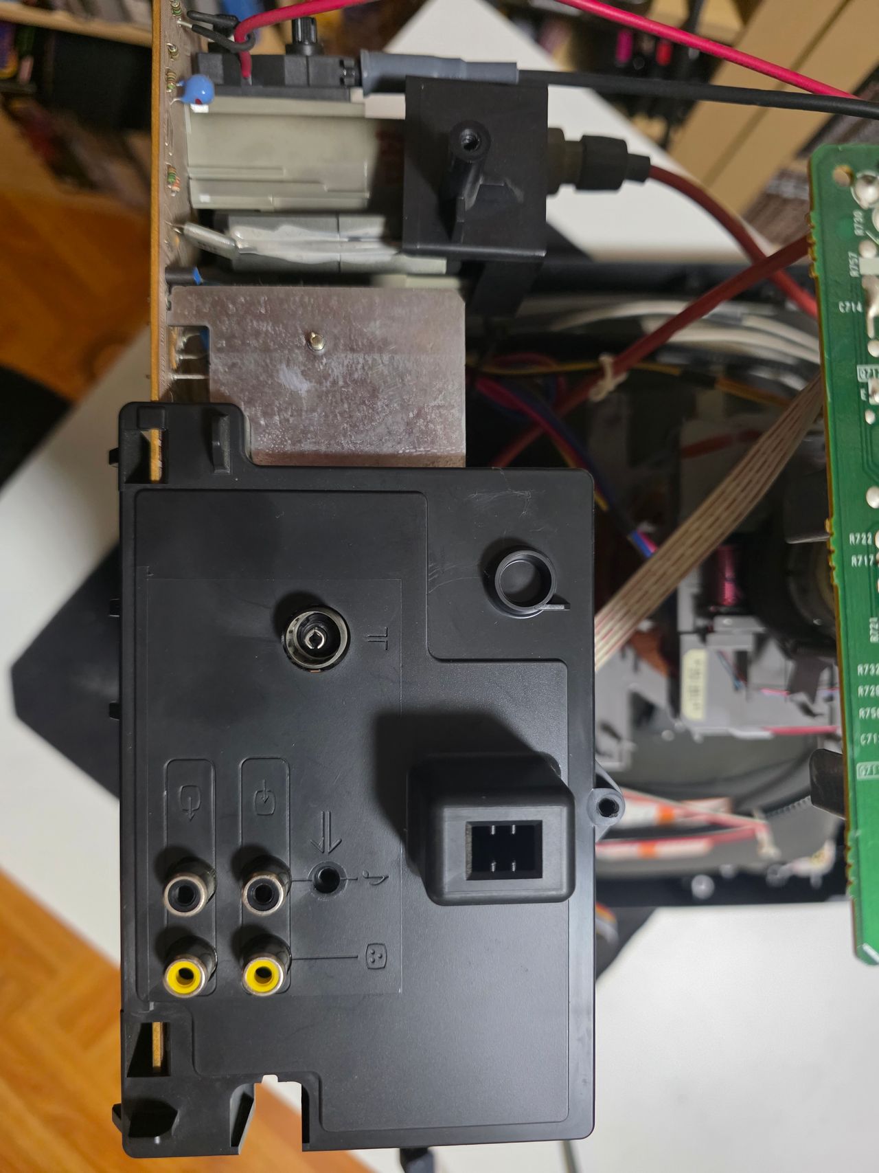
Now that you roughly know what needs to be done, prepare for the mod. Place the board on a comfortable place. Make sure you are not putting pressure on the flyback or other components. Taking out the chassis is fairly straight forward on this CRT. There are few wires that needs to be disconnected.
- Degauss wire
- Power wire
- Ground wire attached to the neck board
- Yoke deflection coil wire
- Anode wire (this is the one with the rubber cap)
- Left and right audio wires
Please remember that wires 1-5 are critical for the CRT to function and should not be omitted. Having any of these wires disconnected while powering up can damage the board and can have adverse effects.
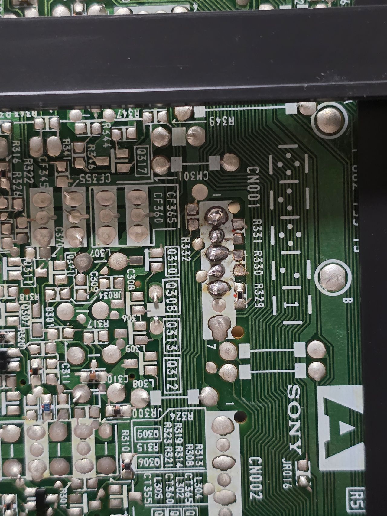
STEP 1: Remove the following components
Remove the three (0Ω) ground resistors or jumpers if present.
- R330
- R331
- R332
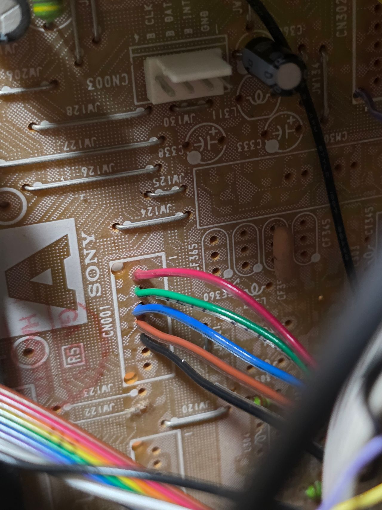
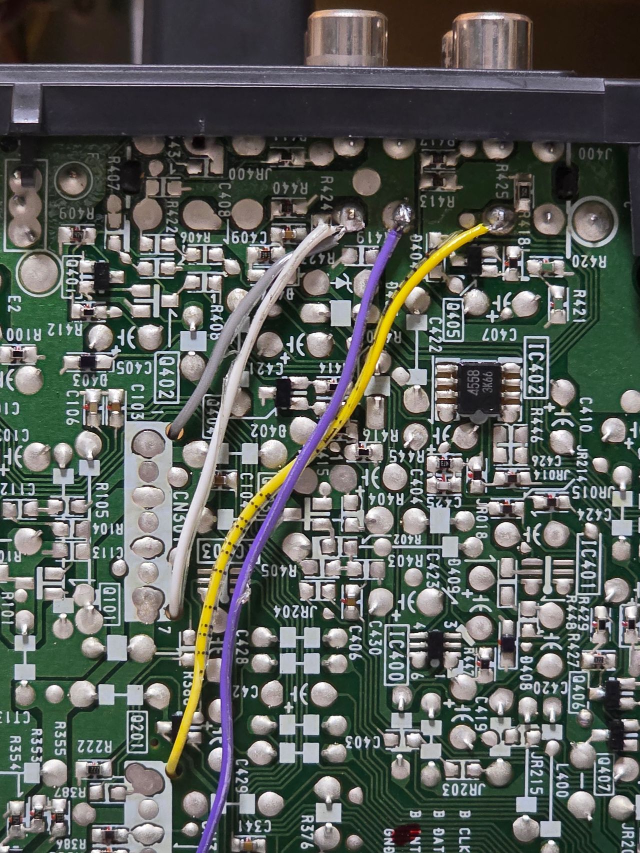
STEP 2: Connect RGB, Blanking and Ground
Connector CN001 can be utilized to inject R, G, B, Blanking and ground.
STEP 3: Connect Audio and Sync
STEP 4: Build your mux board
This mod uses the RGB mux board. This is optional, but will make your mod easier and stable. You can also create the circuit presented in the schematics above without the board. Please also checkout the mux calculator to play with your own values.
| On Sony CRT Chassis | KV-PG14P10 |
|---|---|
| CRT RGB inline resistor | 390Ω |
| CRT RGB ground resistors removed | 0μF |
| 0.1μF caps replaced | No |
| Add diodes on chassis RGB lines? | No |
| Add blanking diode on chassis | No |
| Replace blanking resistor on chassis | No |
| RGB mux board | KV-PG14P10 |
|---|---|
| Mux board RGB termination (R1, R2, R3) | 75Ω |
| Mux board RGB inline resistors (R4, R5, R6) | 390Ω |
| Mux board Audio LR (R7, R8) | 1kΩ |
| Mux board blanking diode (R9) | 1N4148 |
| Mux board blanking ground resistor (R10) | open |
| Mux board blanking resistor (R11) | 560Ω |
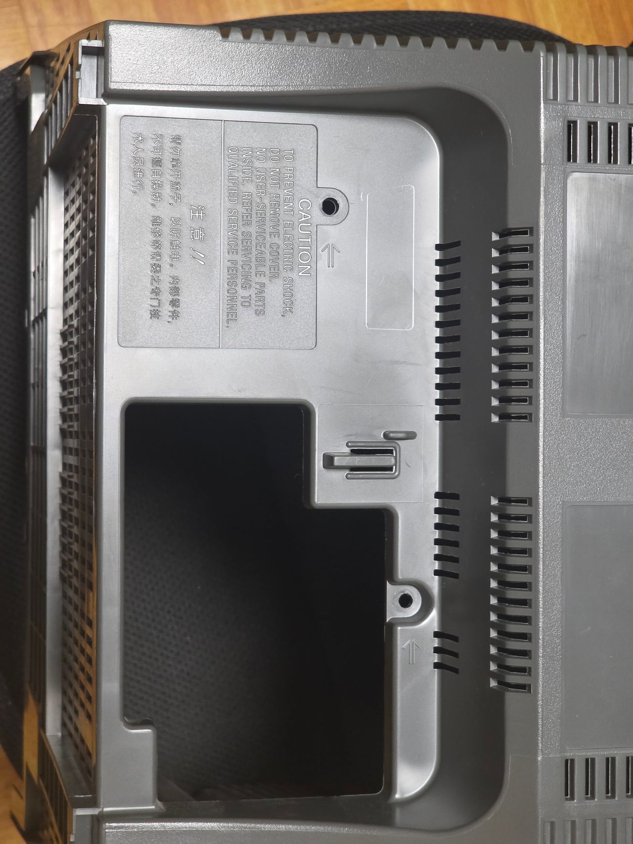
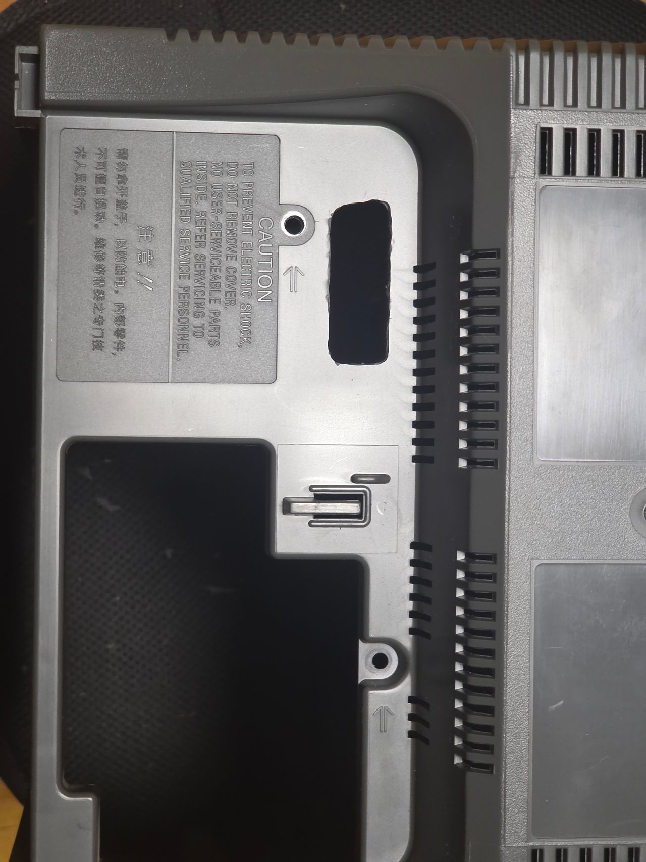
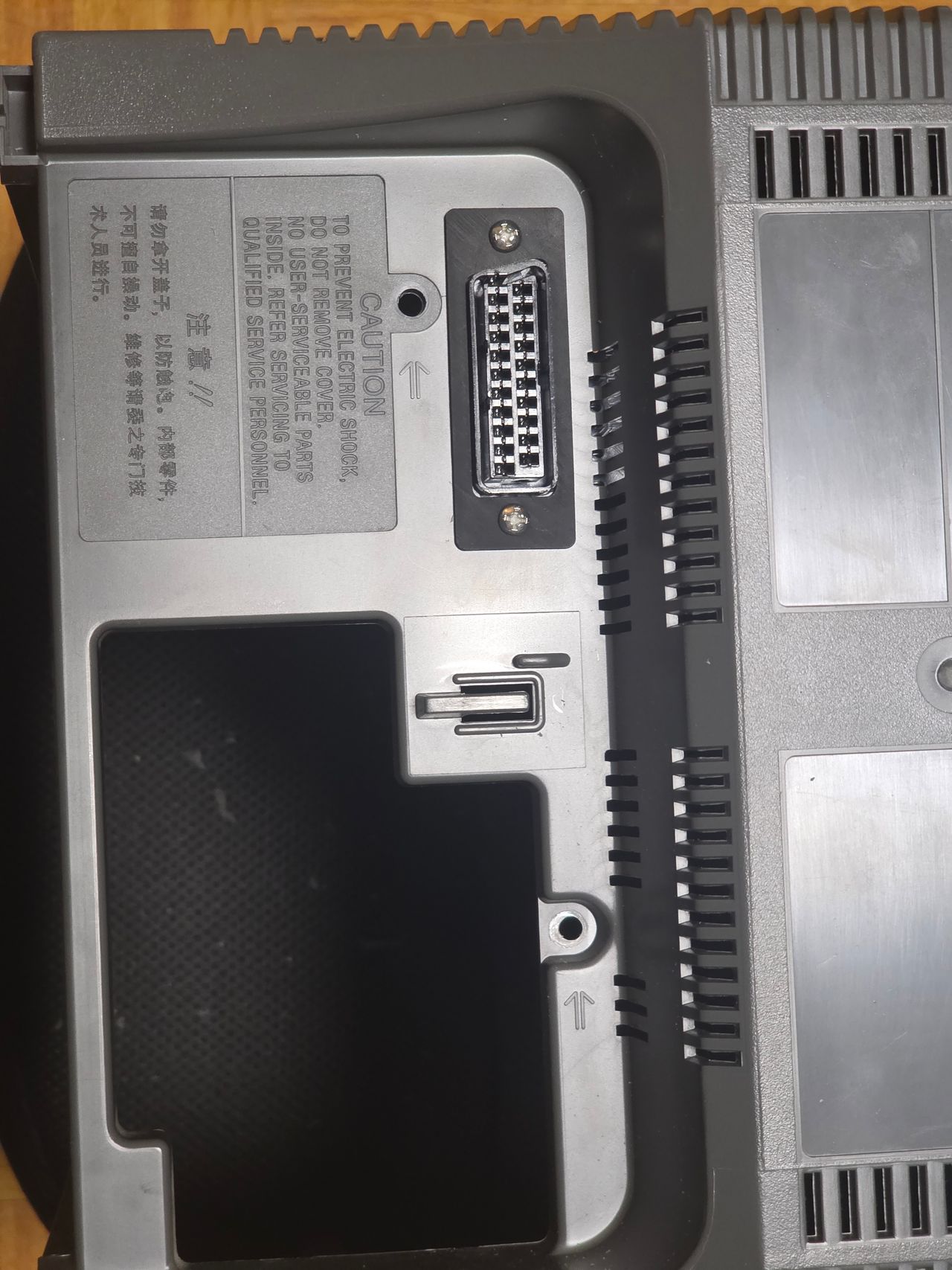
STEP 5: Attach the female SCART connector to TV
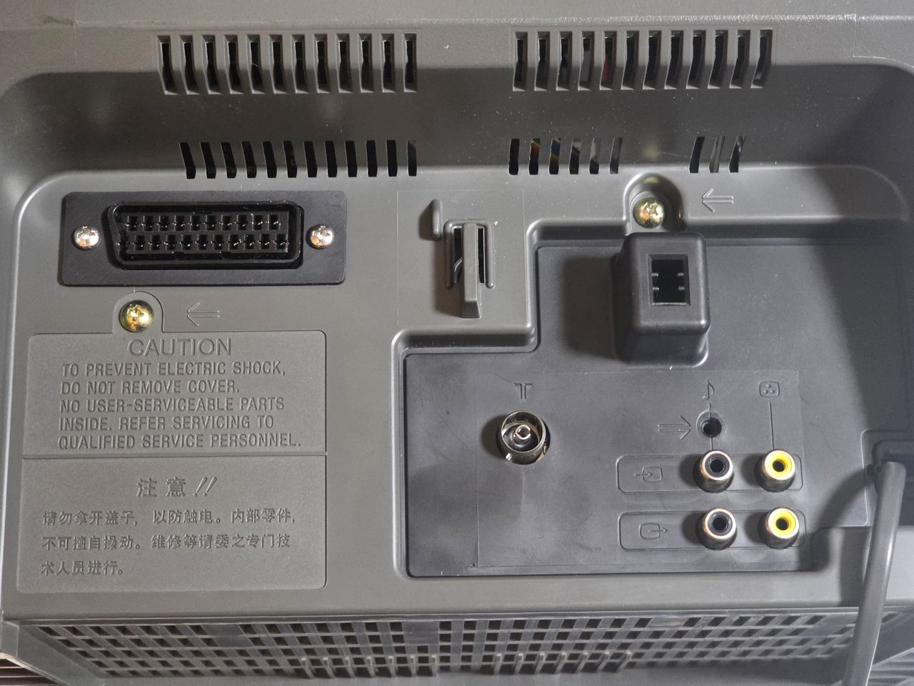
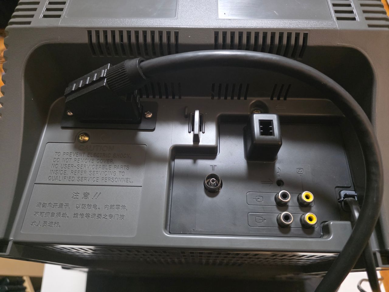
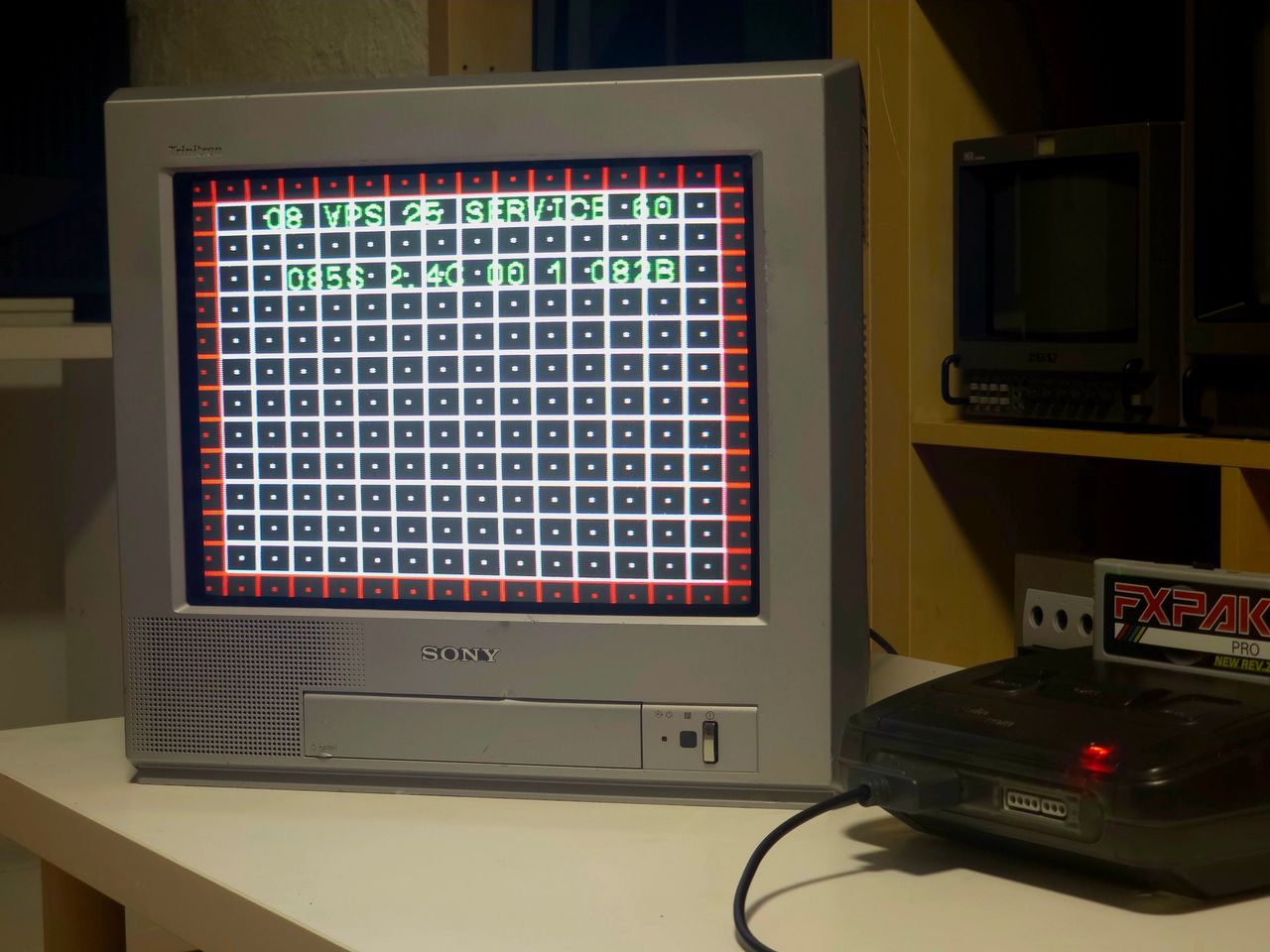
Pictures
Photos by Kevin Smith
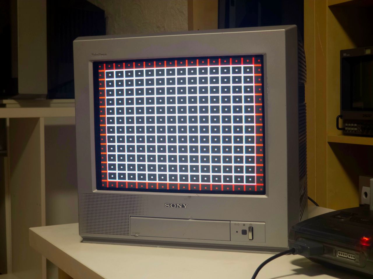
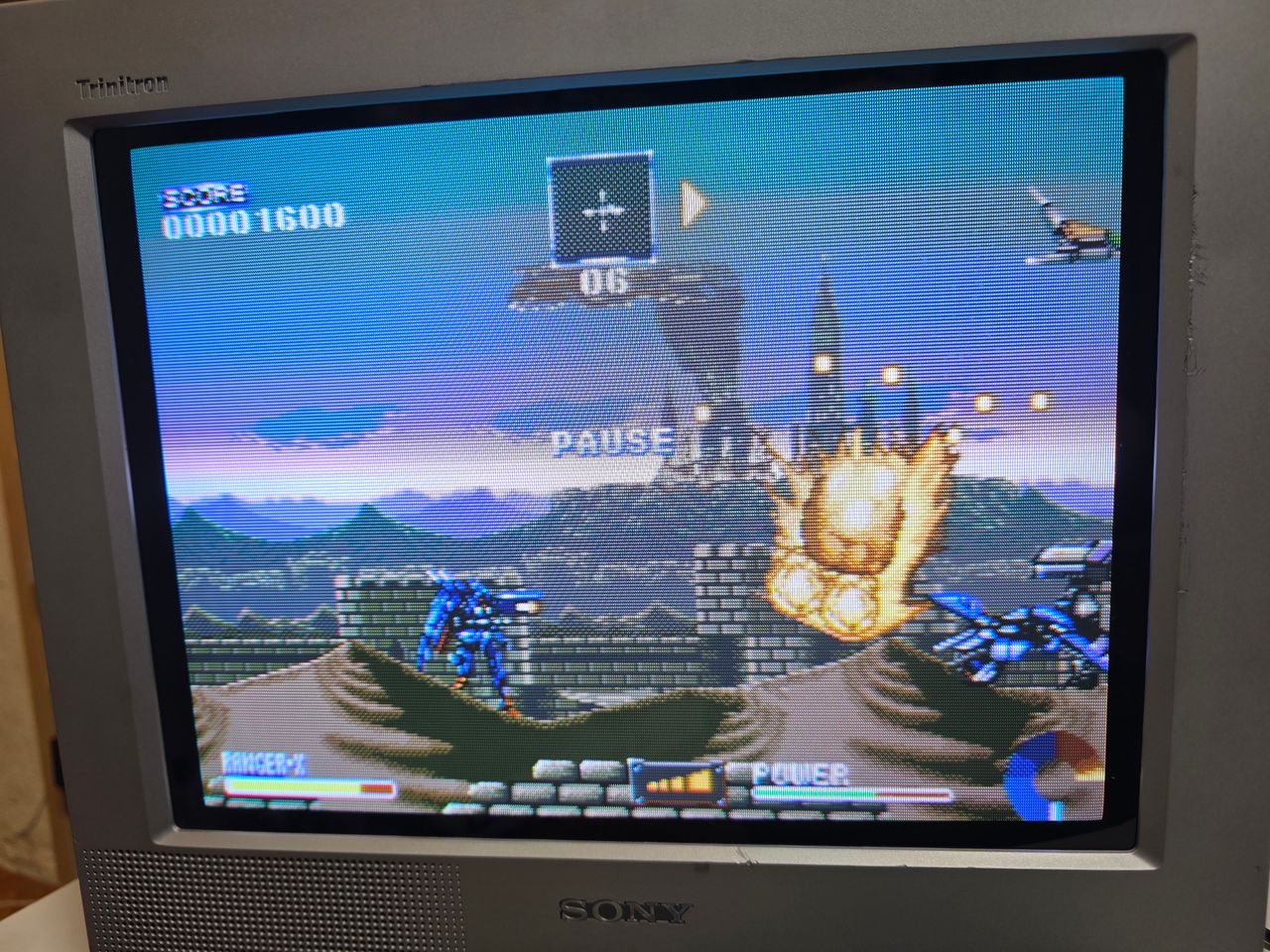
RGB modification showcase of a Sony KV-PG14P10 CRT.

Reference Photos