Sony (AA-2) KV-32V35
Sony (AA-2) KV-32V35 CRT RGB mod
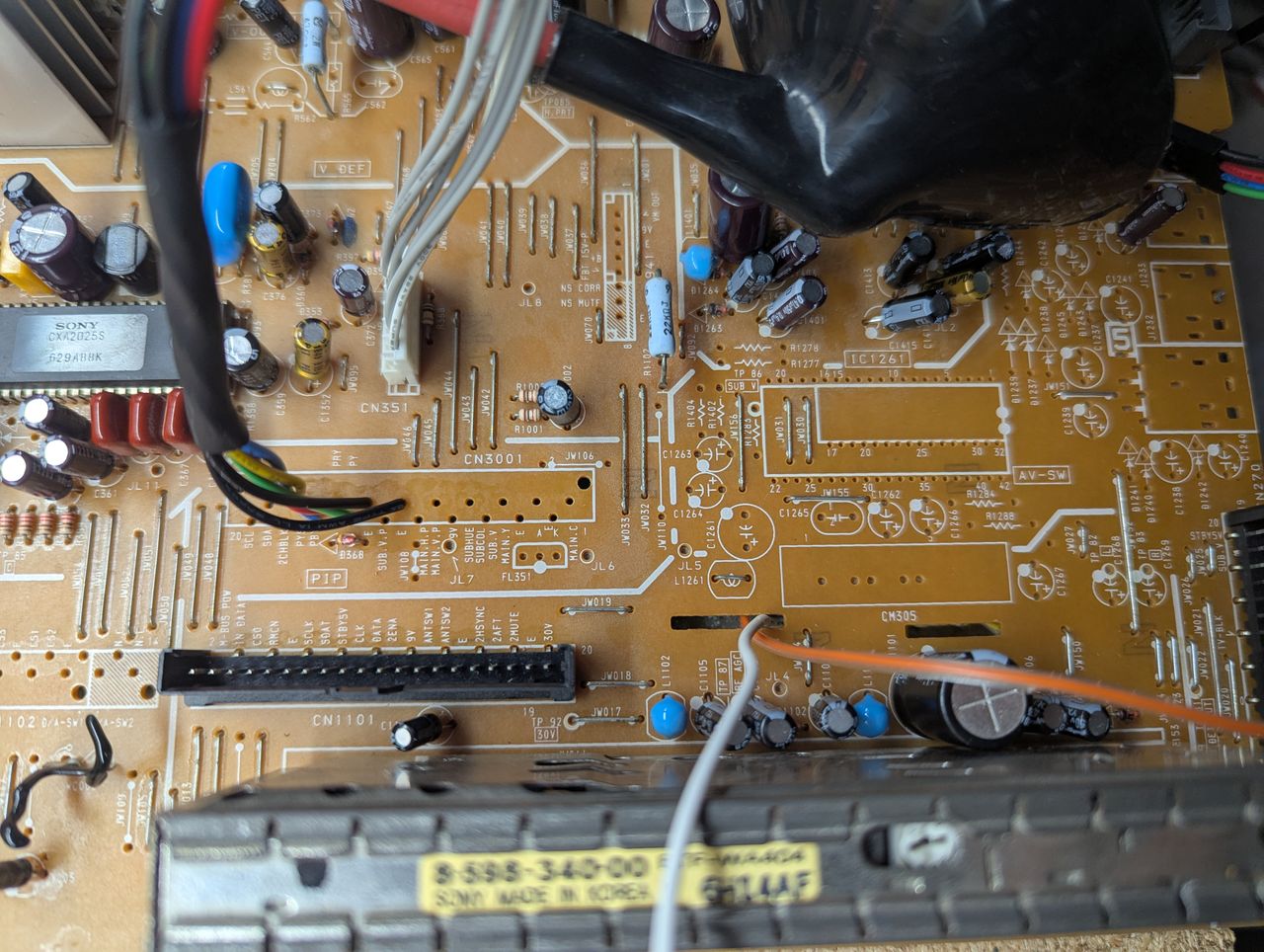
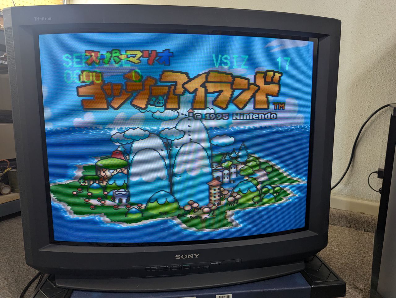
The Sony KV-32V35 is a 32" curved CRT television released in the late 1990s as part of Sony’s respected Trinitron line. It features an aperture grille picture tube that delivers bright, vibrant colors. The television includes RF, Composite, and S-Video ports, but it lacks Component/YPbPr and RGB inputs. For audio, it has built-in stereo speakers with SRS (Sound Retrieval System) and WOW True Surround audio processing.
View full CRT details and more mod examples →
Contributors
Thank you to everyone who contributed to this guide:
- Bradley Bowman — showcase author
- Sean Burke — contributor, RGB mod pictures
CRT safety
Caution
You can die doing this! So read carefully! CRT TV is not a toy. Do not open a CRT TV. If you don't have any prior knowledge about handling high voltage devices, this guide is not for you. CRT TV contains high enough voltage (20,000+ V) and current to be deadly, even when it is turned off.
Plan of attack
Manuals and Datasheets
No manuals or datasheets available yet.
Specs
- Year: 1997
- Format: NTSC
- Chassis: AA-2
- Tube: A68KZJ50X
- Jungle Chip: Sony CXA2025AS
- OSD Chip: CXP8564D-004S
- Screen Size: 27"
- Weight: 89.5 lbs
- Inputs: Composite, RF
RGB mux diagram
Prepare the mux diagram. If you are building your own circuit, this diagram should help.
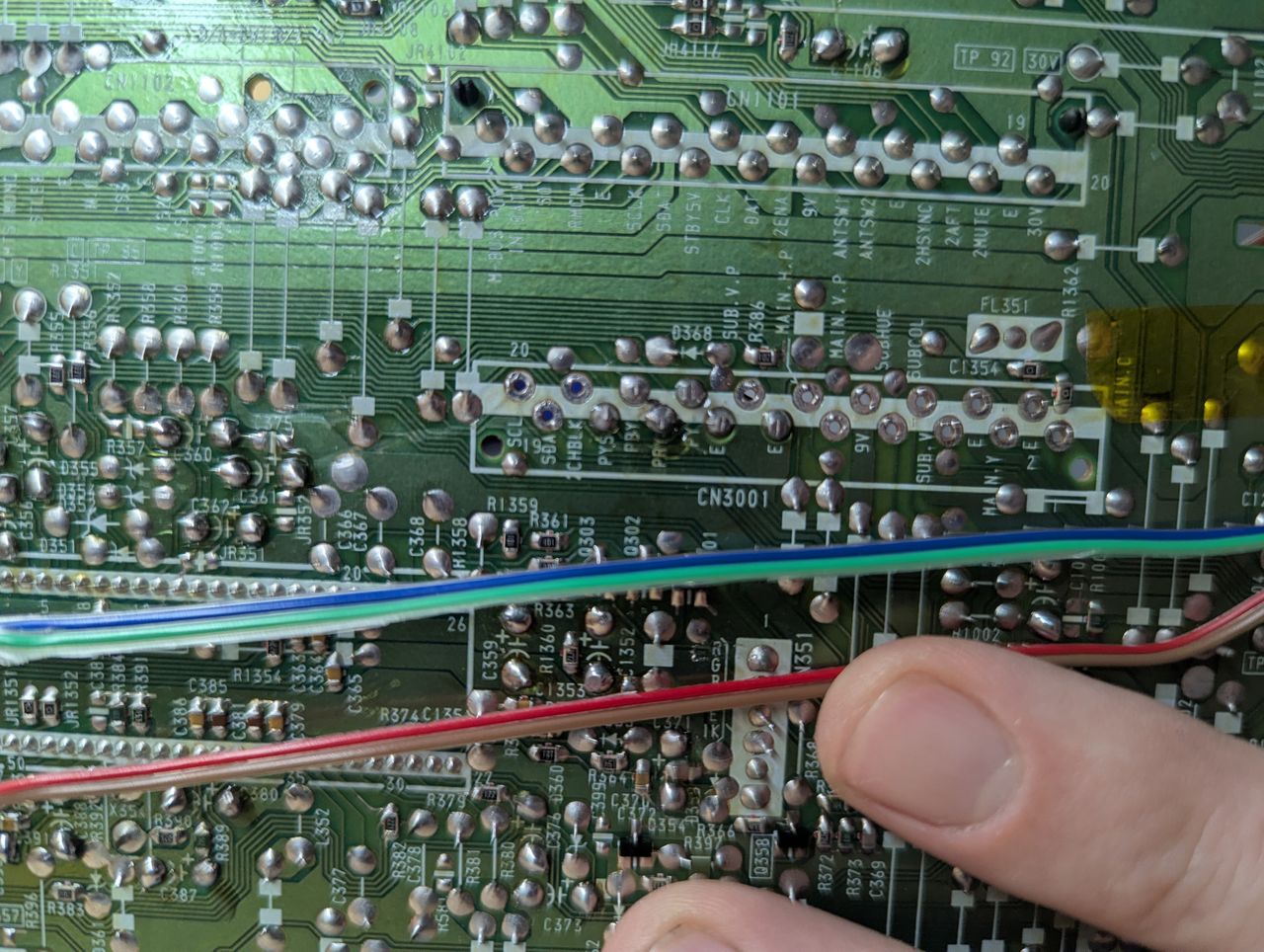
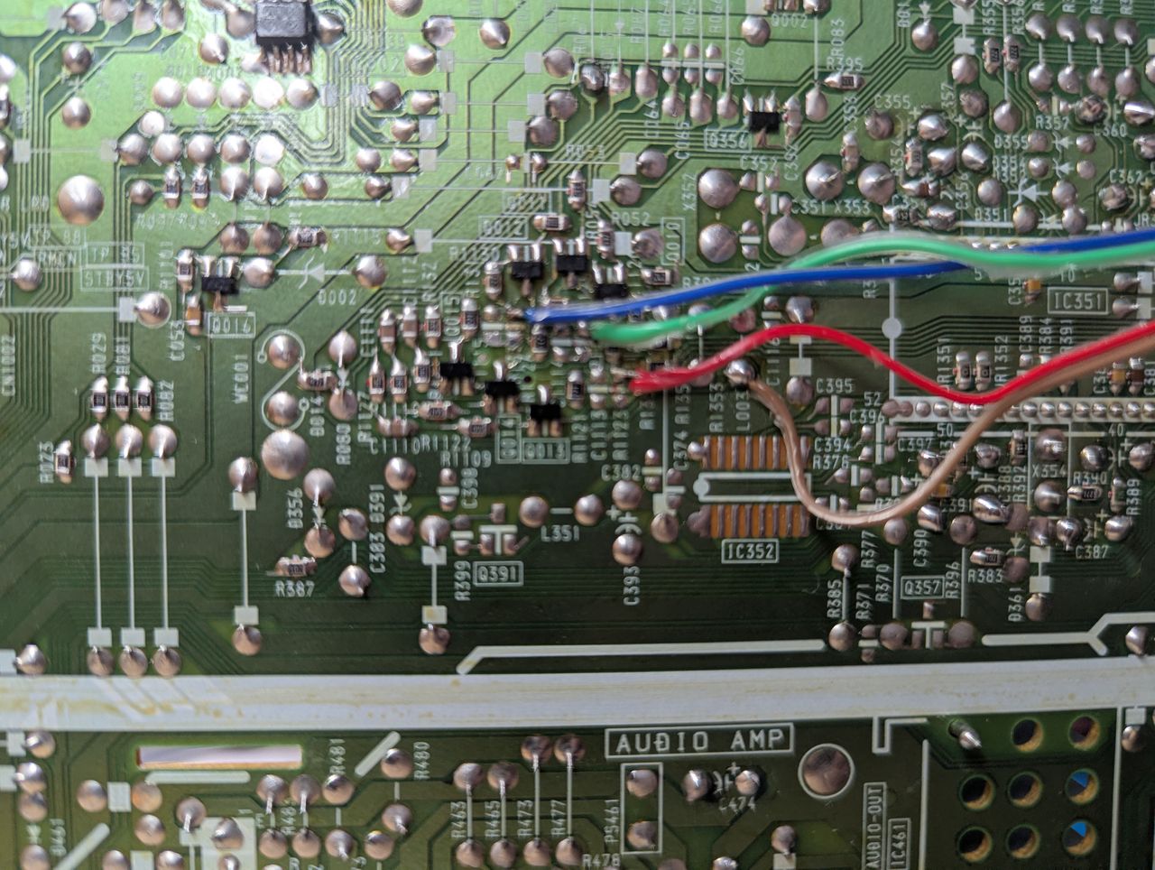
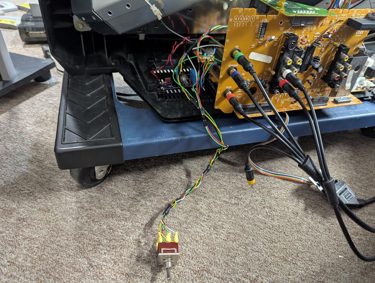
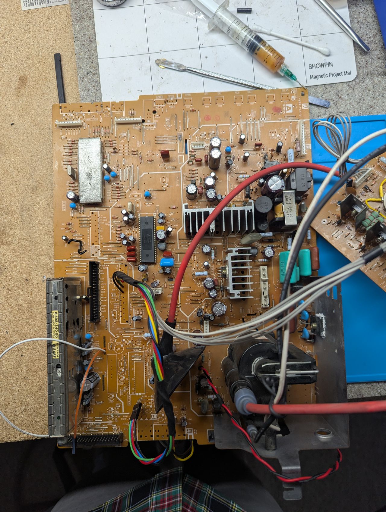
Performing the mod
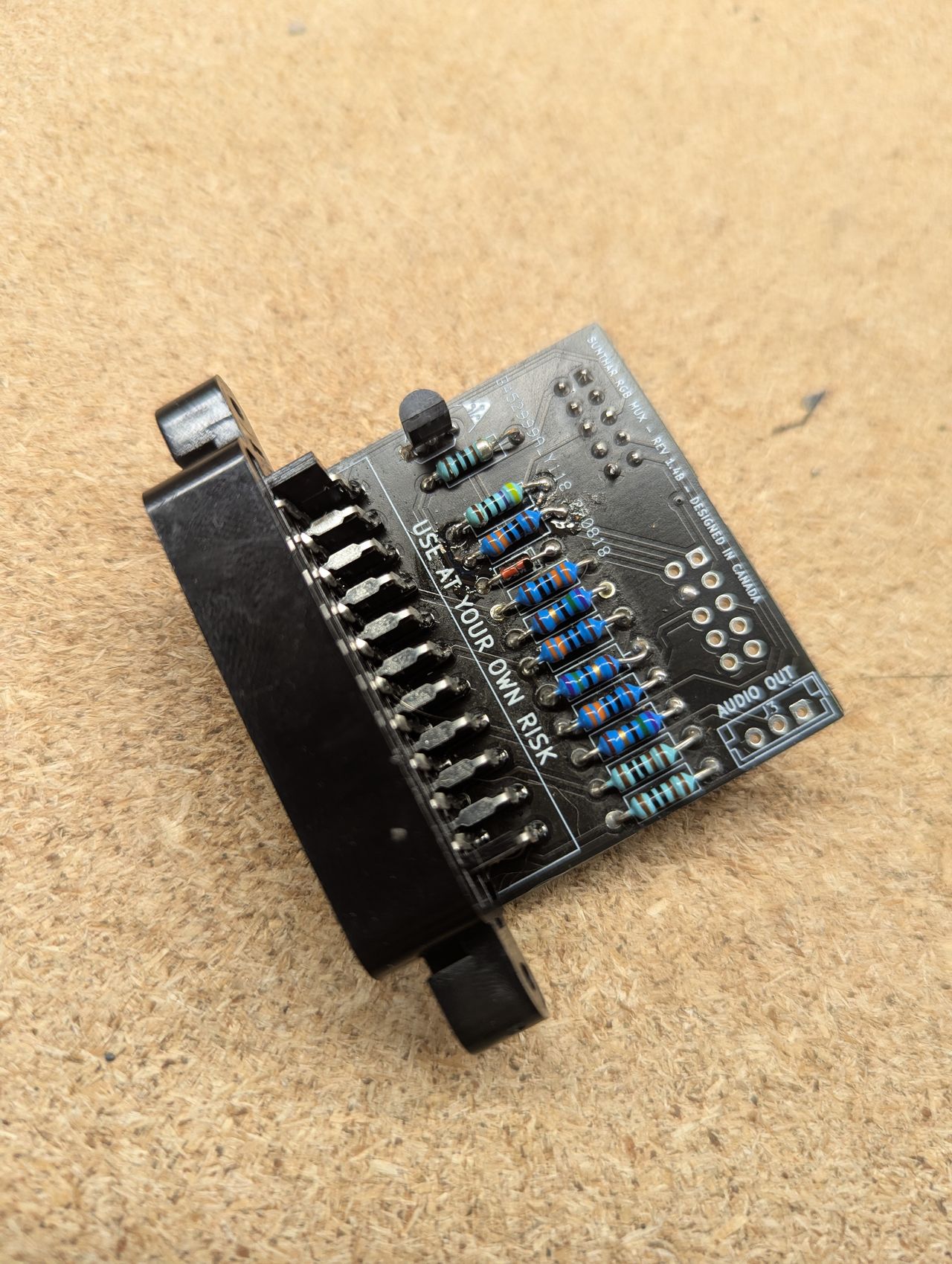
This mod uses the RGB mux board. This is optional, but will make your mod easier and stable. You can also create the circuit presented in the schematics above without the board. Please also checkout the mux calculator to play with your own values.
| On Sony CRT Chassis | KV-32V35 |
|---|---|
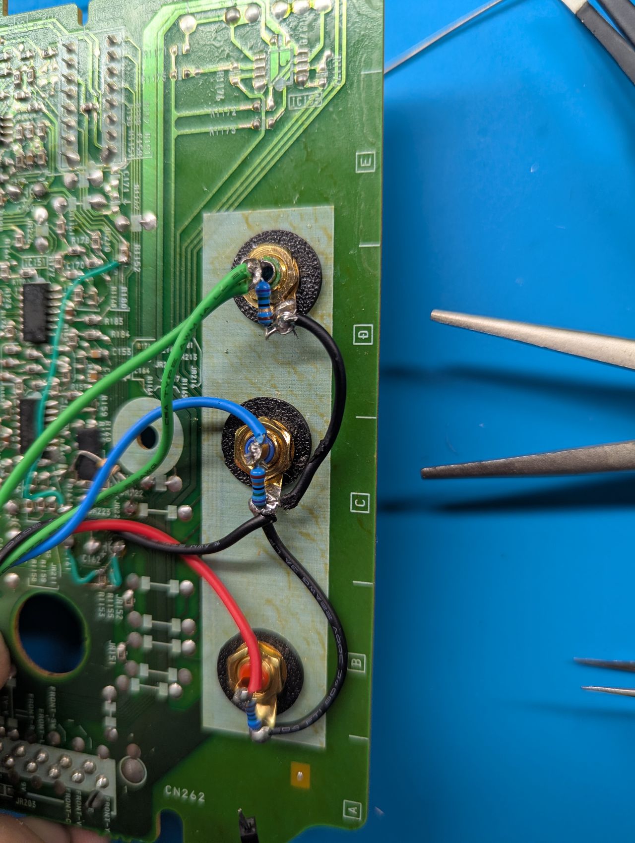
| CRT RGB inline resistor | 2.2kΩ |
| CRT RGB ground resistors removed | 390Ω |
| 0.1μF caps replaced | No |
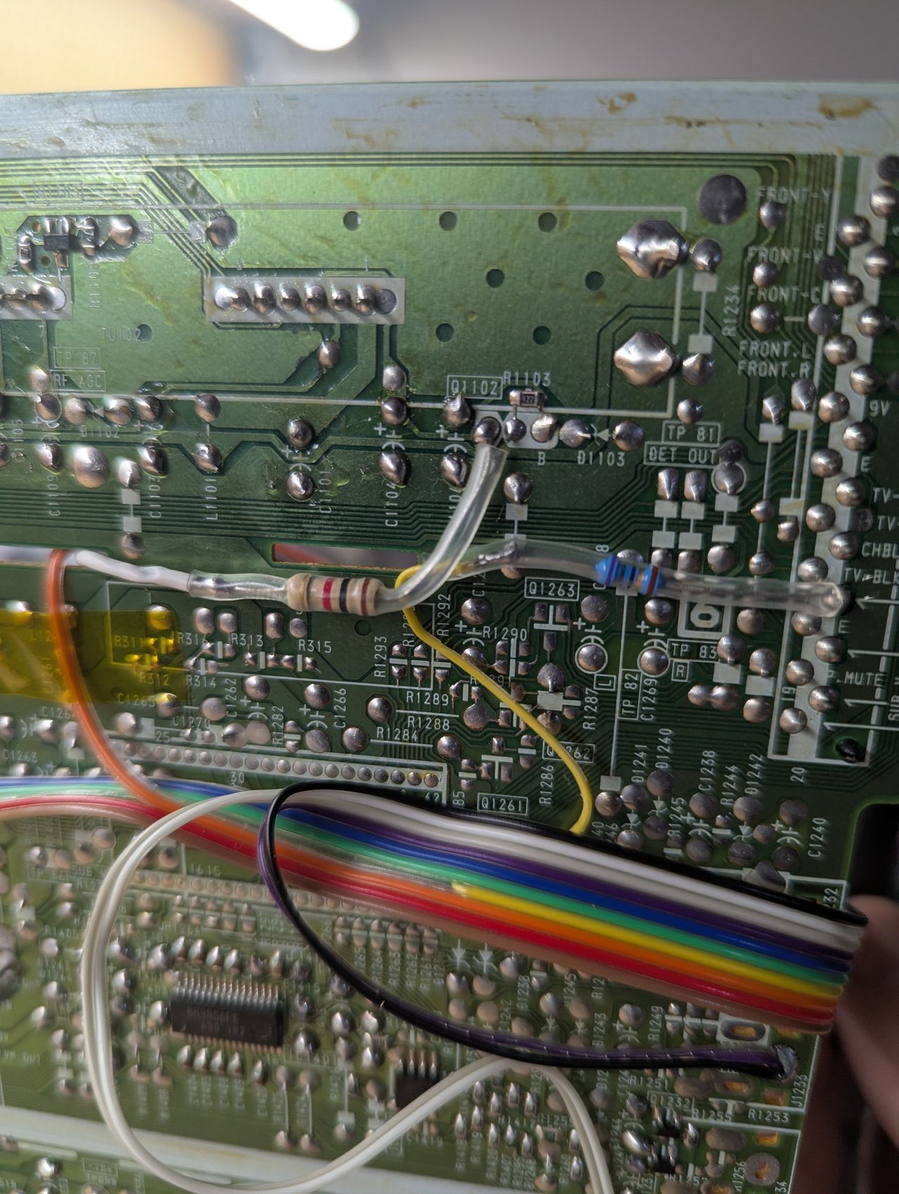
| Add diodes on chassis RGB lines? | No |
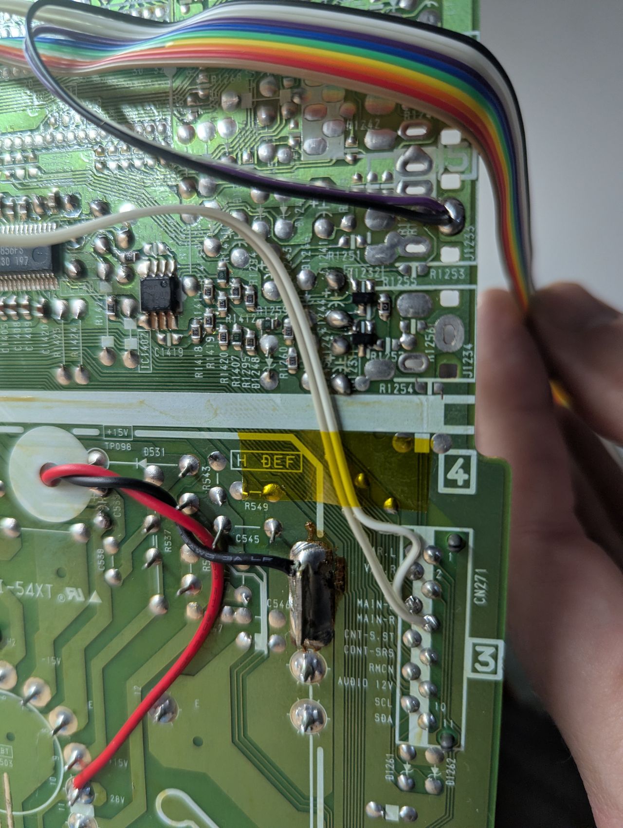
| Add blanking diode on chassis | Yes |
| RGB mux board | KV-32V35 |
|---|---|
| Mux board RGB termination (R1, R2, R3) | 75Ω |
| Mux board RGB inline resistors (R4, R5, R6) | 330Ω |
| Mux board Audio LR (R7, R8) | 1kΩ |
| Mux board blanking diode (R9) | 1N4148 |
| Mux board blanking ground resistor (R10) | 330Ω |
| Mux board blanking resistor (R11) | 470Ω |
| Mux board transistor base resistor (R12) | 1kΩ |
| Mux board transistor (Q1) | PN2222A |
Compatible mux boards:
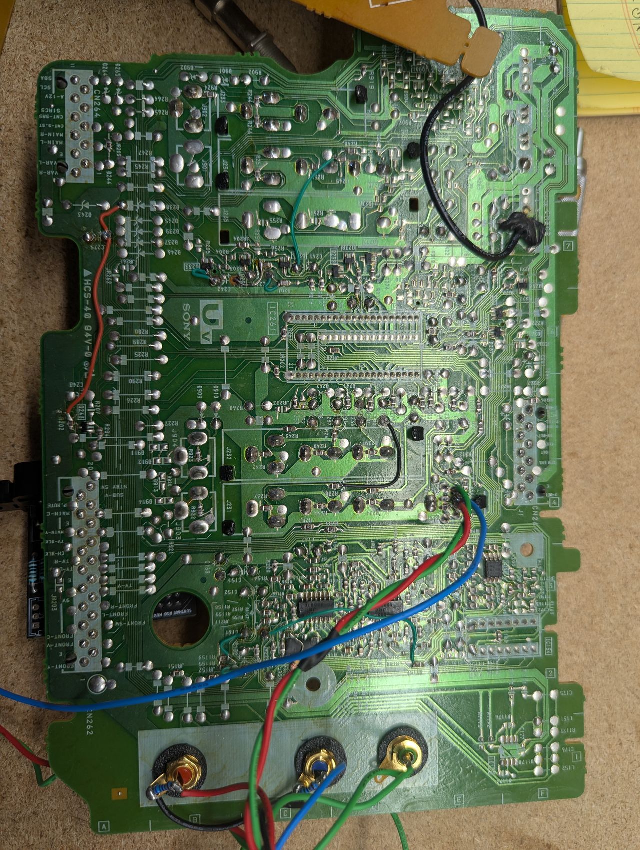
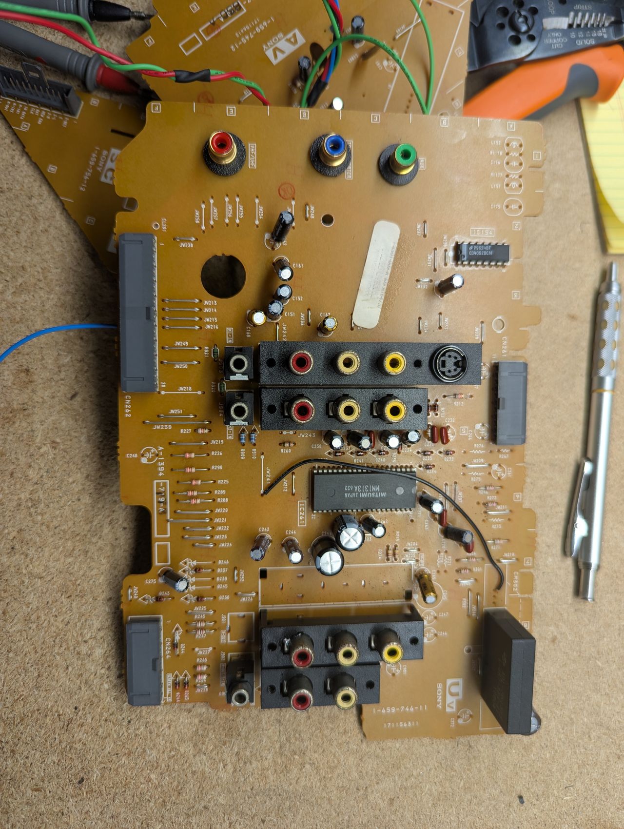
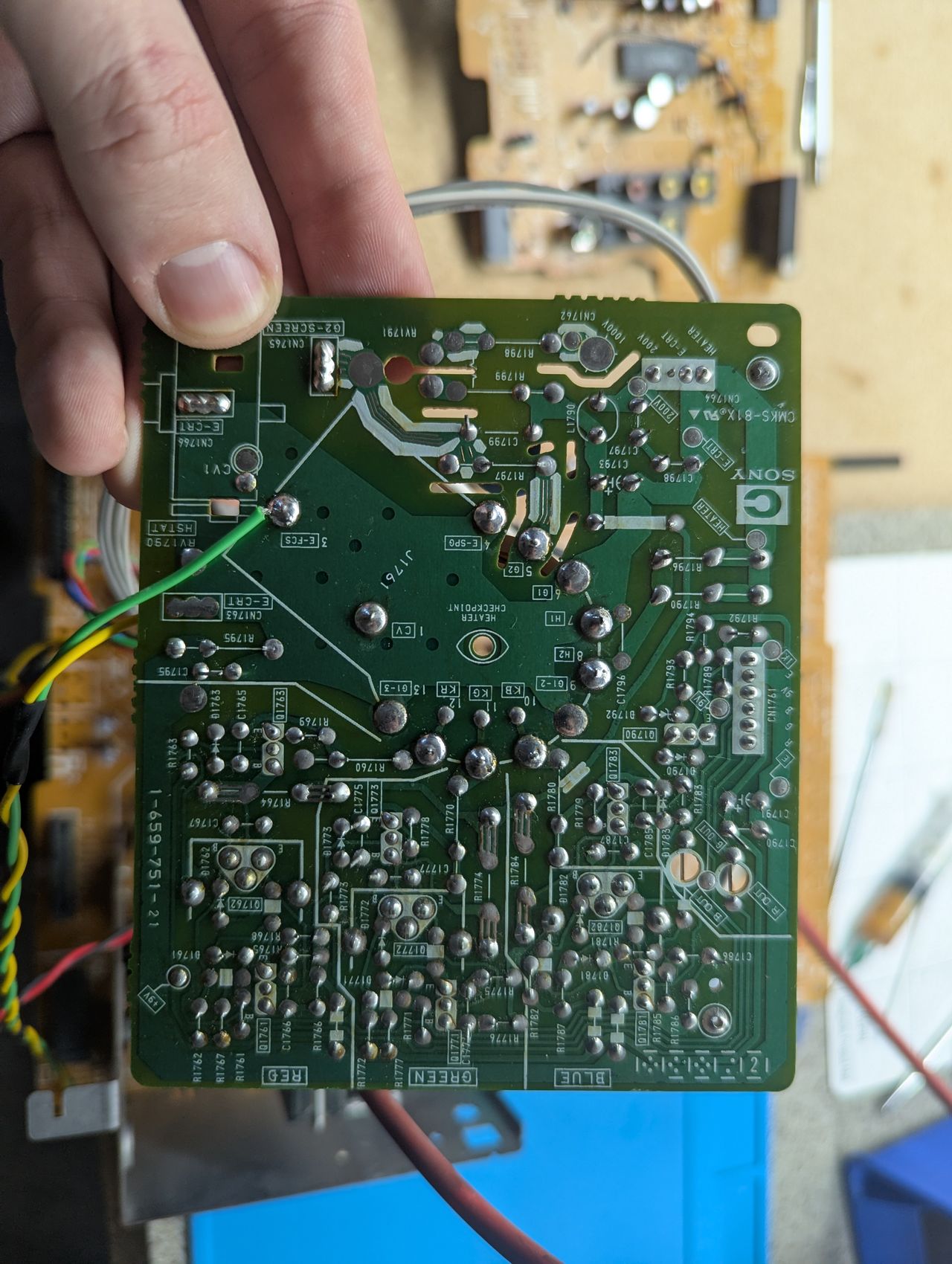
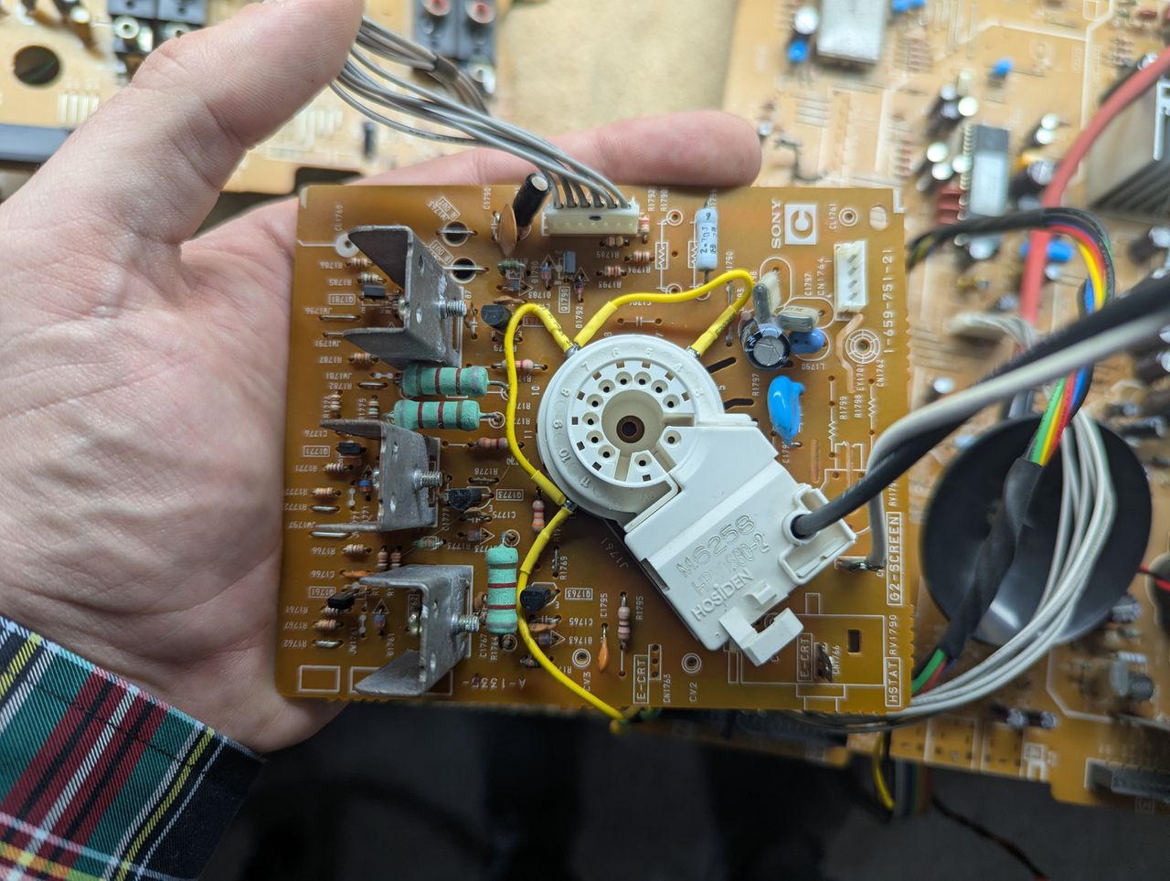
Pictures
Photos by Bradley Bowman