Sony (AA-1) KV-27TS36
Sony (AA-1) KV-27TS36 CRT RGB mod
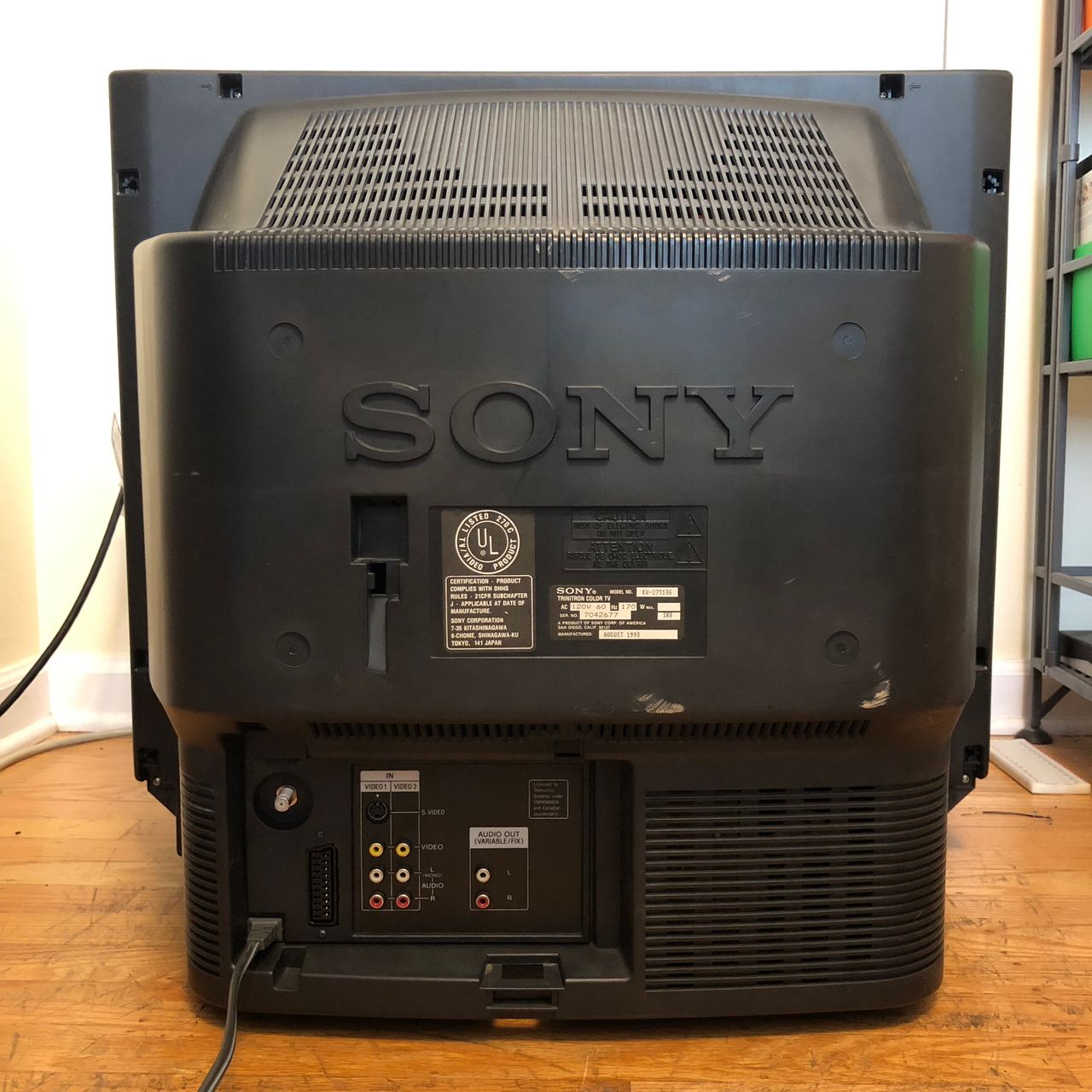
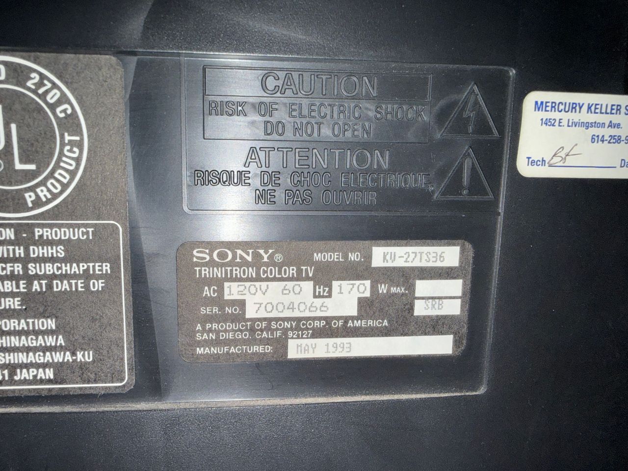
The Sony KV-27TS36 is a 27" curved Trinitron CRT television released in 1993. It features excellent built-in stereo speakers, and is part of Sony's reliable AA-1 chassis.
This set is RGB moddable using the direct injection method.
View full CRT details and more mod examples →
Contributors
Thank you to everyone who contributed to this guide:
- Eli Krause — contributor, CRT specs from CRT Database.
- Kaz Packman — contributor, RGB mod and pictures
CRT safety
Caution
You can die doing this! So read carefully! CRT TV is not a toy. Do not open a CRT TV. If you don't have any prior knowledge about handling high voltage devices, this guide is not for you. CRT TV contains high enough voltage (20,000+ V) and current to be deadly, even when it is turned off.
Plan of attack
Manuals and Datasheets
- Sony KV-27TS36 Service Manual — Available for Pro Users only. See CRT details for access.
Specs
- Manufactured: Mexico (1993)
- Format: NTSC
- Chassis: AA-1
- Tube: Sony Trinitron A68KZJ50X
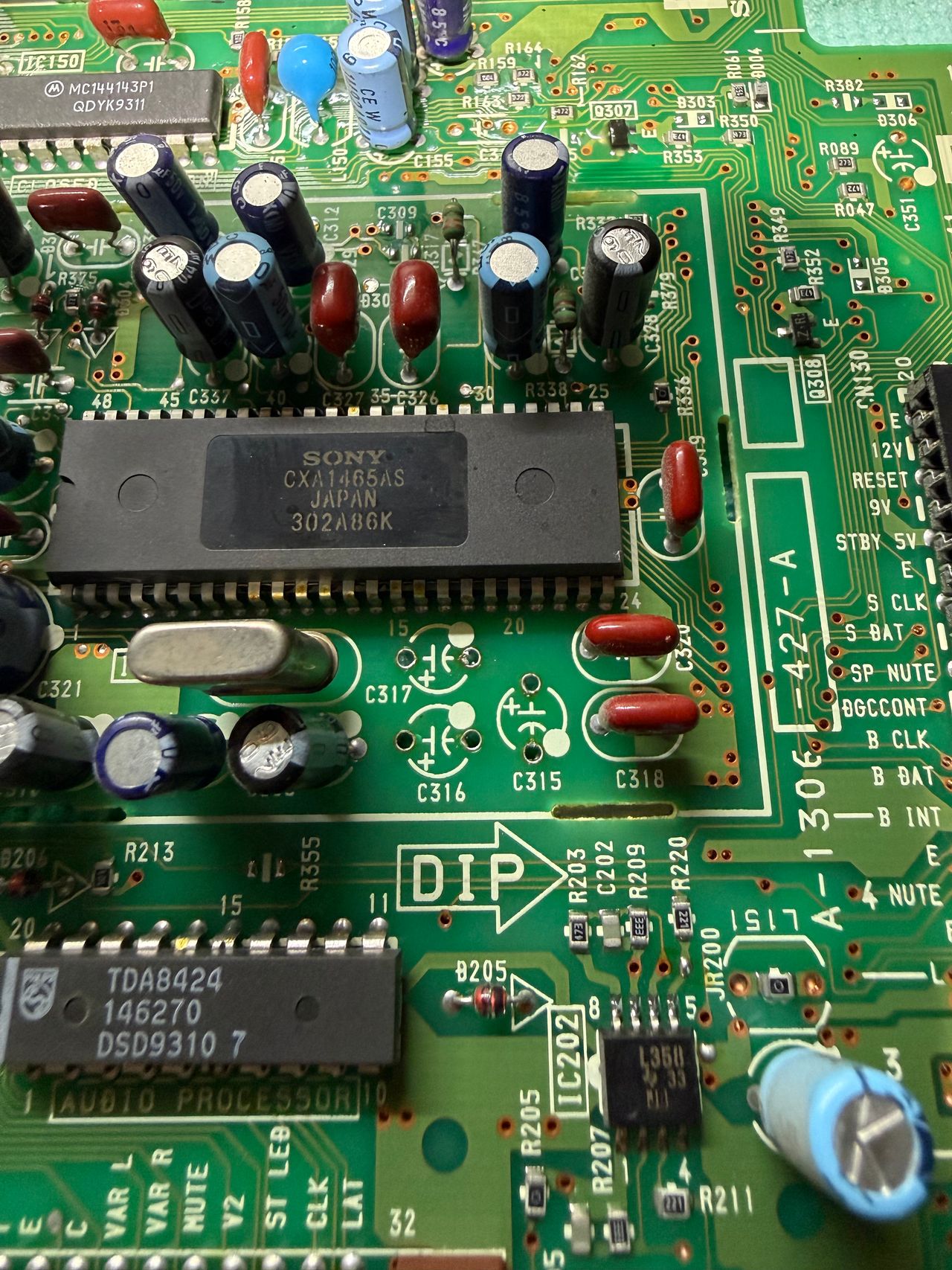
- Jungle Chip: Sony CXA1465AS
- Screen Size: 27"
- Weight: 93 lbs
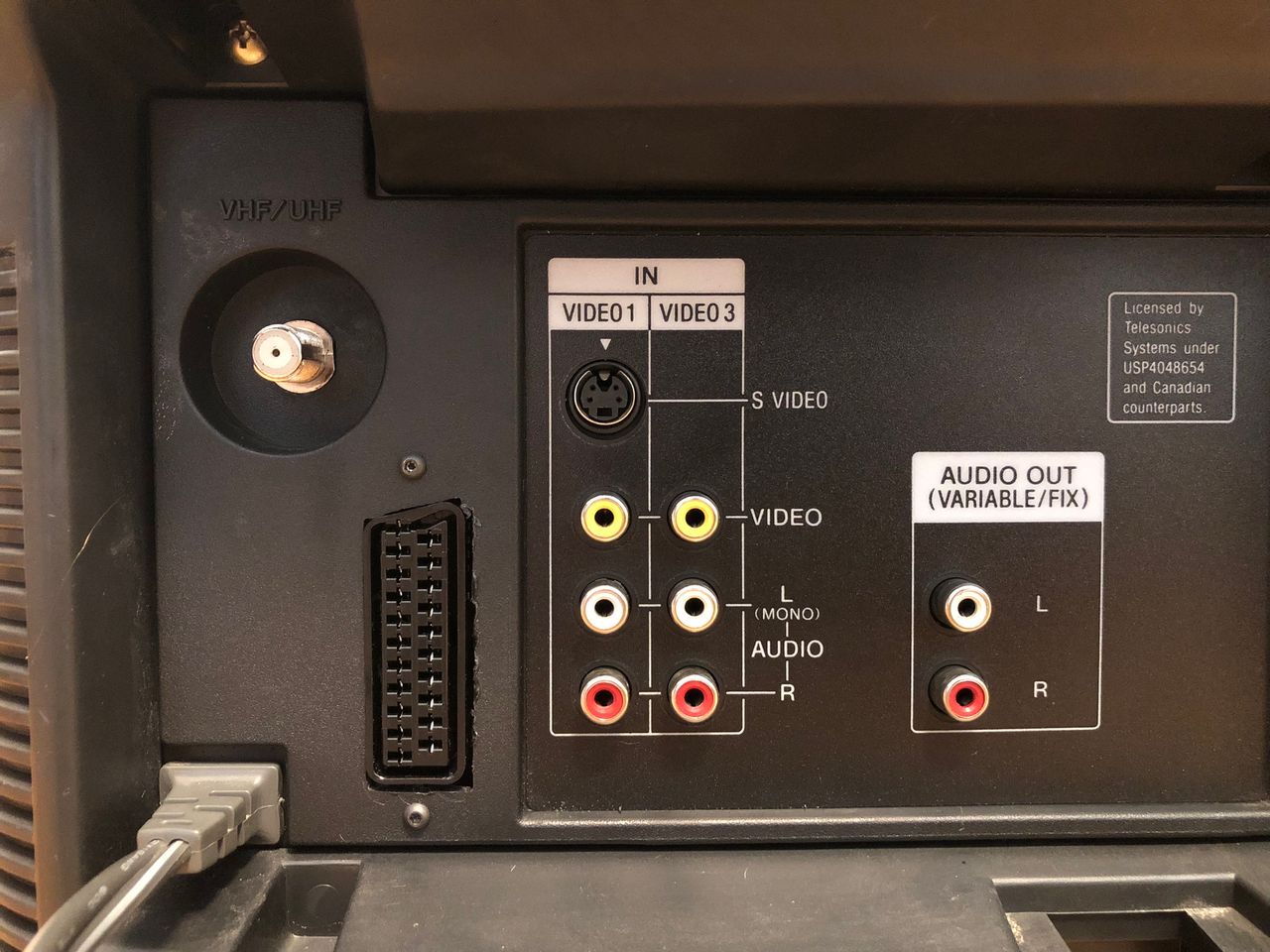
- Inputs: Composite, S-Video, RF
RGB mux diagram
Prepare the mux diagram. If you are building your own circuit, this diagram should help.
Schematics
Really simple RGB mod is possible on this chassis. We will be disabling Closed Caption Decoder (CCD) and leveraging the analog RGB inputs used to feed our external RGB signal.
Let's review the block diagram and schematics first.
Chroma CXA1465AS - Block Diagram 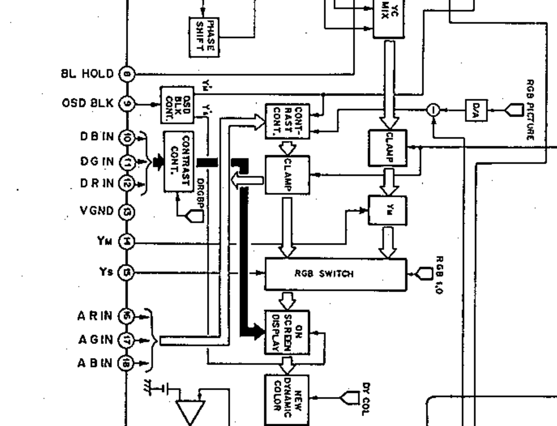
If you look at the block diagram, analog R, G, B inputs at pins 16, 17, 18 are what we are going to be harnessing.
Chroma CXA1465AS - Schematics 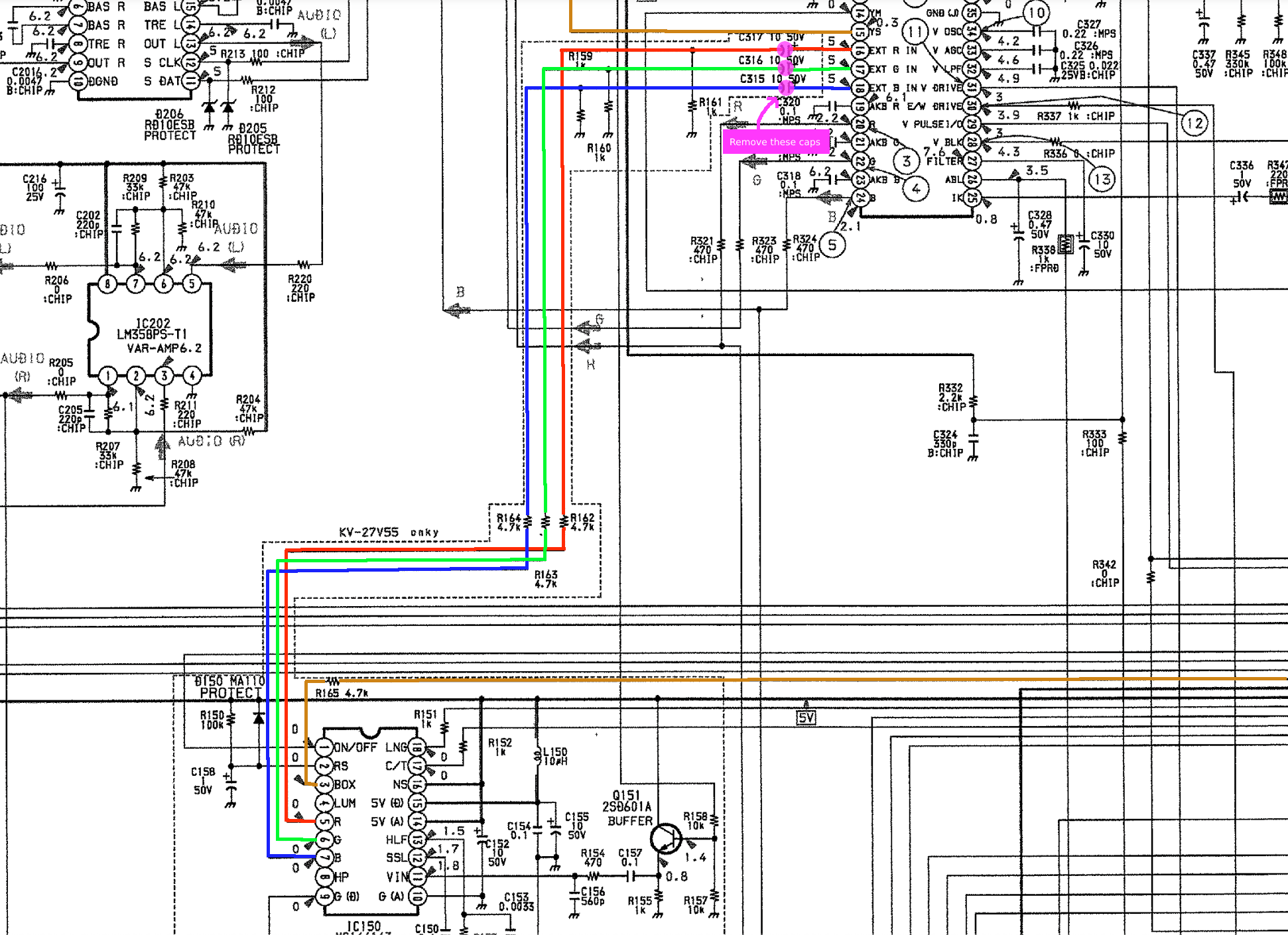
The above schematics shows the R, G, B, Blanking signal going from the CCD chip to the CXA1465AS chip. Pink circle shows the caps C315, C316 and C317 that we will be removing.
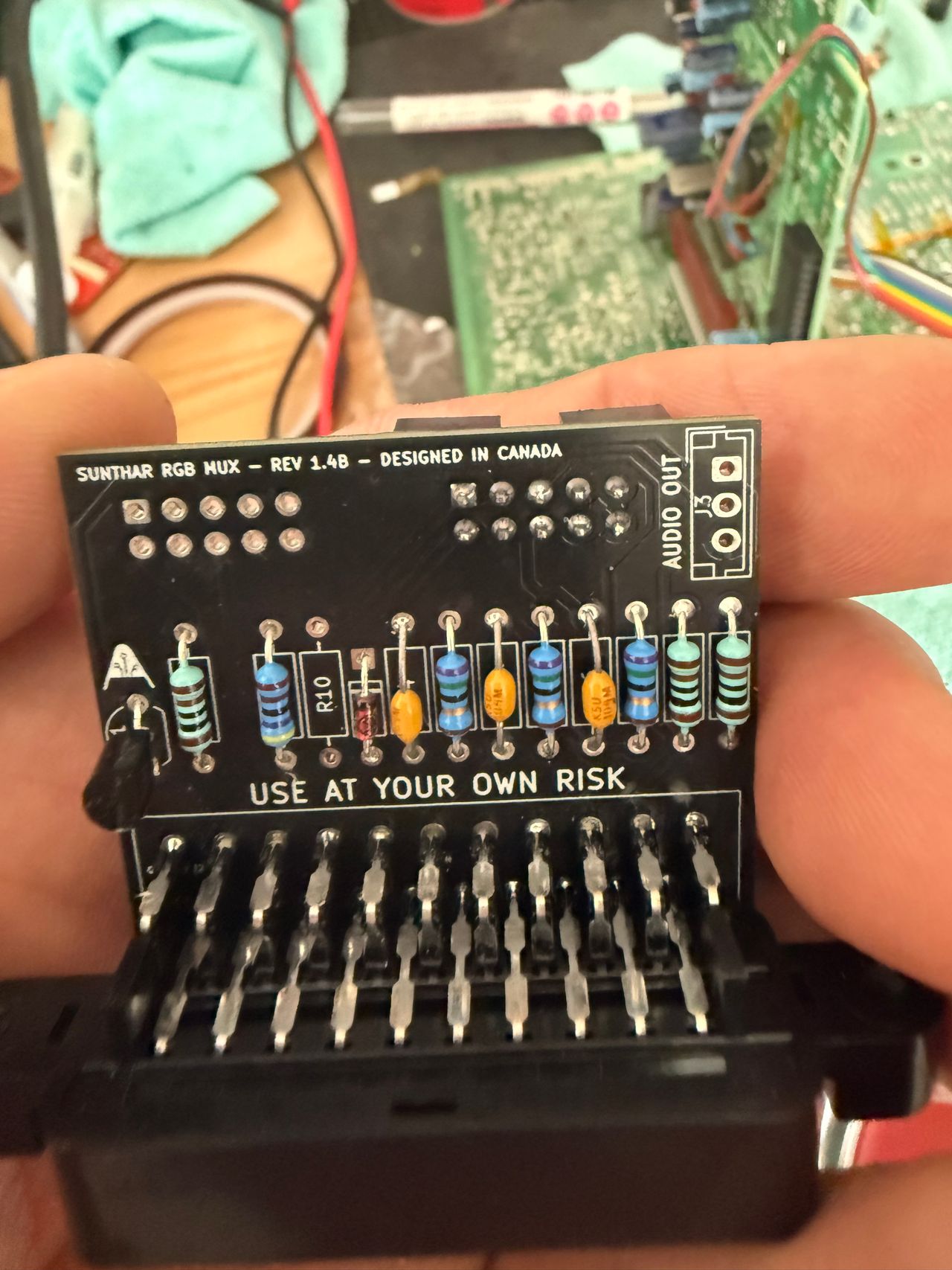
This mod uses the RGB mux board. This is optional, but will make your mod easier and stable. You can also create the circuit presented in the schematics above without the board. Please also checkout the mux calculator to play with your own values.
| On Sony CRT Chassis | KV-27TS36 |
|---|---|
| 0.1μF caps replaced | No |
| Add diodes on chassis RGB lines? | No |
| Add blanking diode on chassis | No |
| RGB mux board | KV-27TS36 |
|---|---|
| Mux board RGB termination (R1, R2, R3) | 75Ω |
| Mux board RGB input capacitors (R4, R5, R6) | 0.1μF |
| Mux board Audio LR (R7, R8) | 1kΩ |
| Mux board blanking diode (R9) | 1N4148 |
| Mux board blanking ground resistor (R10) | open |
| Mux board blanking resistor (R11) | 4.7kΩ |
| Mux board transistor base resistor (R12) | 1kΩ |
| Mux board transistor (Q1) | PN2222A |
Compatible mux boards:
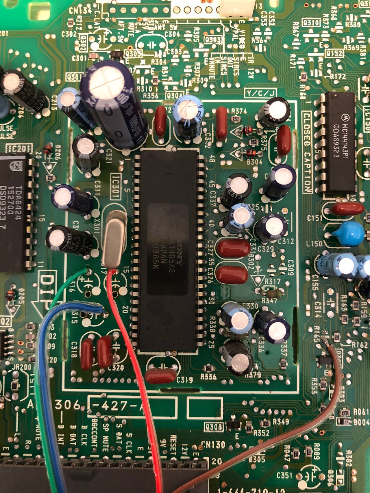
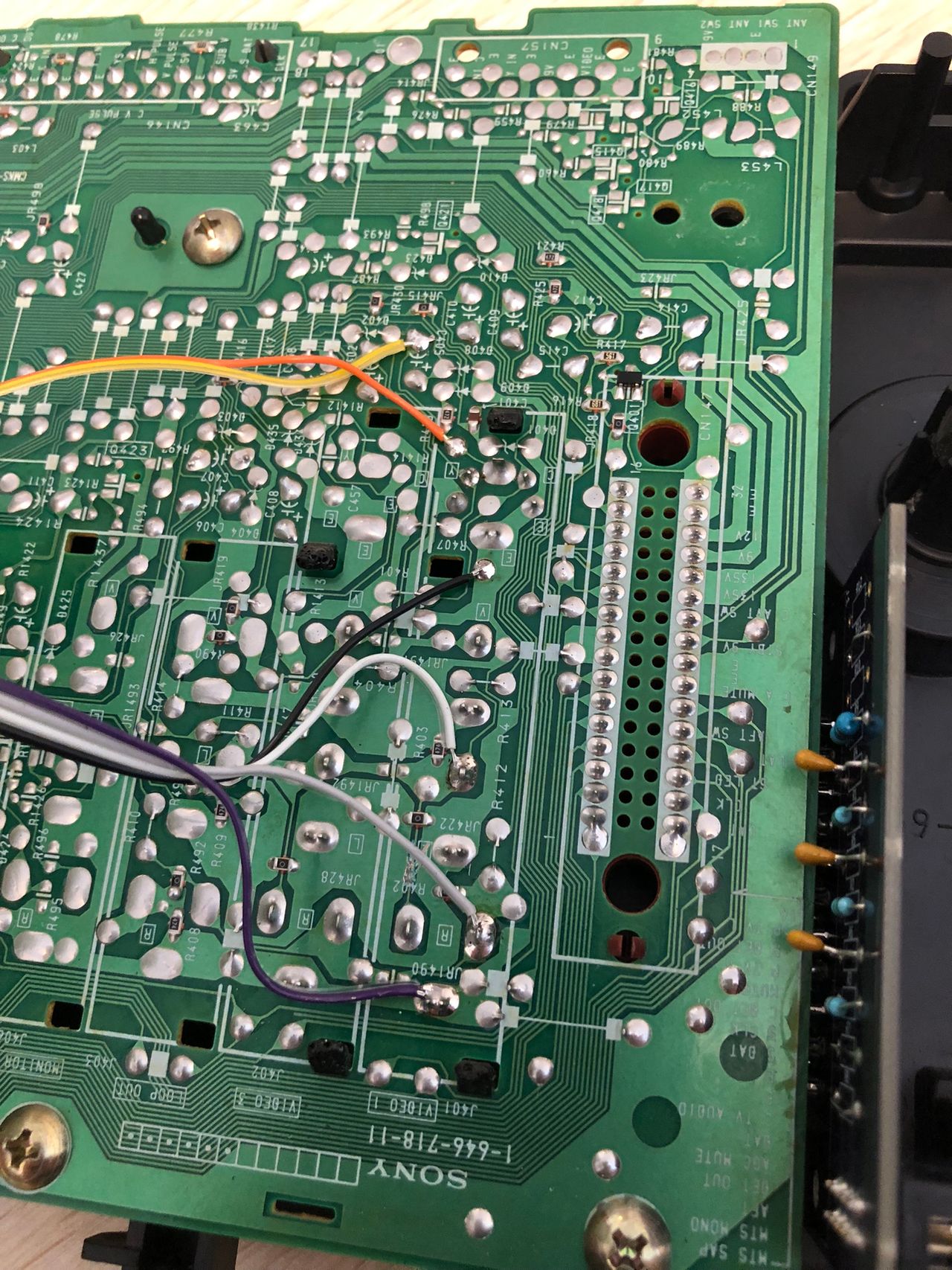
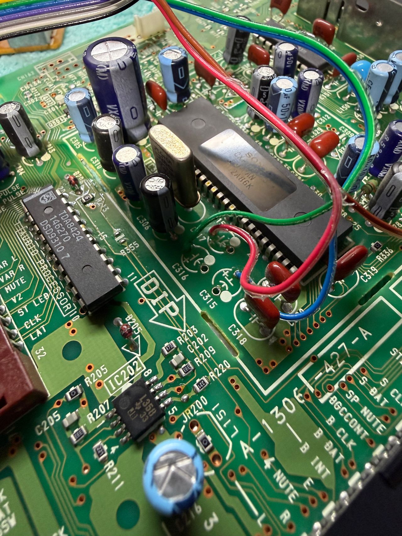
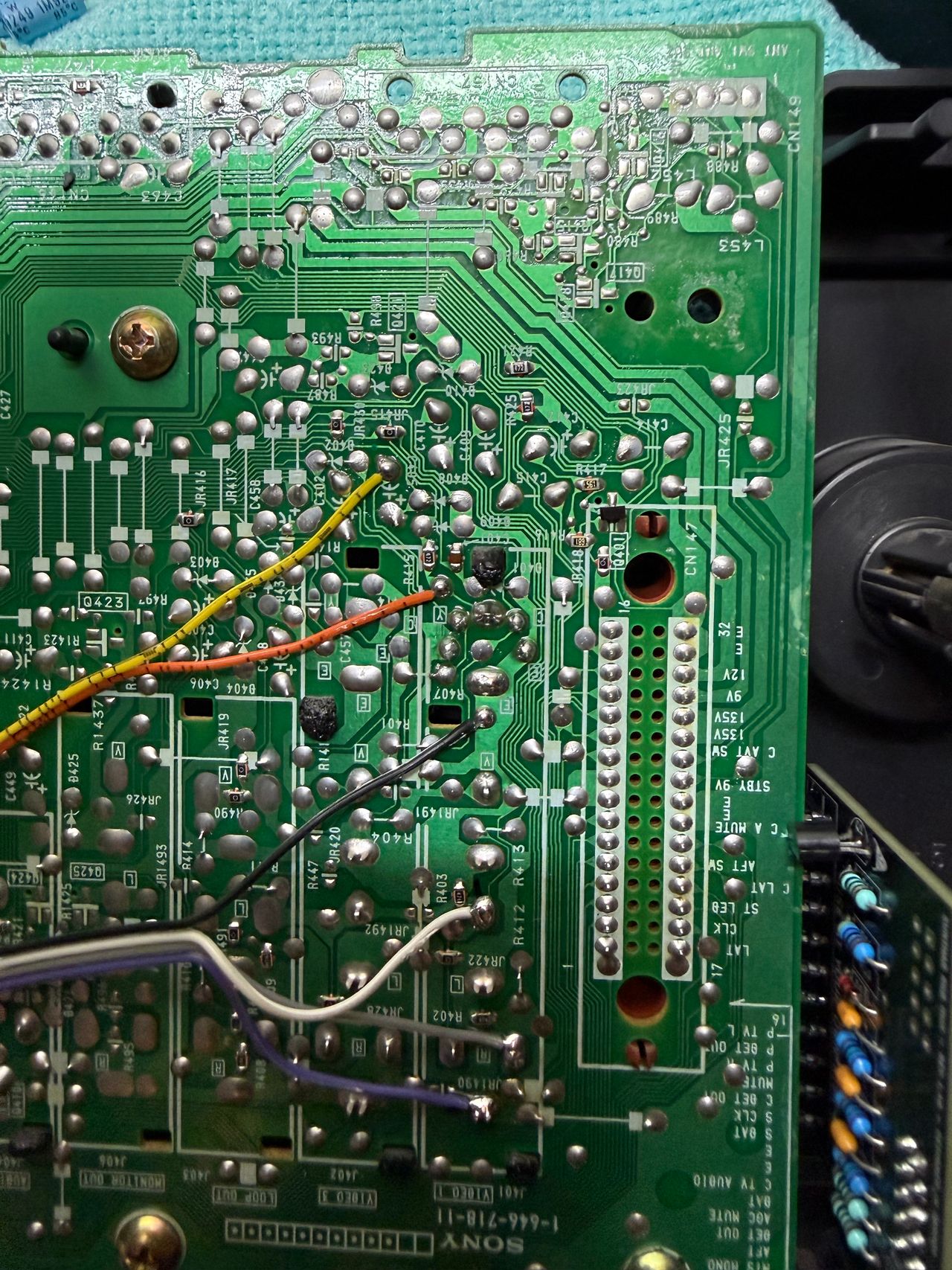
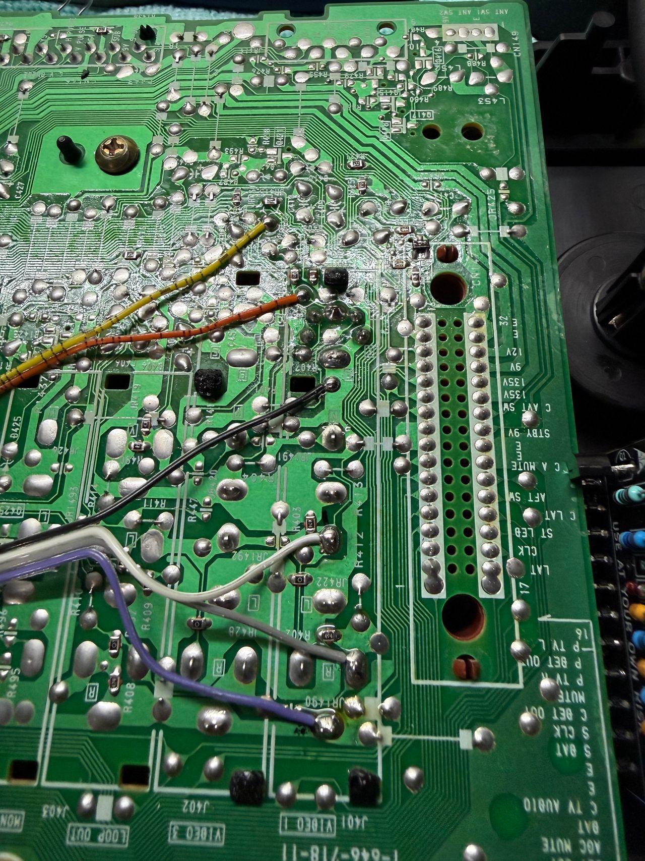
Performing the mod
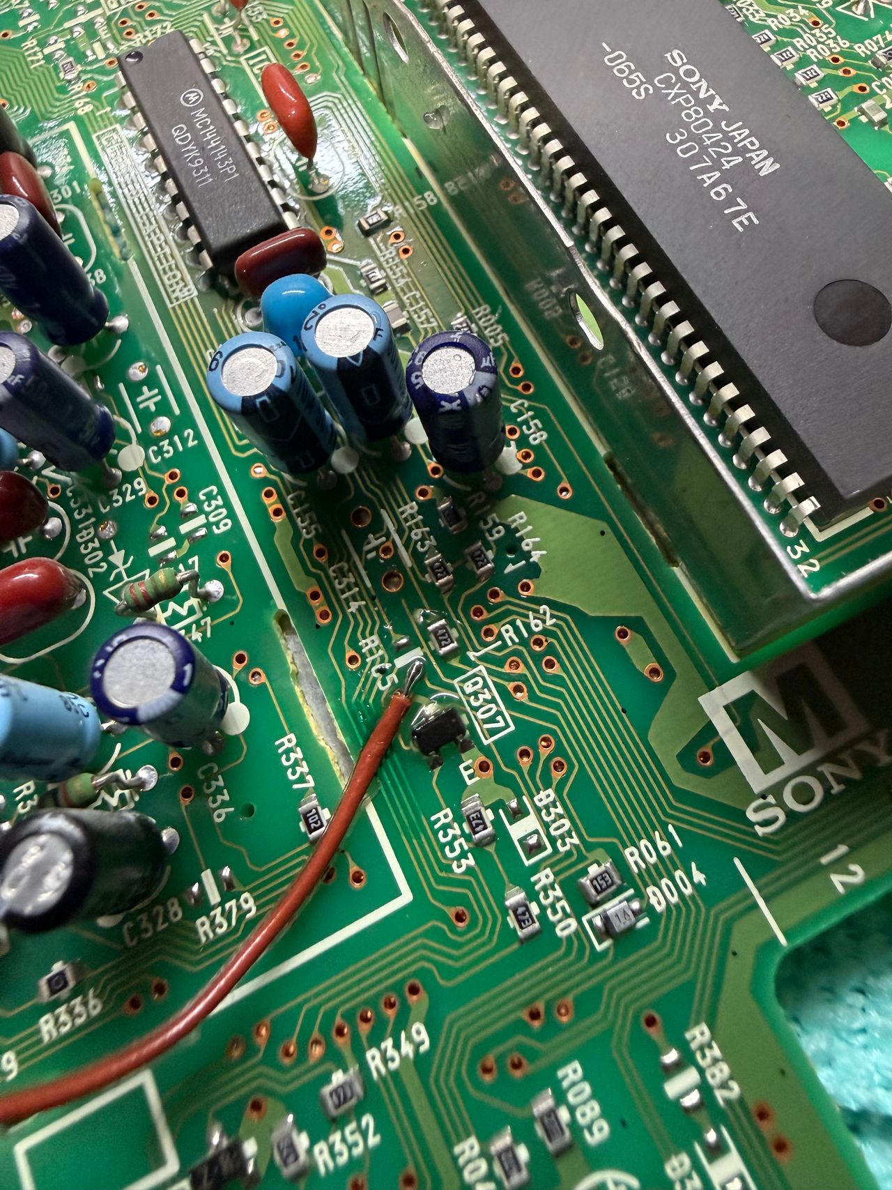
Remove capacitors C315, C316, C317 on the M board and inject R, G, B to the positive terminals. Isolate blanking by removing R165 and inject blanking there.
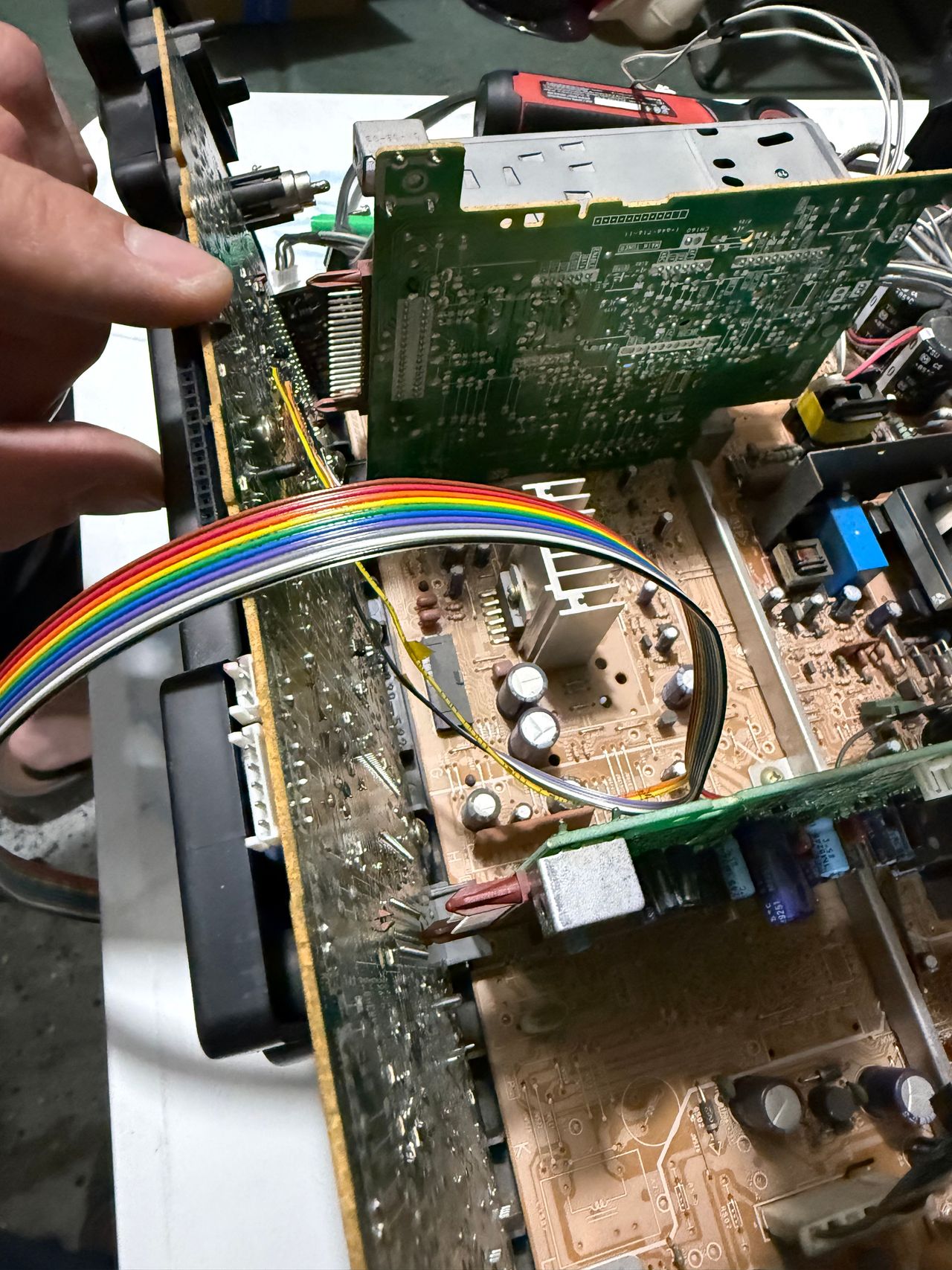
Pictures
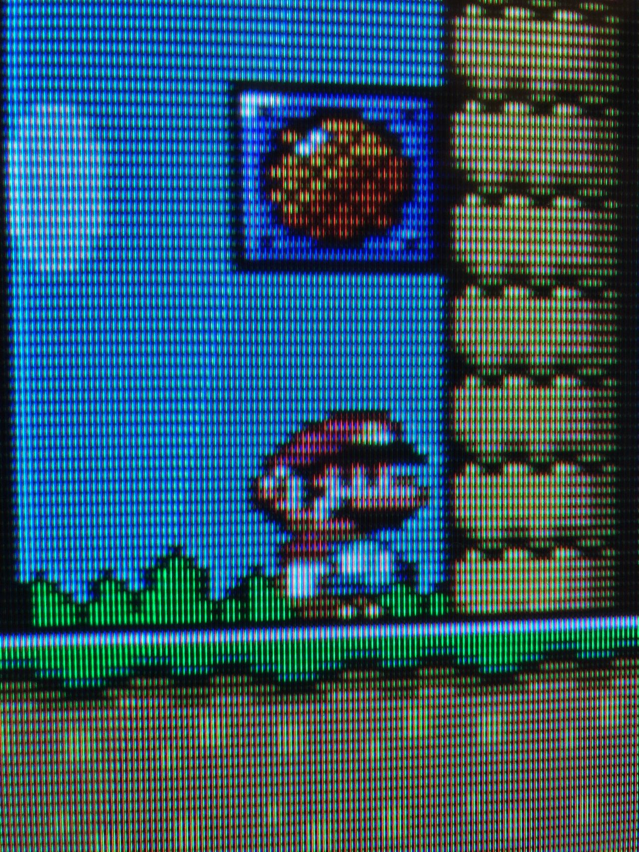
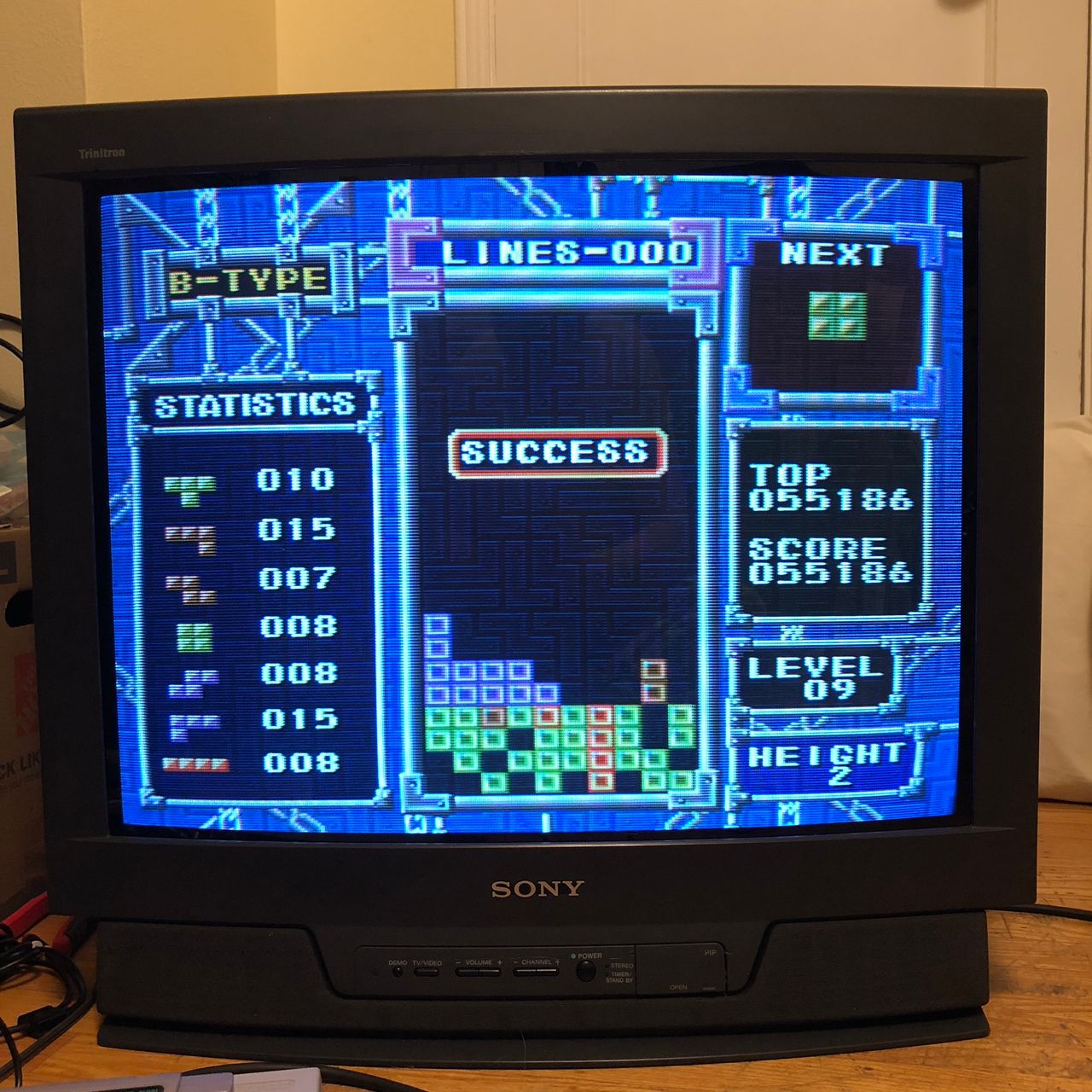
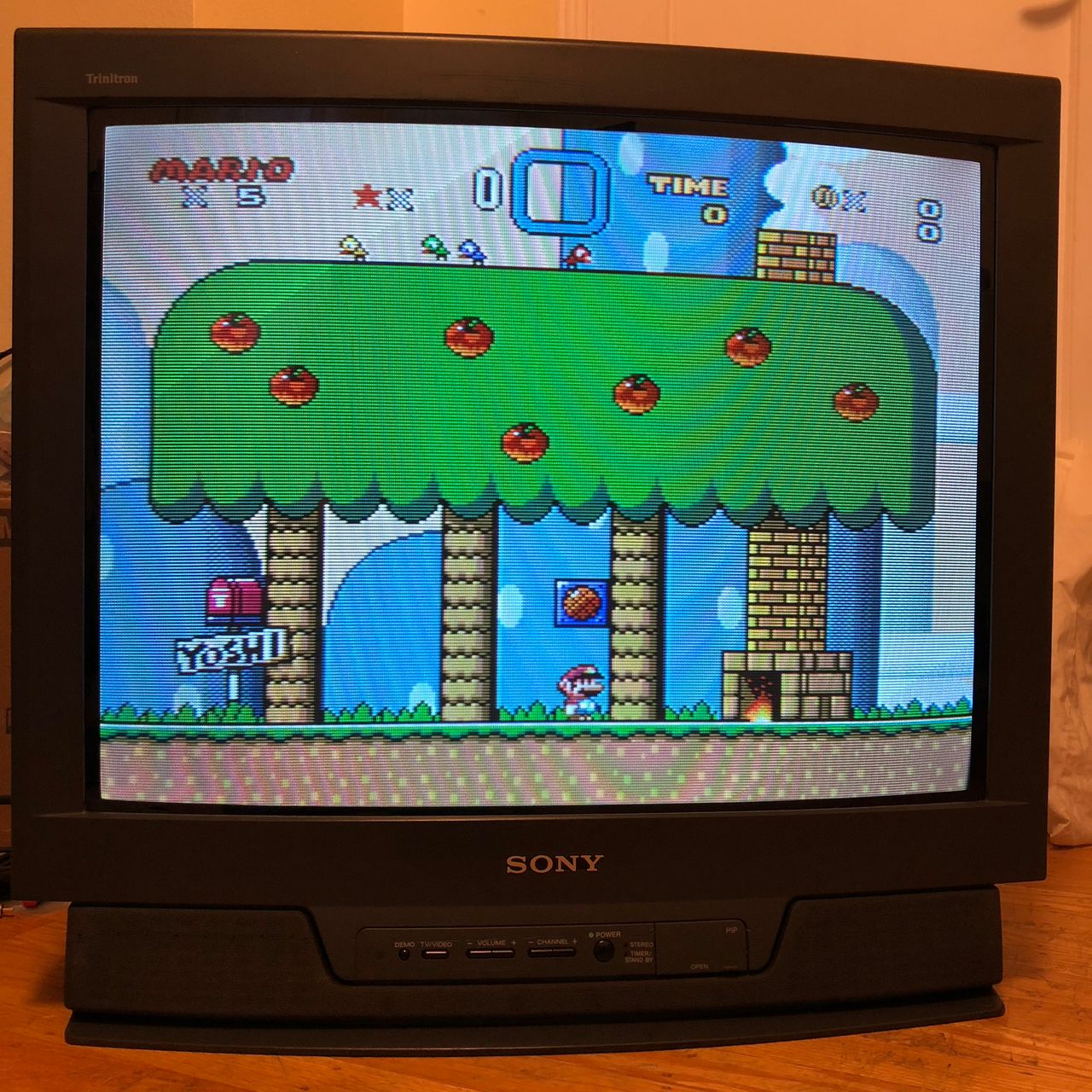
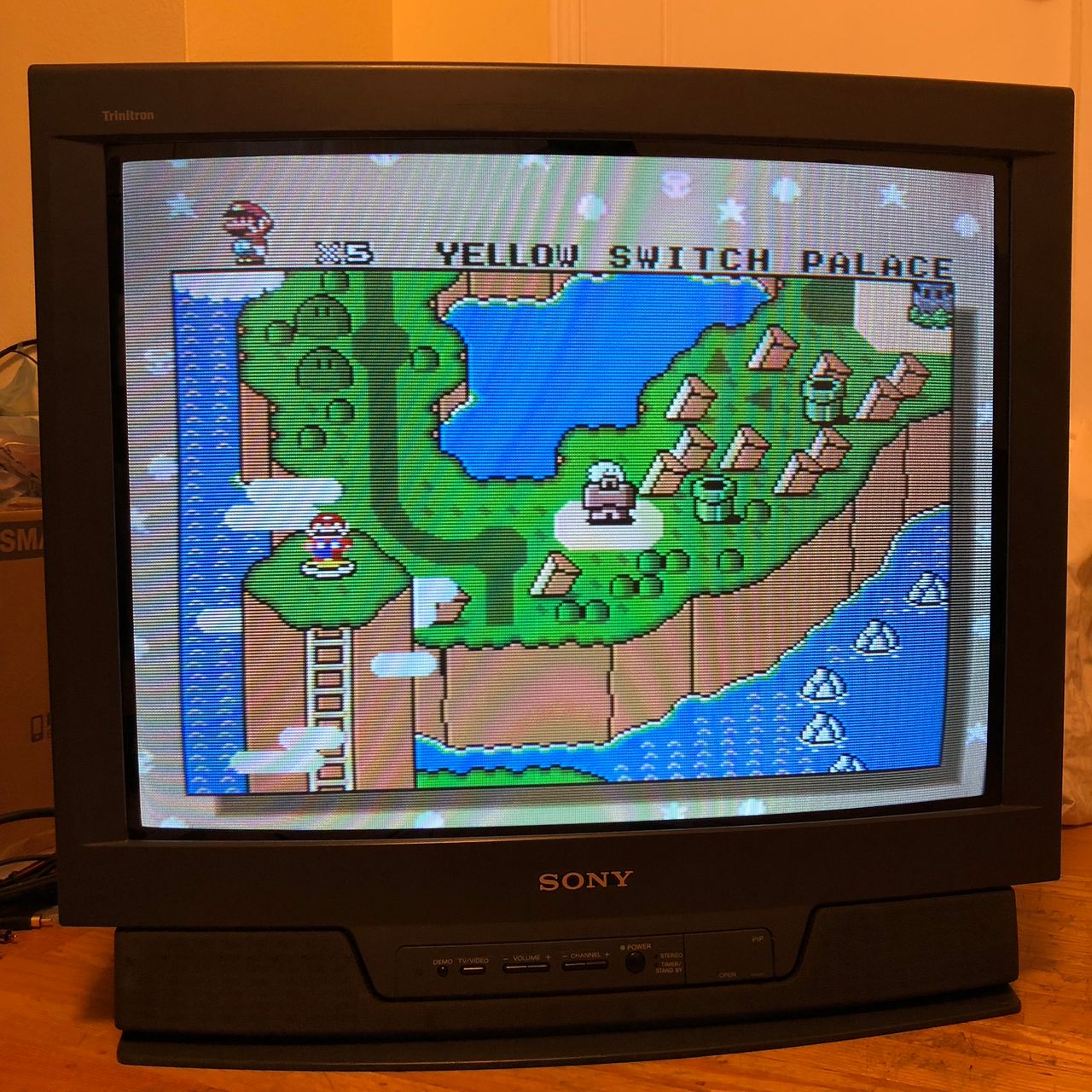
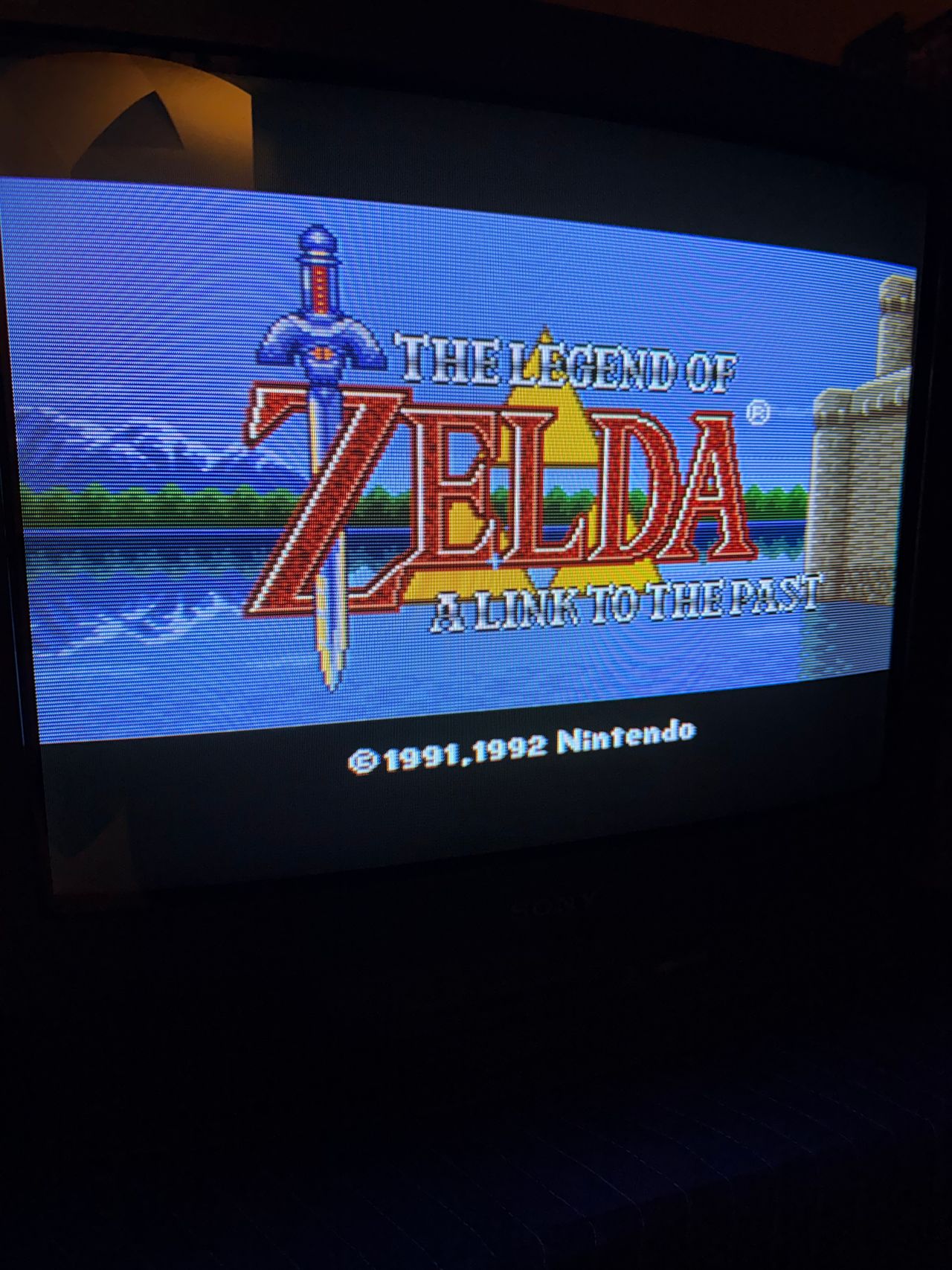
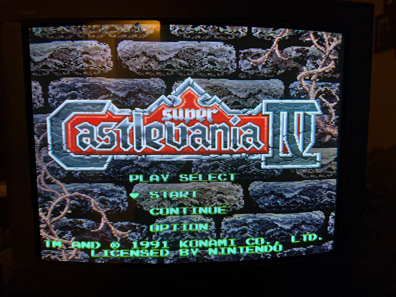
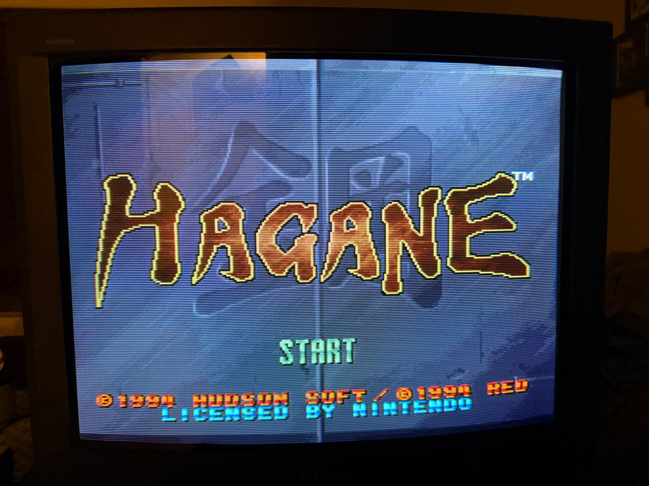
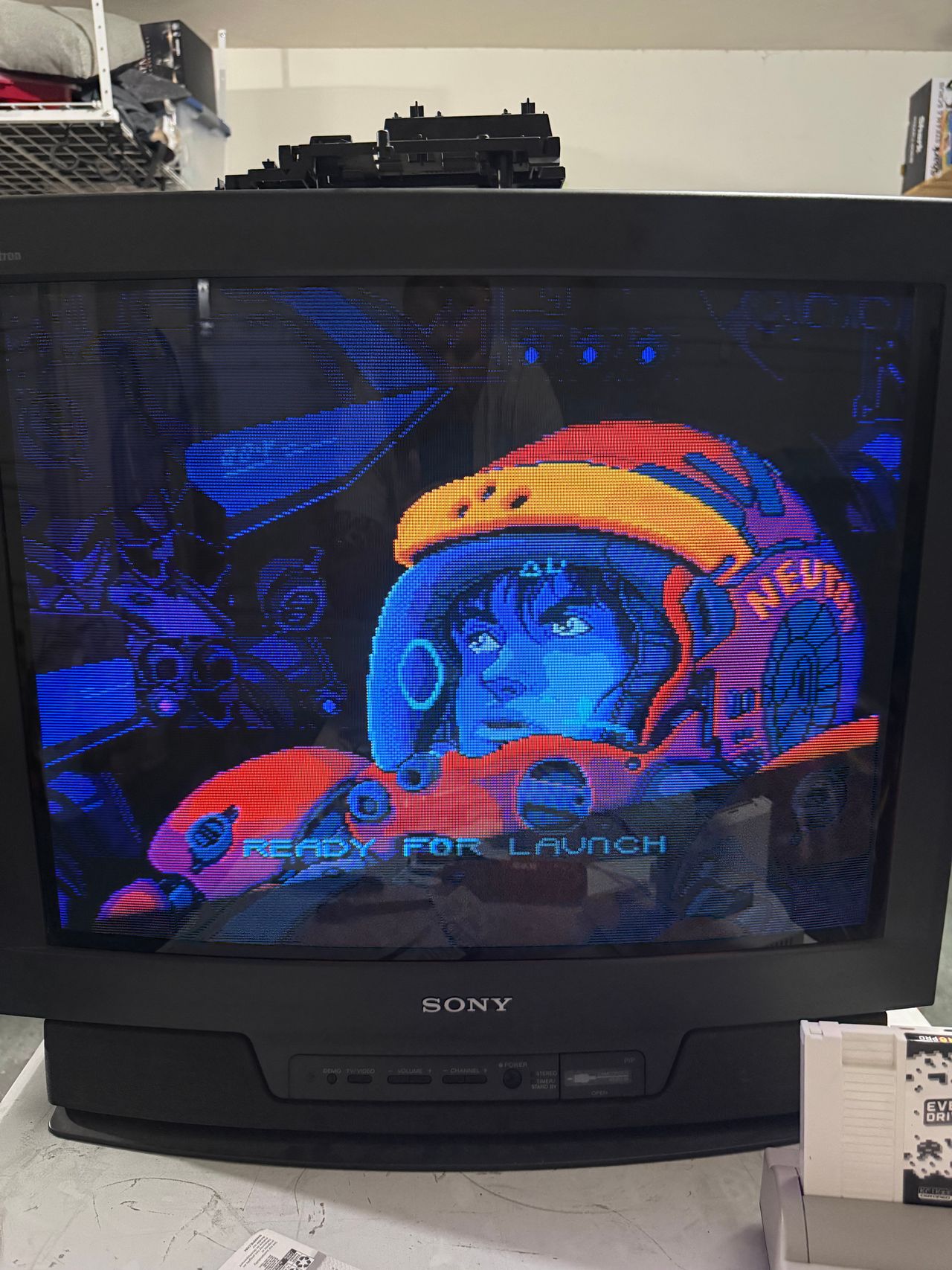
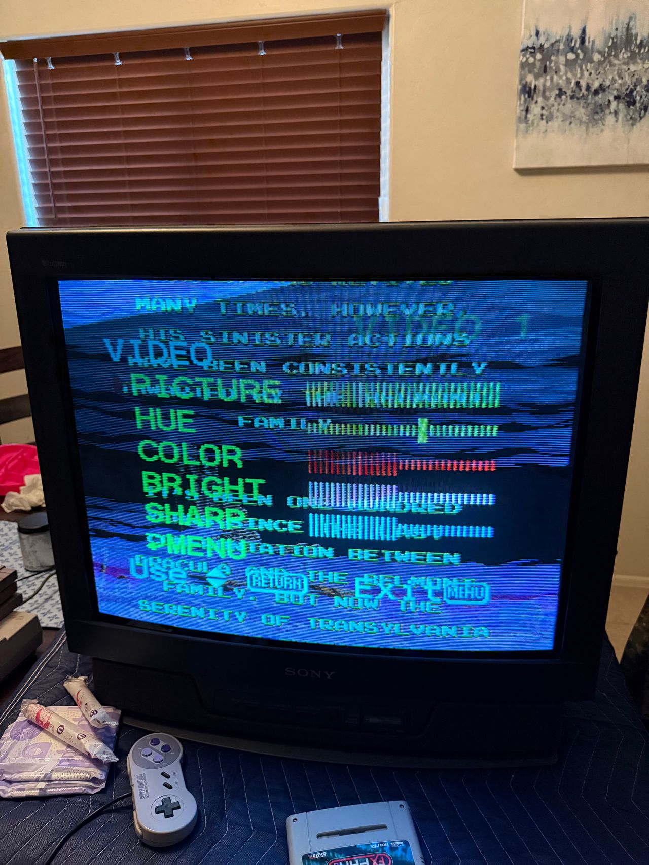
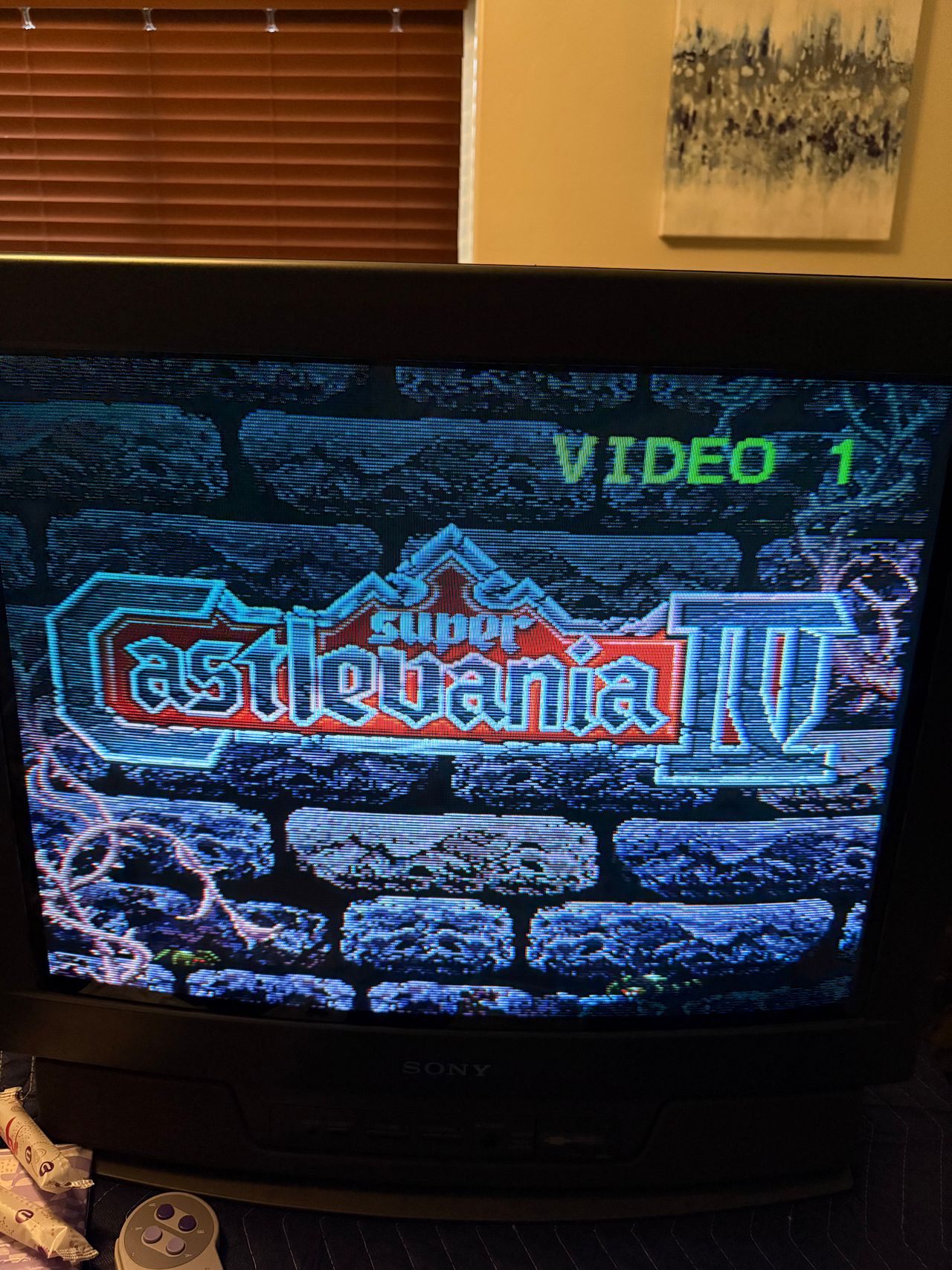
Mod Photos
RGB modification showcase of a Sony KV-27TS36 CRT.
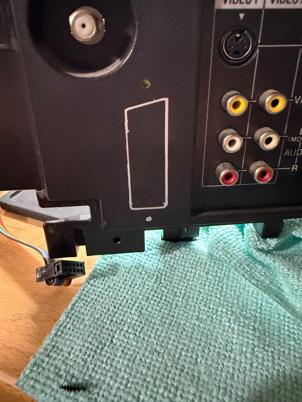
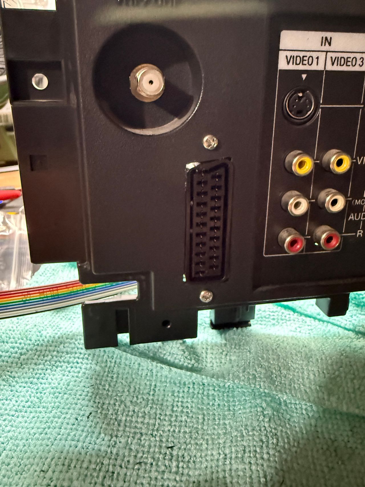
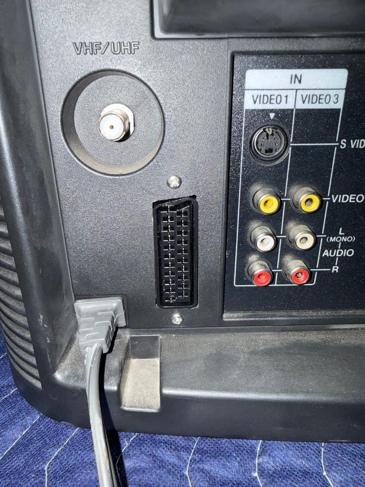
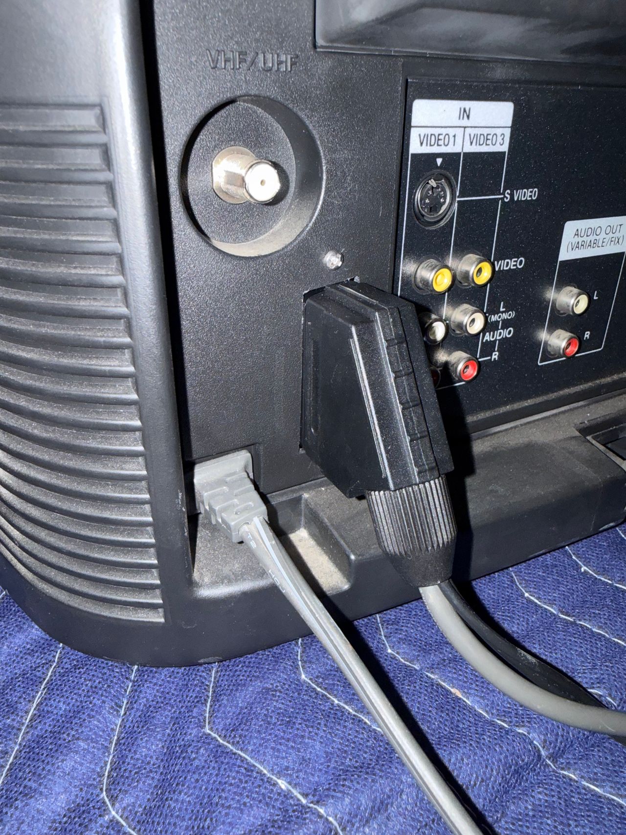
Reference Photos