Sony (BA-5D) KV-36FS100
Sony (BA-5D) KV-36FS100 CRT RGB mod
This tutorial covers the RGB mod for Sony KV-36FS100.
View full CRT details and more mod examples →
Contributors
Thank you to everyone who contributed to this guide:
- Eli Krause — contributor, CRT specs from CRT Database.
- Devon Sanchez — contributor, RGB mod pictures
CRT safety
Caution
You can die doing this! So read carefully! CRT TV is not a toy. Do not open a CRT TV. If you don't have any prior knowledge about handling high voltage devices, this guide is not for you. CRT TV contains high enough voltage (20,000+ V) and current to be deadly, even when it is turned off.
Plan of attack
Manuals and Datasheets
- Sony KV-36FS100 Service Manual — Available for Pro Users only. See CRT details for access.
- Sony KV-36FS100 Service Manual — Available for Pro Users only. See CRT details for access.
Specs
- Year: 2002
- Format: NTSC
- Chassis: BA-5D
- Tube: Sony FD Trinitron A90LPW80X
- Jungle Chip: Sony CXA2154/5AS
- OSD Chip: Mitsubishi M306V5ME-109SP
- Screen Size: 36"
- Inputs: Composite, S-Video, RF, Component YPbPr
Schematics
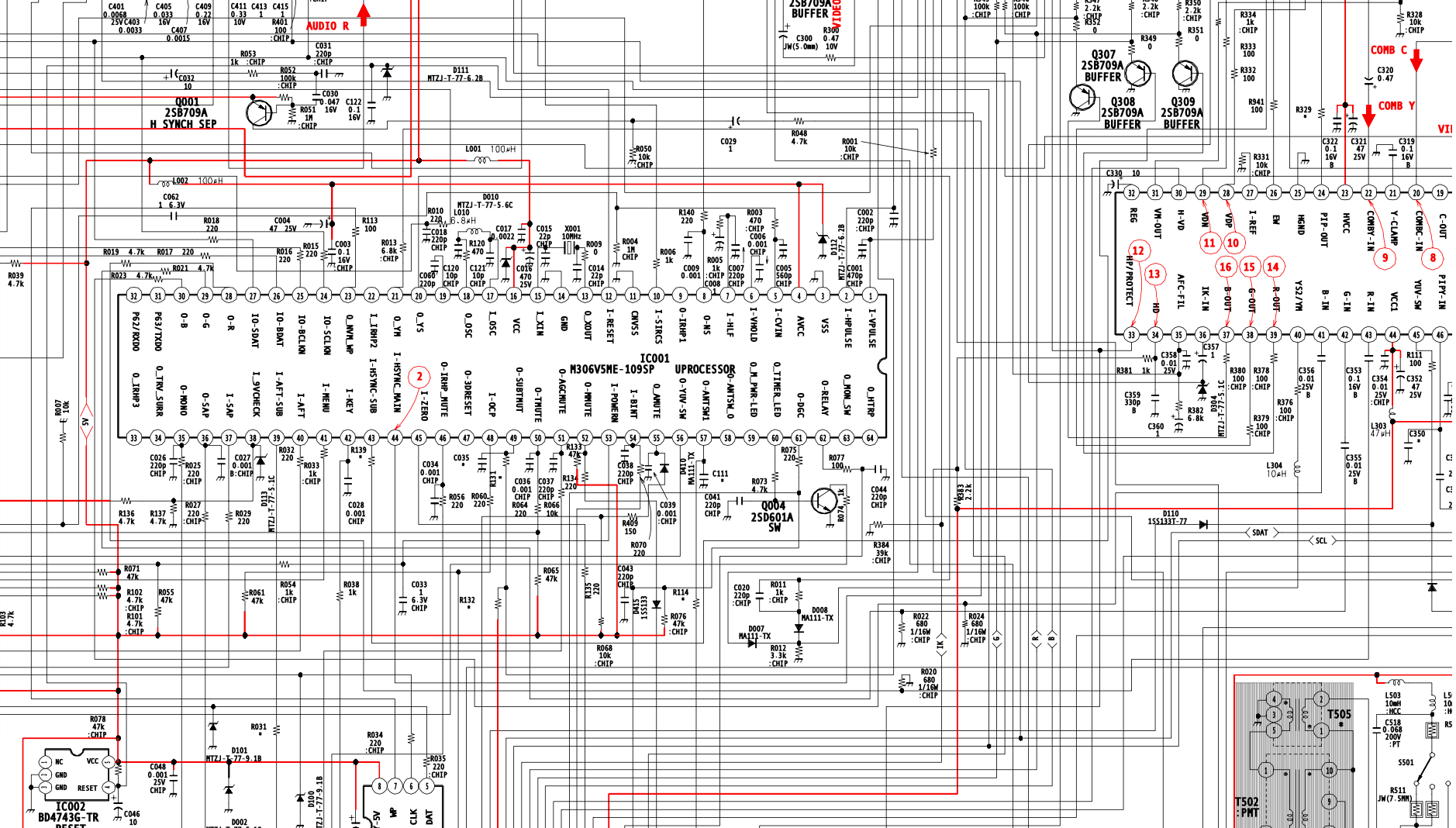
RGB mux diagram
Prepare the mux diagram. If you are building your own circuit, this diagram should help.
Performing the mod
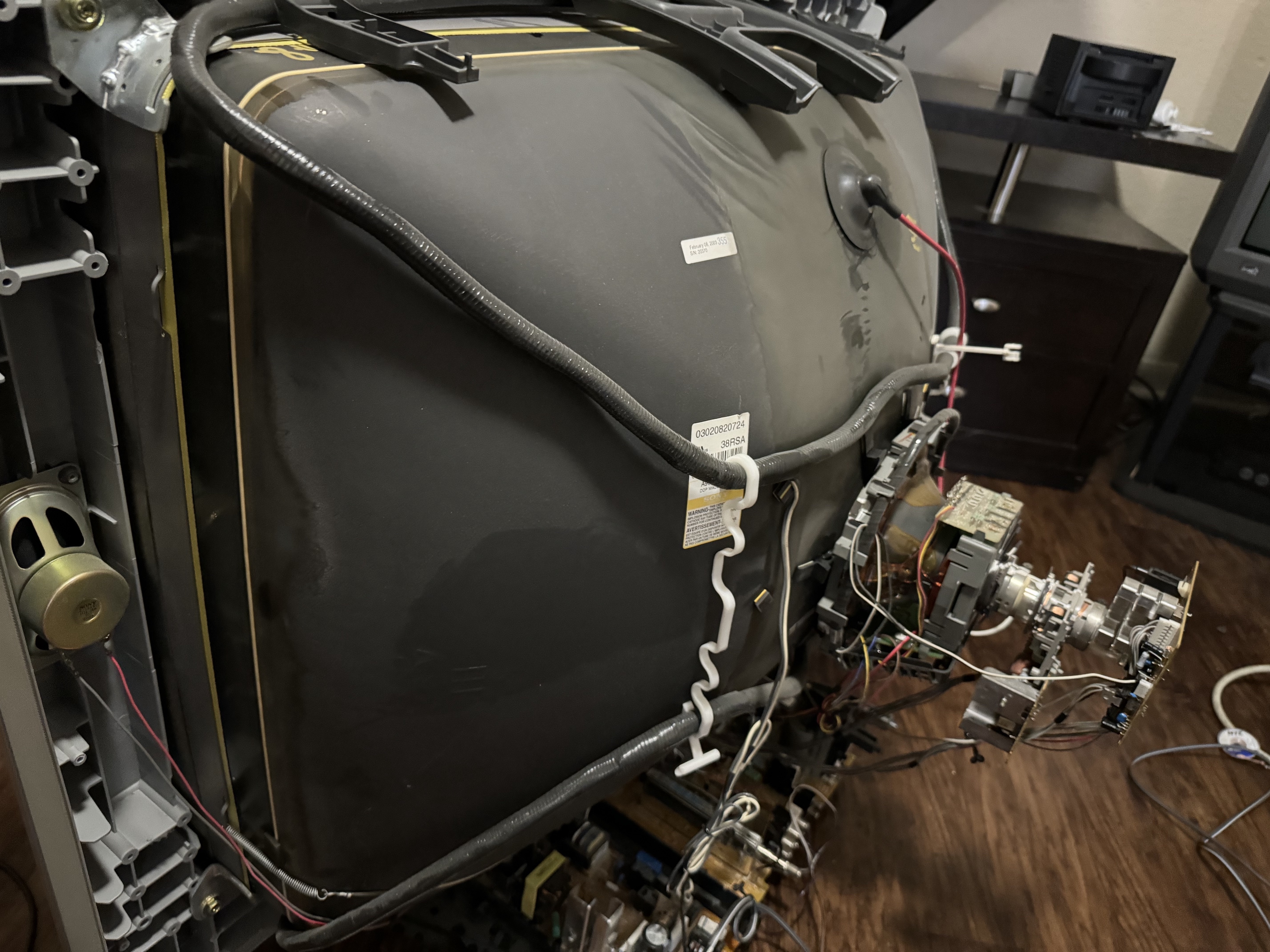
Now that you roughly know what needs to be done, prepare for the mod. Place the board on a comfortable place. Make sure you are not putting pressure on the flyback or other components. There are few wires that needs to be disconnected.
- Degauss wire
- Power wire
- Ground wire attached to the neck board
- Yoke deflection coil wire
- Anode wire (this is the one with the rubber cap)
- Left and right audio wires
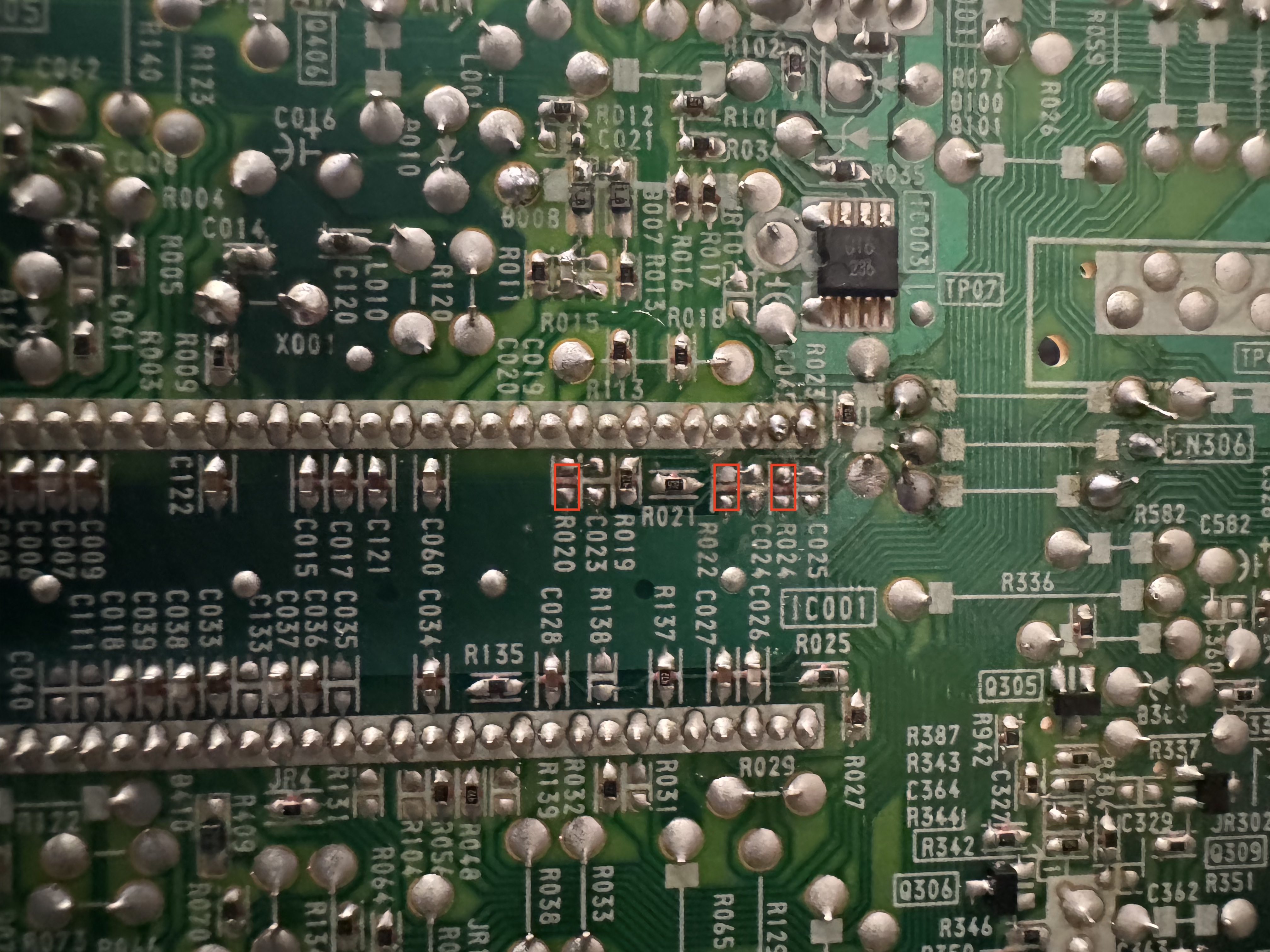
STEP 1: Remove the following components
- R020
- R022
- R024
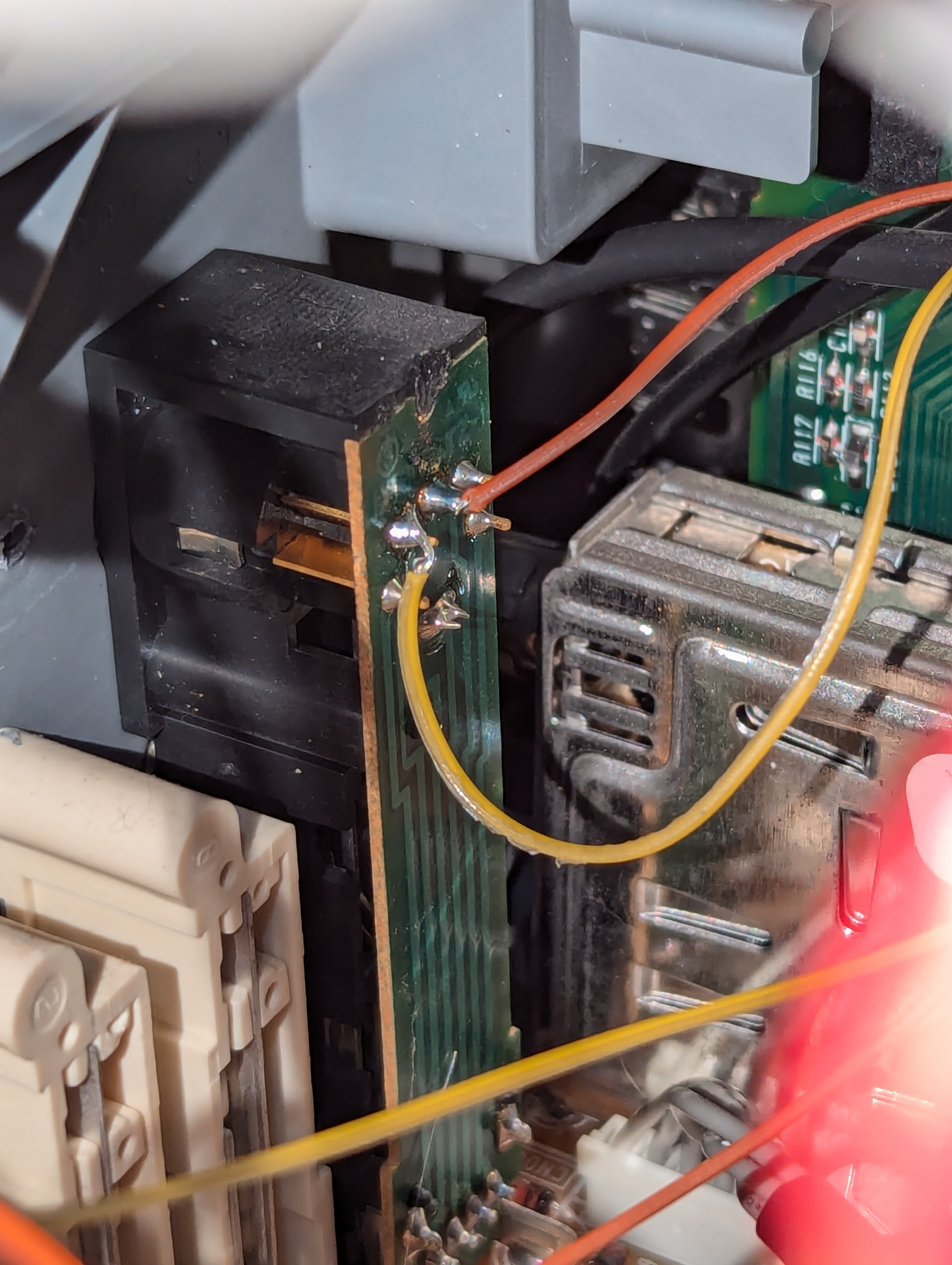
STEP 2: Connect RGB
Replace jumpers JW42 (green), JW43 (blue), JW44 (red) with diodes.
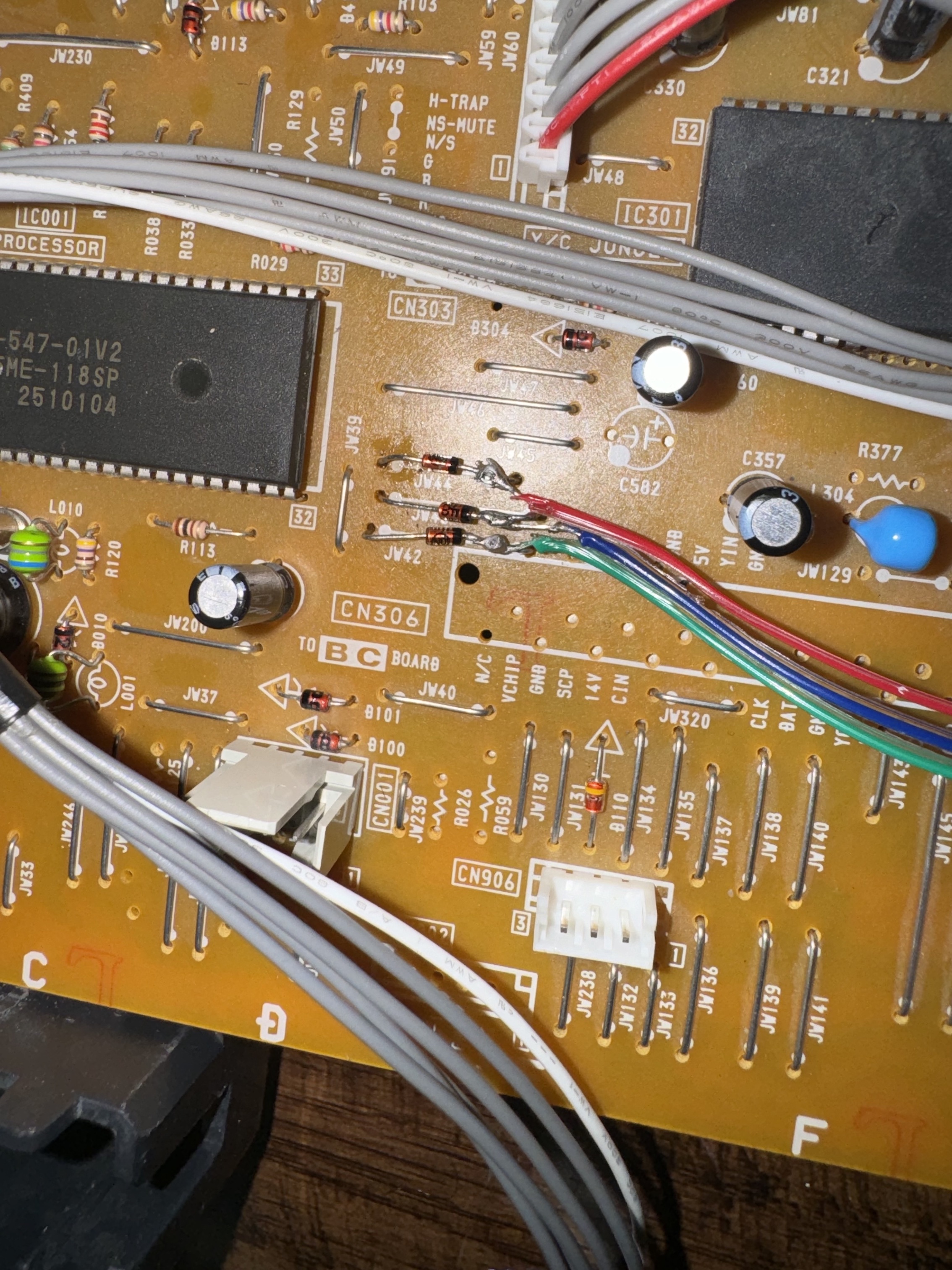
STEP 3: Connect Blanking
3V is the caluclated voltage for blanking. We can calculate 1.2kΩ resistance needed on the RGB mux board with a diode to produce the correct blanking voltage.
![]()
Alternate location to connect blanking
![]()
STEP 4: Connect Sync
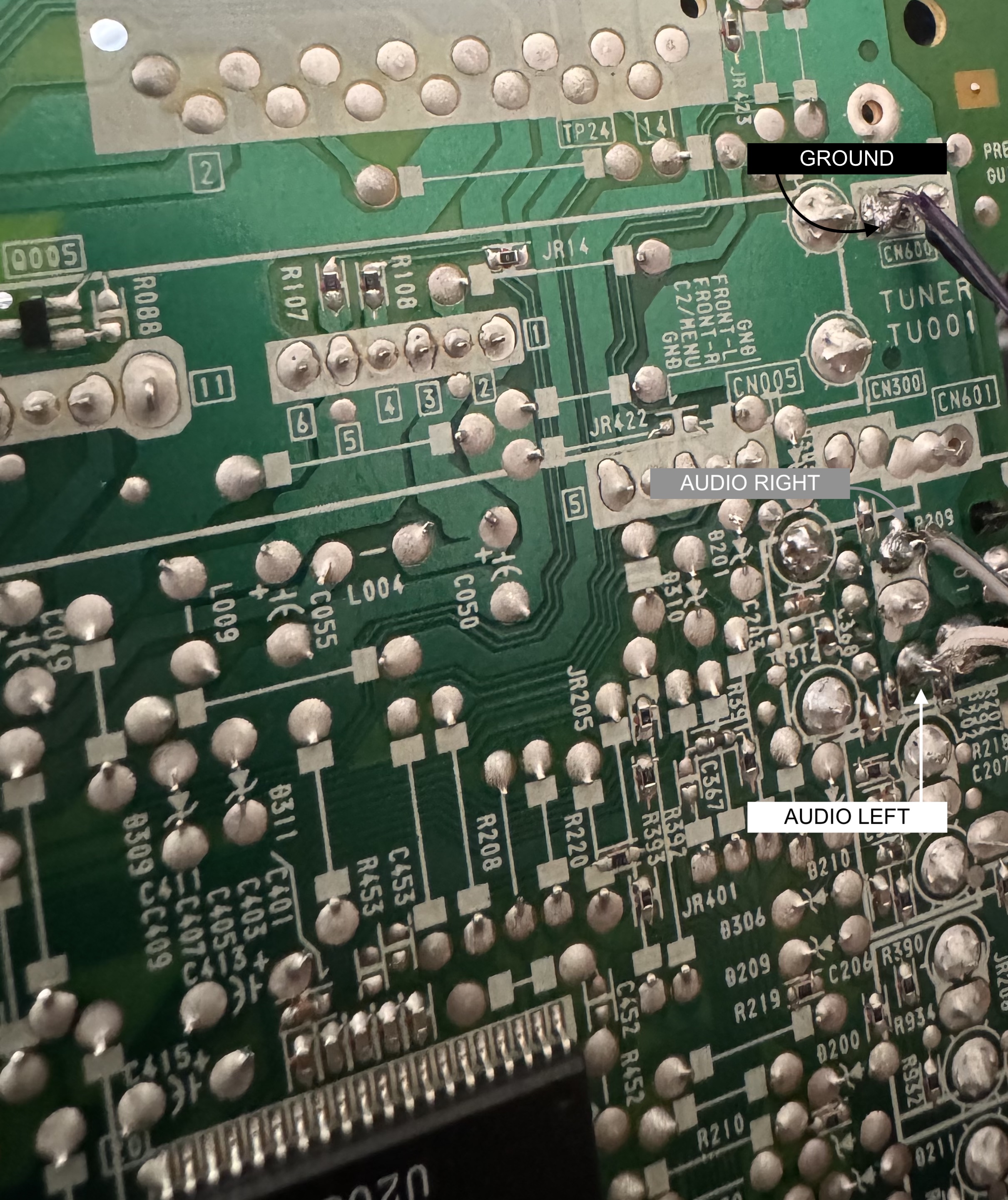
STEP 5: Connect Ground and Audio
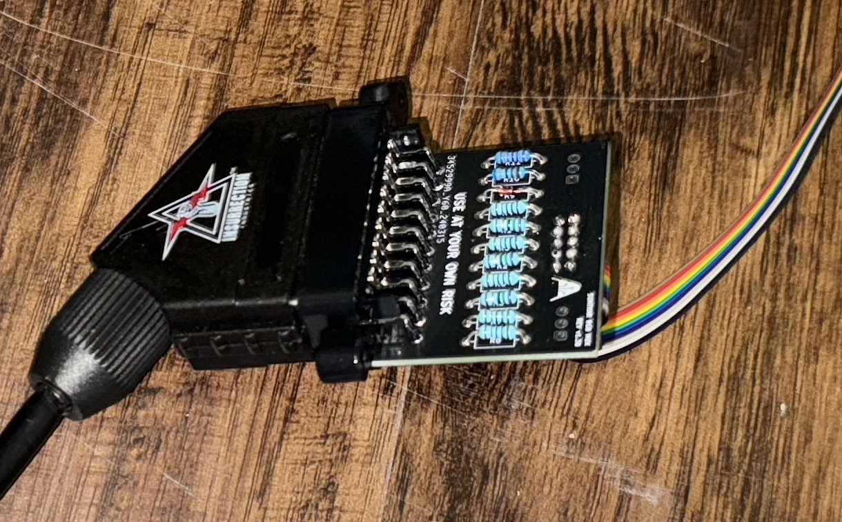
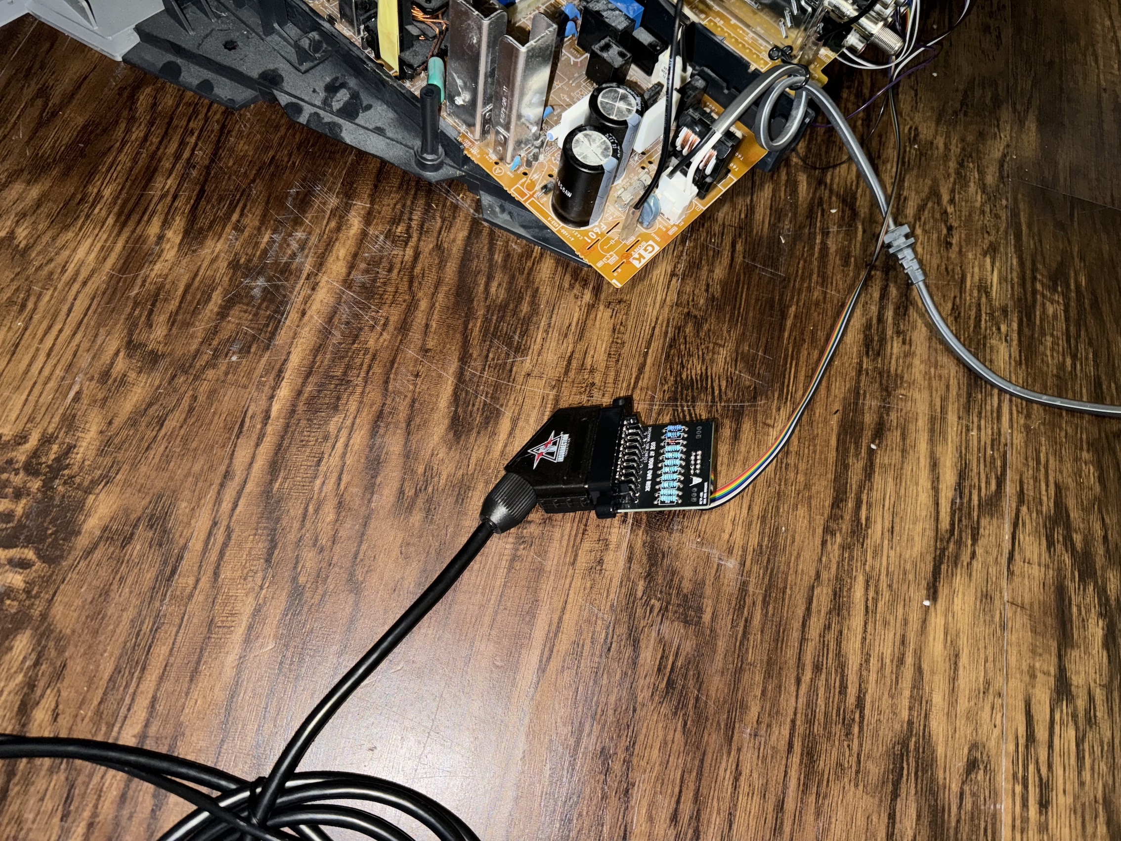
STEP 6: Build your mux board
This mod uses the RGB mux board. This is optional, but will make your mod easier and stable. You can also create the circuit presented in the schematics above without the board. Please also checkout the mux calculator to play with your own values.
| On Sony CRT Chassis | KV-36FS100 |
|---|---|
| CRT RGB inline resistor | 4.7kΩ |
| CRT RGB ground resistors removed | 680Ω |
| 0.1μF caps replaced | No |
| Add diodes on chassis RGB lines? | Yes |
| Add blanking diode on chassis | No |
| RGB mux board | KV-36FS100 |
|---|---|
| Mux board RGB termination (R1, R2, R3) | 75Ω |
| Mux board RGB inline resistors (R4, R5, R6) | 1kΩ |
| Mux board Audio LR (R7, R8) | 1kΩ |
| Mux board blanking diode (R9) | 1N4148 |
| Mux board blanking ground resistor (R10) | open |
| Mux board blanking resistor (R11) | 1kΩ |
| Mux board transistor base resistor (R12) | 1kΩ |
| Mux board transistor (Q1) | PN2222A |
Compatible mux boards:
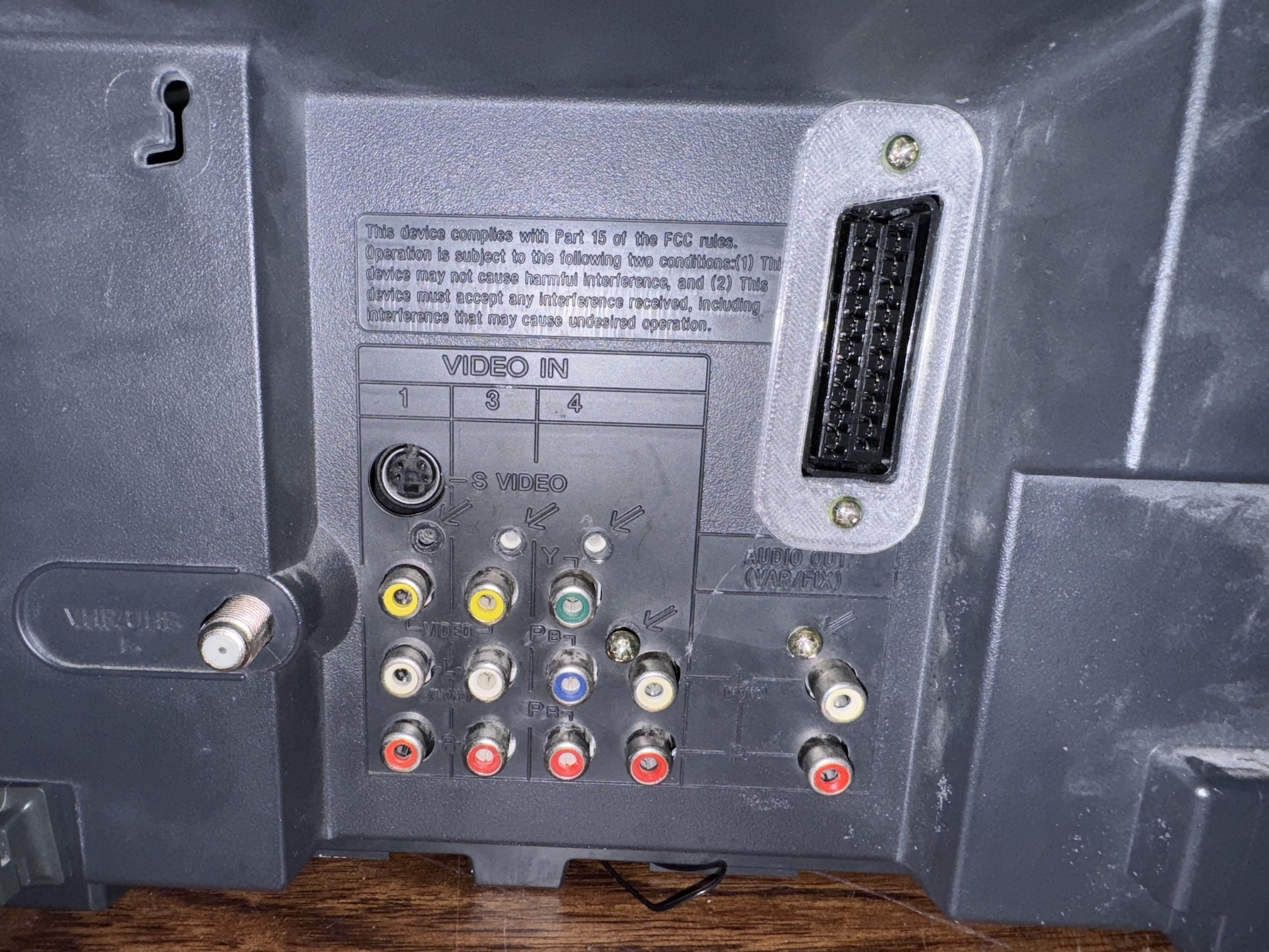
STEP 7: Attach the female SCART connector to TV
Creating a SCART cutout and mounting it is an art. I have a dedicated section for it. How to create and mount a SCART female plug?
Pictures
Flux issue (pictures shared by Cristian Mendez KV-27FV300)
KV-27FV300 is pretty much the same as KV-36FS100 expect for an inclusion of a BC board and a subwoofer.
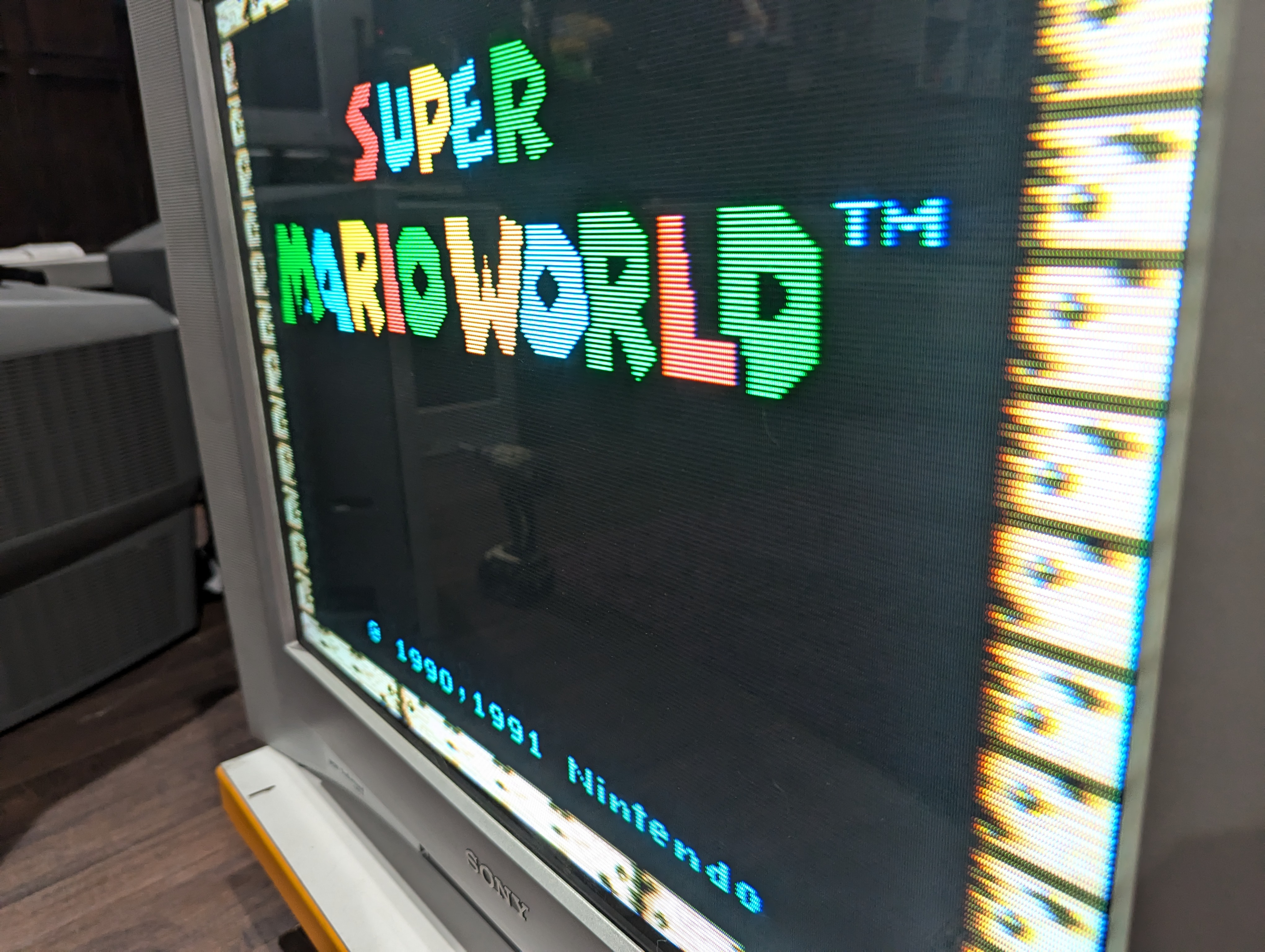
Below image shows flux all over the IDC pins. 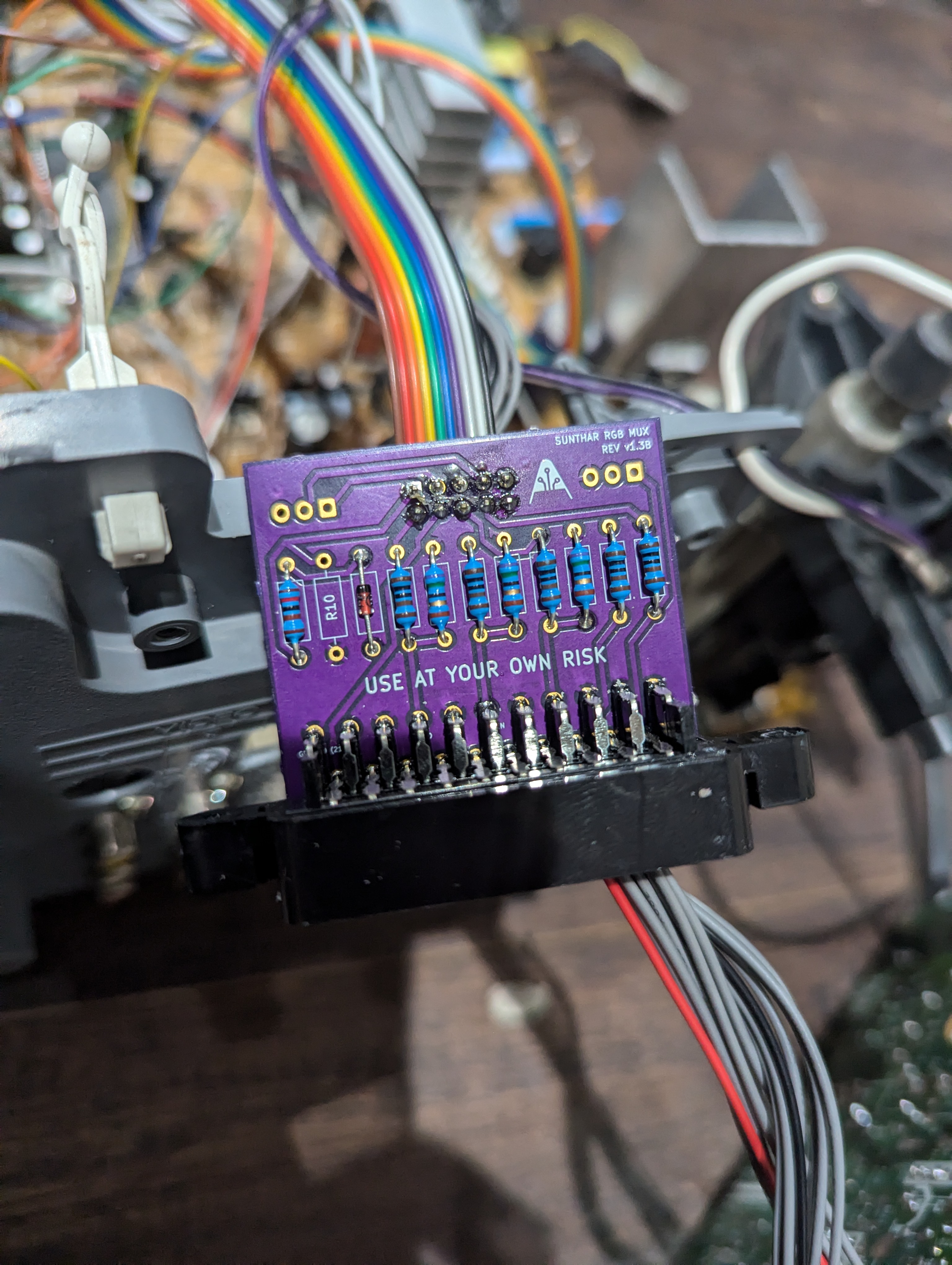
When there is flux present, such as when resistors are removed on the main chassis or when soldering components on the mux board, it can cause a small amount of current to leak, leading to various kinds of interference. Below picture shows the white bar seen on the right side and the noise noticed.
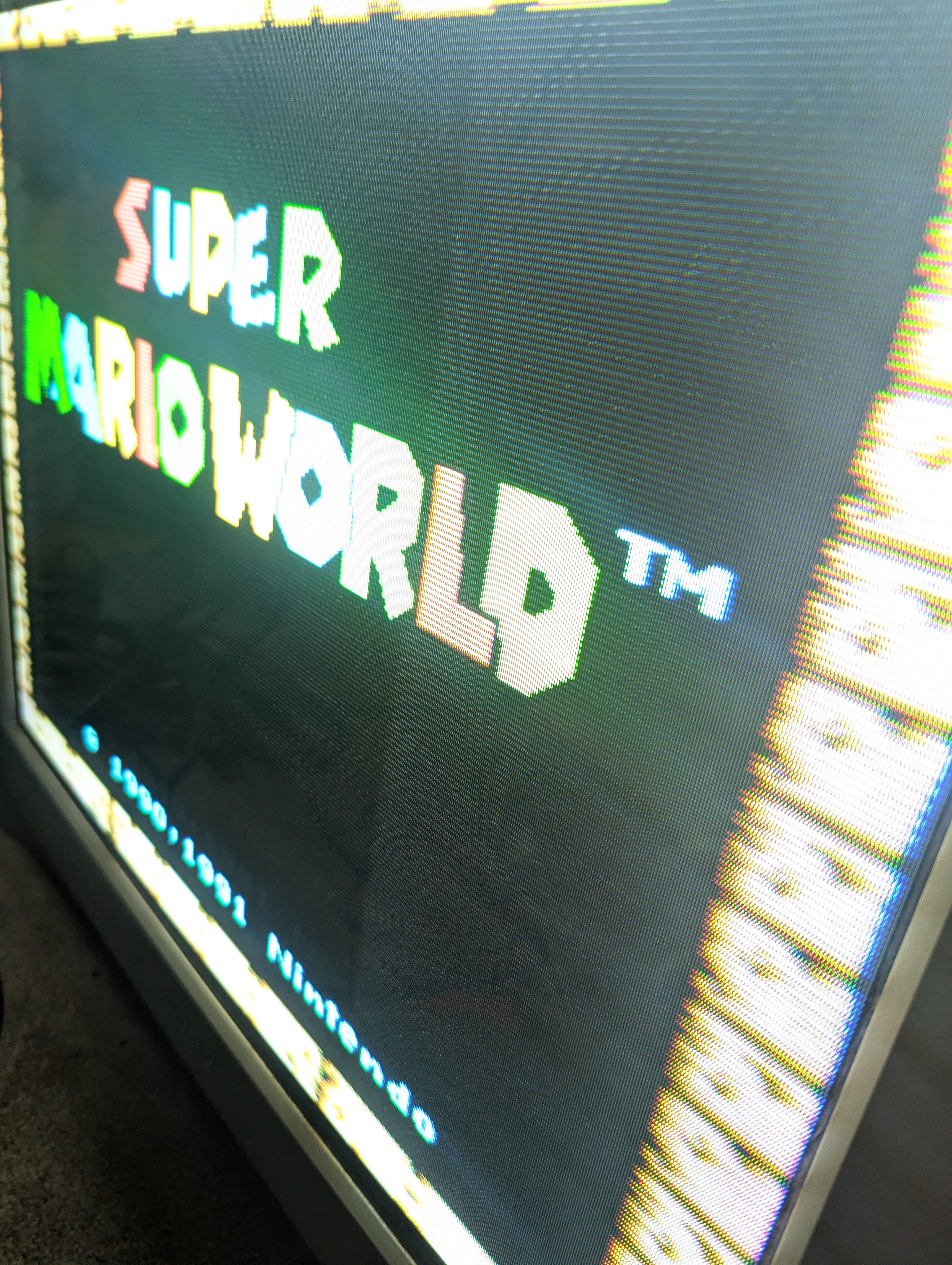
After cleaning the flux and ensuring the ribbon cable is crimped properly, you can see the image is much cleaner and free of noise.
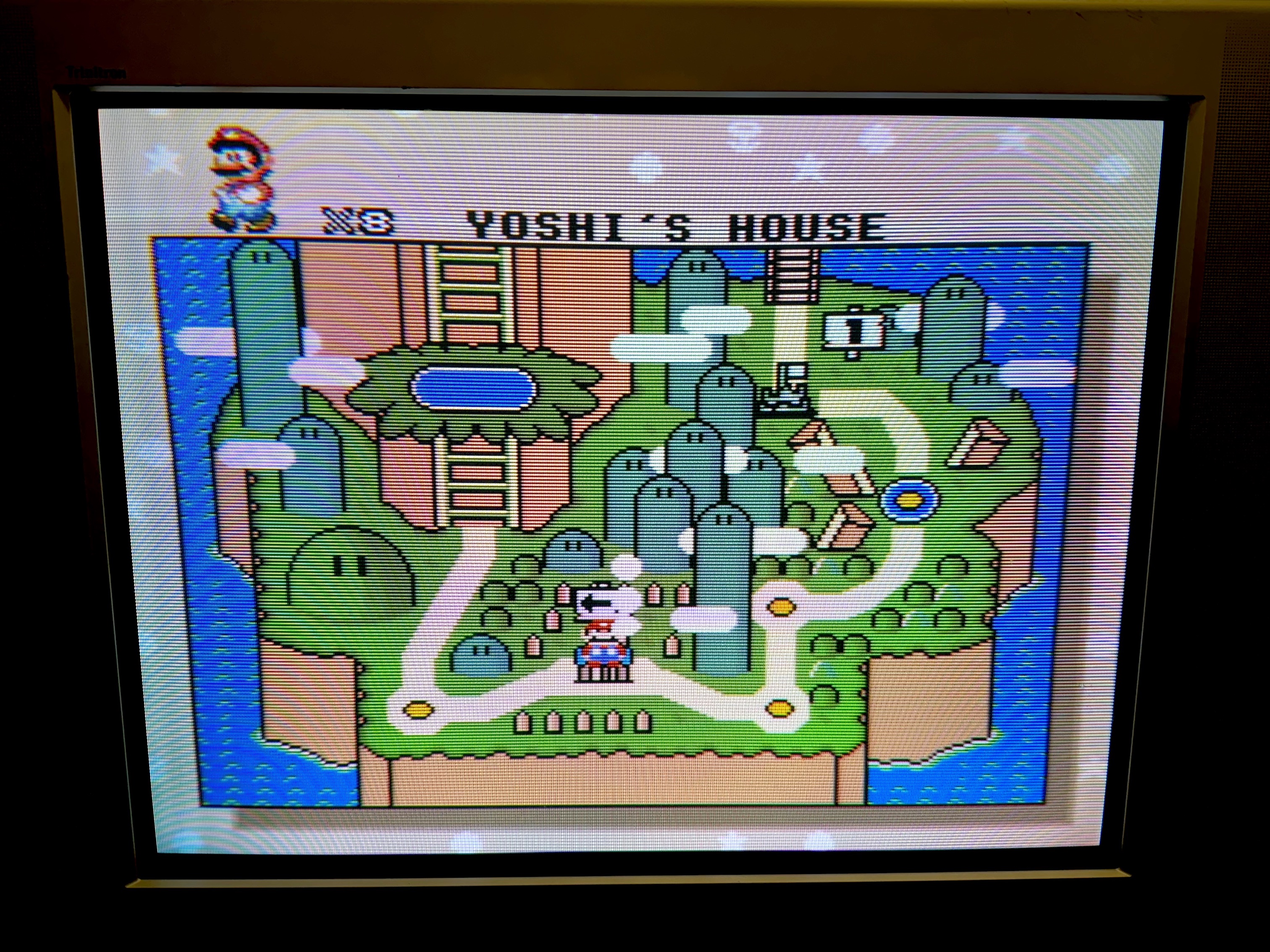
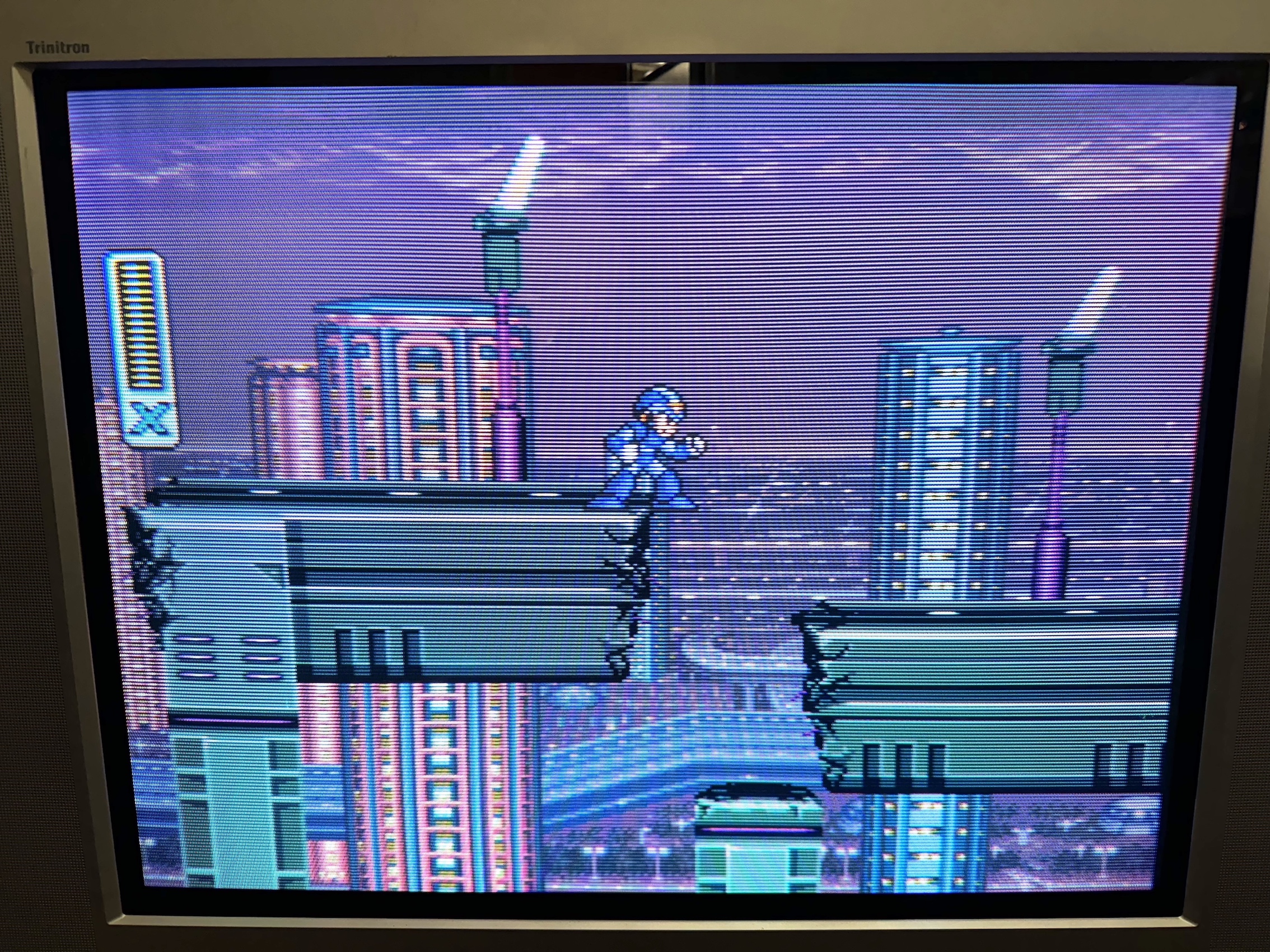
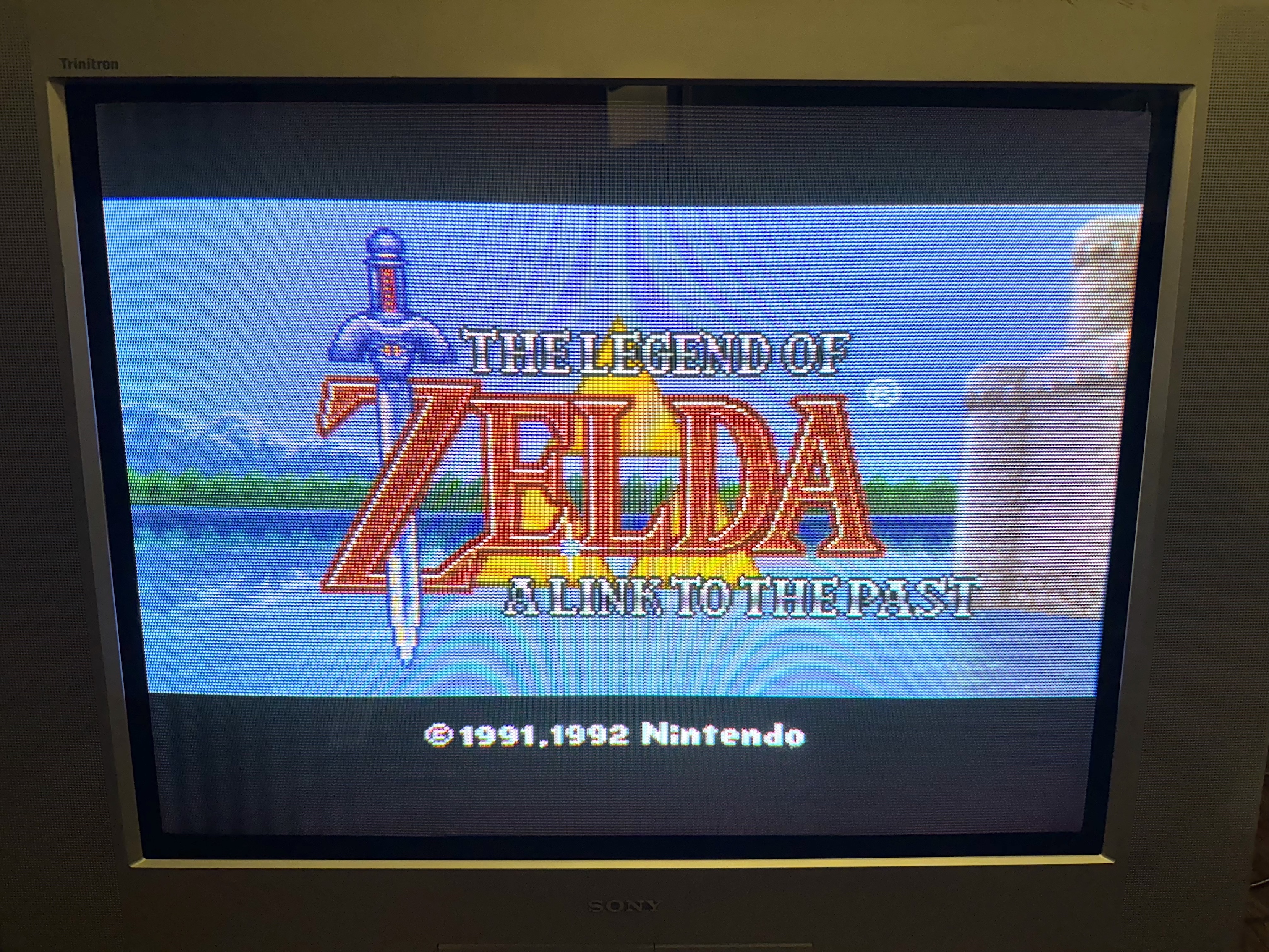
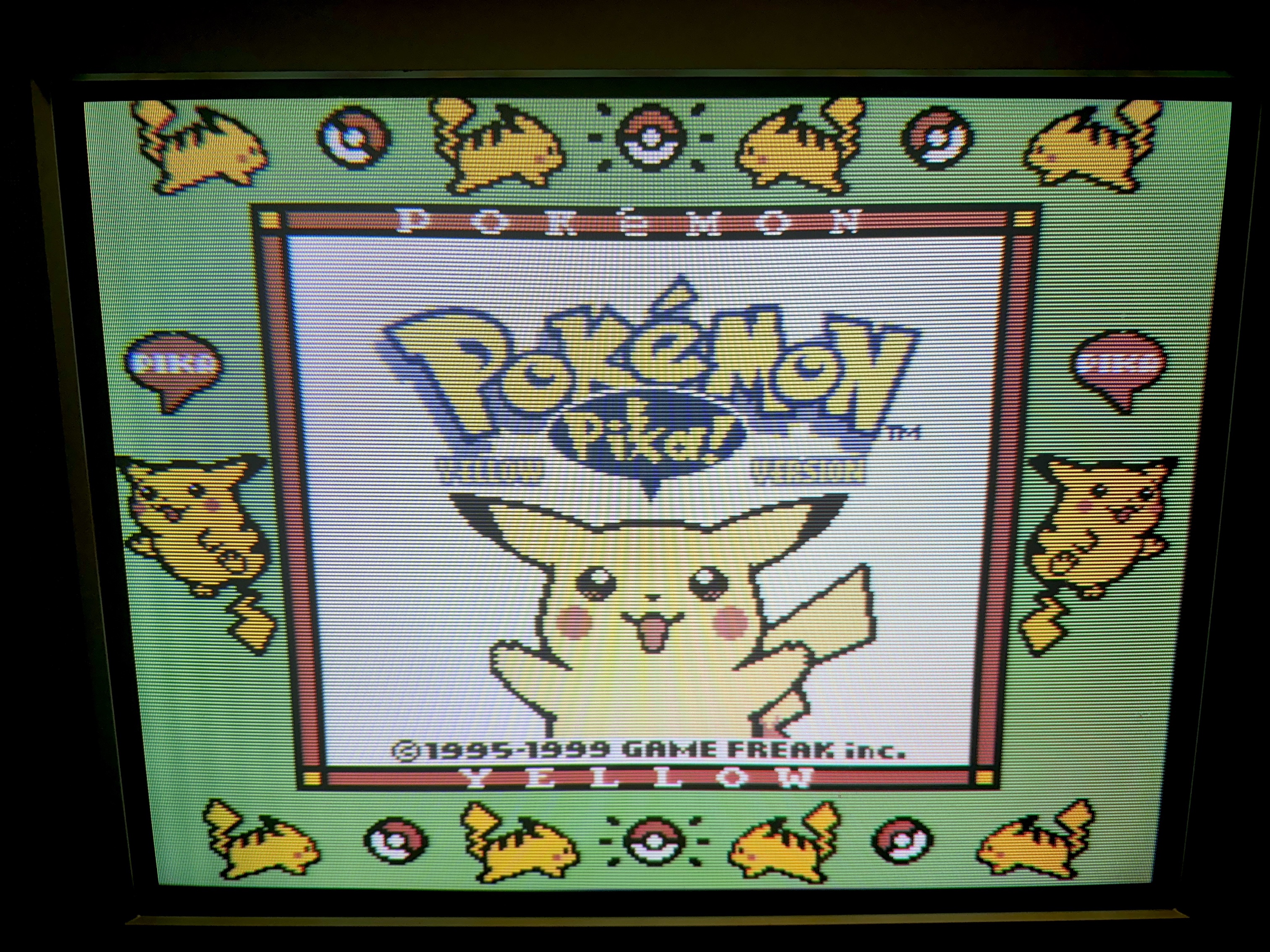
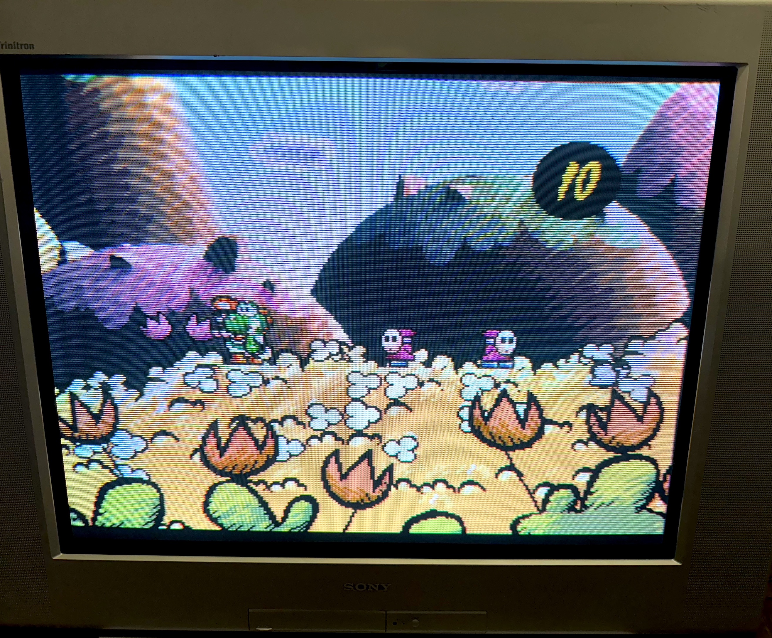
Games
TV