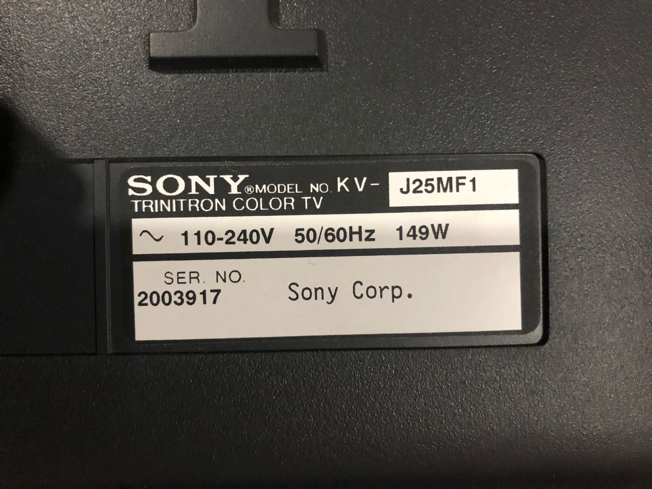
Sony (BG-1L) KV-J25MF8J
Sony (BG-1L) KV-J25MF8J CRT RGB mod
The Sony KV-J25MF8J is a 25" curved CRT television built around the highly versatile BG-1L chassis. It is a prized multi-format international model capable of handling worldwide video signals (PAL, NTSC, SECAM) and operating on universally adaptable voltages.
View full CRT details and more mod examples →
I changed few capacitors to aluminum ploymer or ceramic. Several caps were also changed near the deflection circuits. It was noticed the traces were fairly fragile on Board A. Please keep this in mind, this set largely did not need any new capacitors.
Contributors
Thank you to everyone who contributed to this guide:
- Sunthar — contributor, CRT specs and RGB mod
CRT safety
Caution
You can die doing this! So read carefully! CRT TV is not a toy. Do not open a CRT TV. If you don't have any prior knowledge about handling high voltage devices, this guide is not for you. CRT TV contains high enough voltage (20,000+ V) and current to be deadly, even when it is turned off.
Plan of attack
Manuals and Datasheets
Specs
- Format: PAL, PAL60, SECAM, NTSC4.43, NTSC3.58
- Chassis: BG-1L
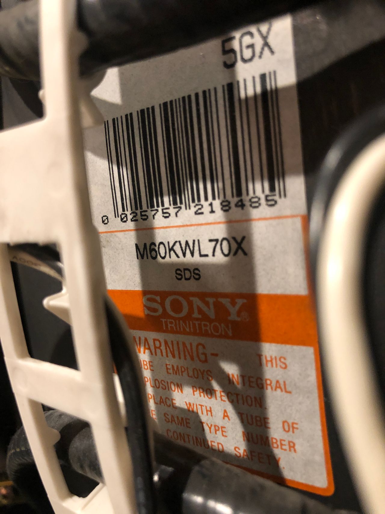
- Tube: Super Trinitron Tube M60KWL70X
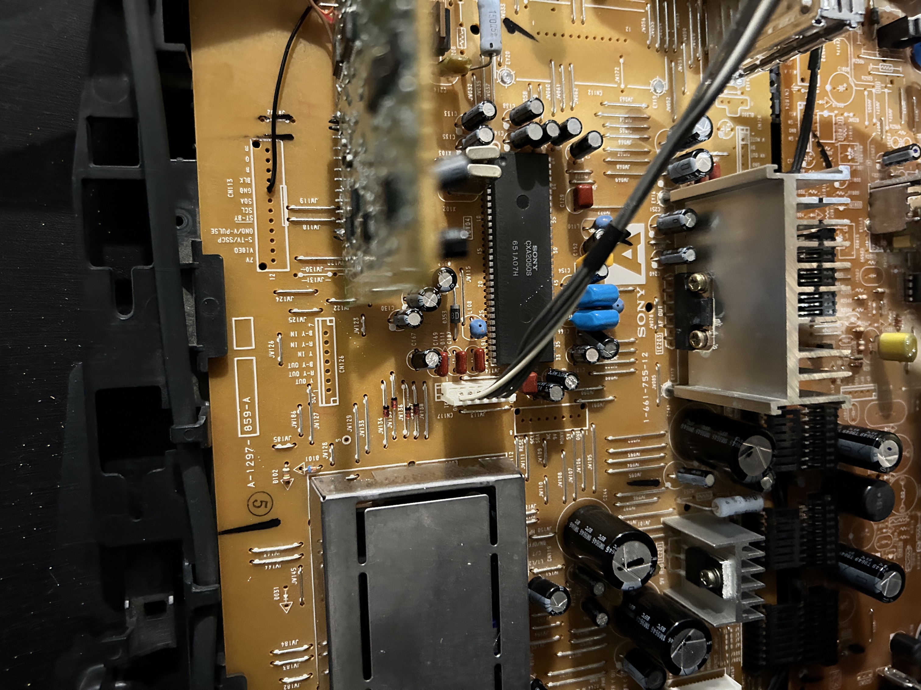
- Jungle Chip: Sony CXA2050S
- OSD Chip: Sony CXP85332A-238S
- Screen Size: 25"
Schematics
Calculated 910Ω for 0.7Vp-p. With diode inline for RGB, you have to use 1kΩ.
Adding S-Video at the back
This is as simple as adding the missing components. Follow the diagram below to see how to populate for S-Video. Adding S-Video is optional.
I was able to source the S-Video connector from a broken Toshiba 27AF44 chassis. Rest of the parts were all sourced from mouser. End result was satisfying and S-Video input 1 worked flawlessly. Later, I used the luma to feed in the sync.
RGB mux diagram
Prepare the mux diagram. If you are building your own circuit, this diagram should help.
Performing the mod
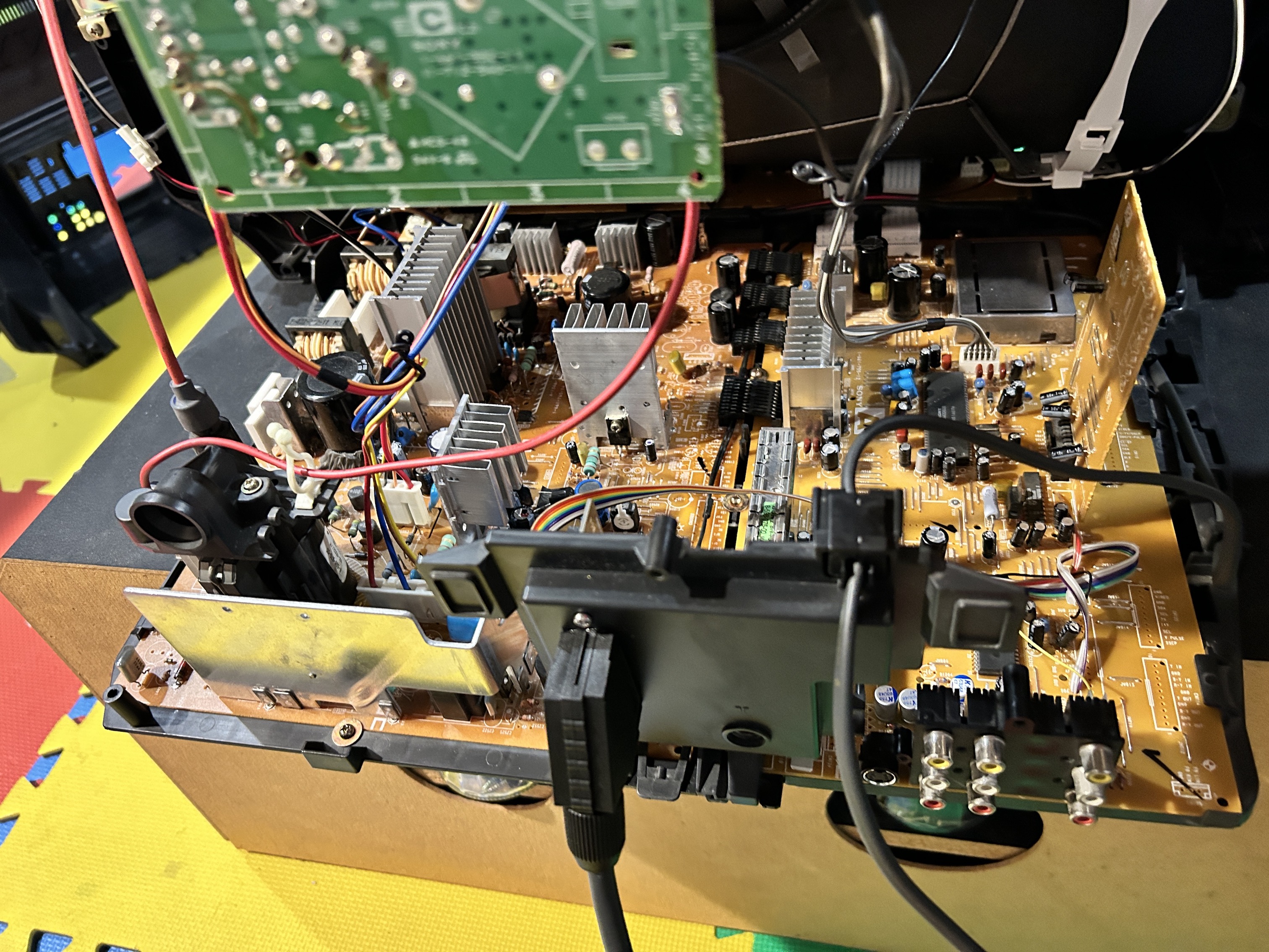
Now that you roughly know what needs to be done, prepare for the mod. Place the board on a comfortable place. Make sure you are not putting pressure on the flyback or other components. Taking out the chassis is fairly straight forward on this CRT. There are few wires that needs to be disconnected.
- Degauss wire
- Power wire
- Ground wire attached to the neck board
- Yoke deflection coil wire
- Anode wire (this is the one with the rubber cap)
- Left and right audio wires
Please remember that wires 1-5 are critical for the CRT to function and should not be omitted. Having any of these wires disconnected while powering up can damage the board and can have adverse effects.
It should also be noted, on this CRT, you can do the RGB mod by just taking out the A board. This means you don't even need to remove the anode wire.
Mux diagram
If you are building your own circuit, this diagram should help
While a second set of RGB input is available on CXA2050S, unfortunately on the BG-1L chassis it is disabled in software. There are I2C hacks that can potentially enable this input. However, we don't need to take this harder path. We can simply do a mux mod, which gives a stunning RGB picture.
STEP 1: Remove the following components
Remove the three (1.8 kΩ) ground resistors. These are marked as Cxxx for whatever reason instead of Rxxx.
- C325 (1.8 kΩ)
- C326 (1.8 kΩ)
- C327 (1.8 kΩ)
STEP 2: Connect RGB, Blanking and Ground
Replaced jumpers JW134, JW135, JW136, JW137 with diodes. Diode stripes should be pointing towards the chroma chip. The idea here is to make sure the external RGB input currents don't go towards the OSD chip. Instead these diodes make sure the current is directed towards the chroma IC (CXA2050S).
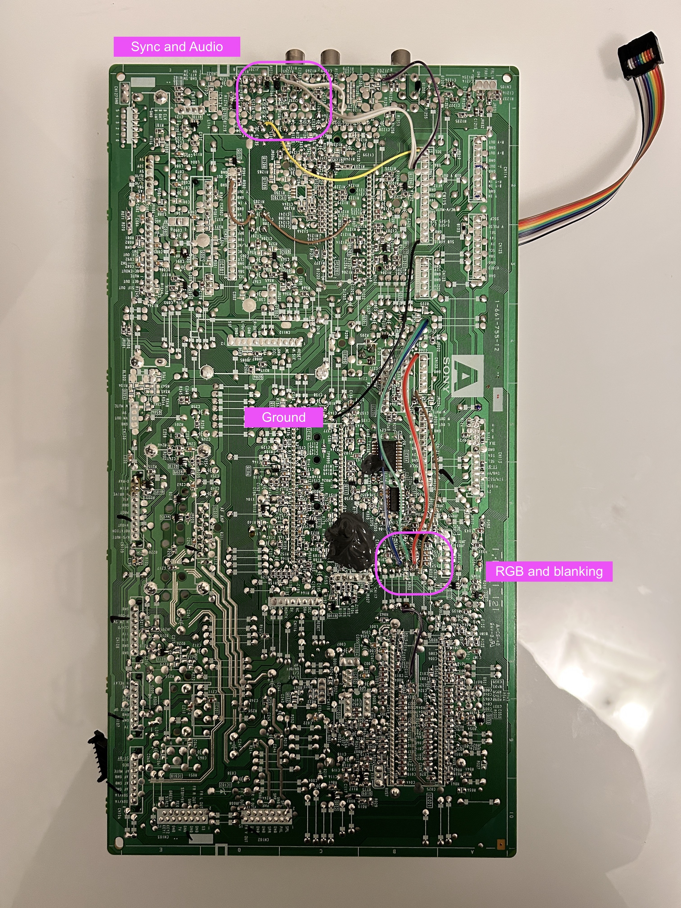
Red, Green, Blue, Blanking ![]()
STEP 3: Connect Audio and Sync
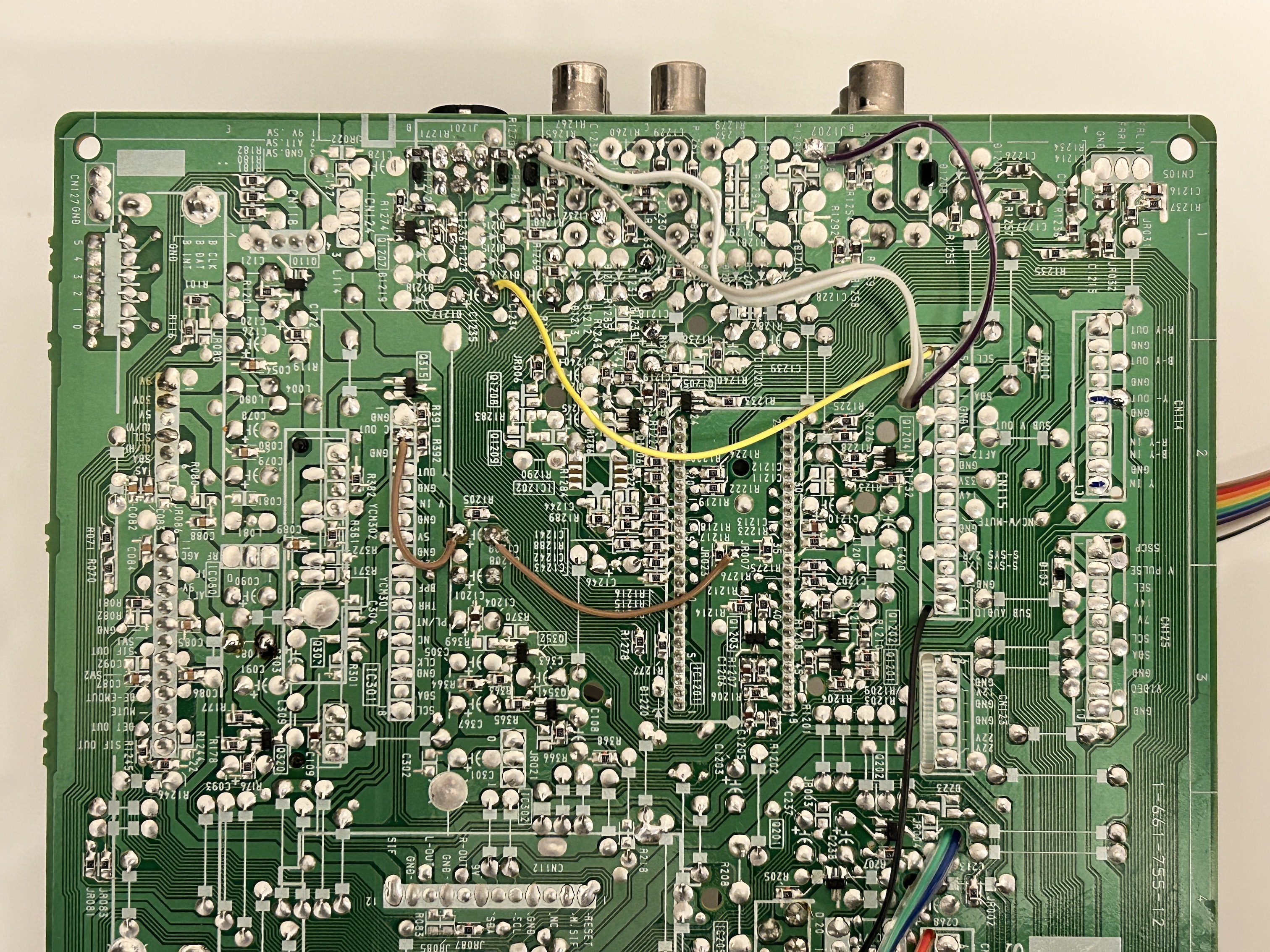
For stereo audio to work, both Video 1 audio left and right inputs should be populated. There is a physical switch inside the red RCA audio port that enables stereo. For sync to work through luma, S-Video port should be populated. When the S-Video port is populated, detect line is grounded signaling the video switch IC to use chroma/luma input instead of the composite video input.
STEP 4: Build your mux board
This mod uses the RGB mux board. This is optional, but will make your mod easier and stable. You can also create the circuit presented in the schematics above without the board. Please also checkout the mux calculator to play with your own values.
| On Sony CRT Chassis | KV-J25MF8J |
|---|---|
| CRT RGB inline resistor | 1.2kΩ |
| 0.1μF caps replaced | No |
| Add diodes on chassis RGB lines? | No |
| Add blanking diode on chassis | No |
| RGB mux board | KV-J25MF8J |
|---|---|
| Mux board RGB termination (R1, R2, R3) | 75Ω |
| Mux board RGB inline resistors (R4, R5, R6) | 180Ω |
| Mux board Audio LR (R7, R8) | 1kΩ |
| Mux board blanking diode (R9) | 1N4148 |
| Mux board blanking ground resistor (R10) | open |
| Mux board blanking resistor (R11) | 2.2kΩ |
| Mux board transistor base resistor (R12) | 1kΩ |
| Mux board transistor (Q1) | PN2222A |
Compatible mux boards:
STEP 5: Attach the female SCART connector to TV
Creating a SCART cutout and mounting it is an art. I have a dedicated section for it. How to create and mount a SCART female plug?
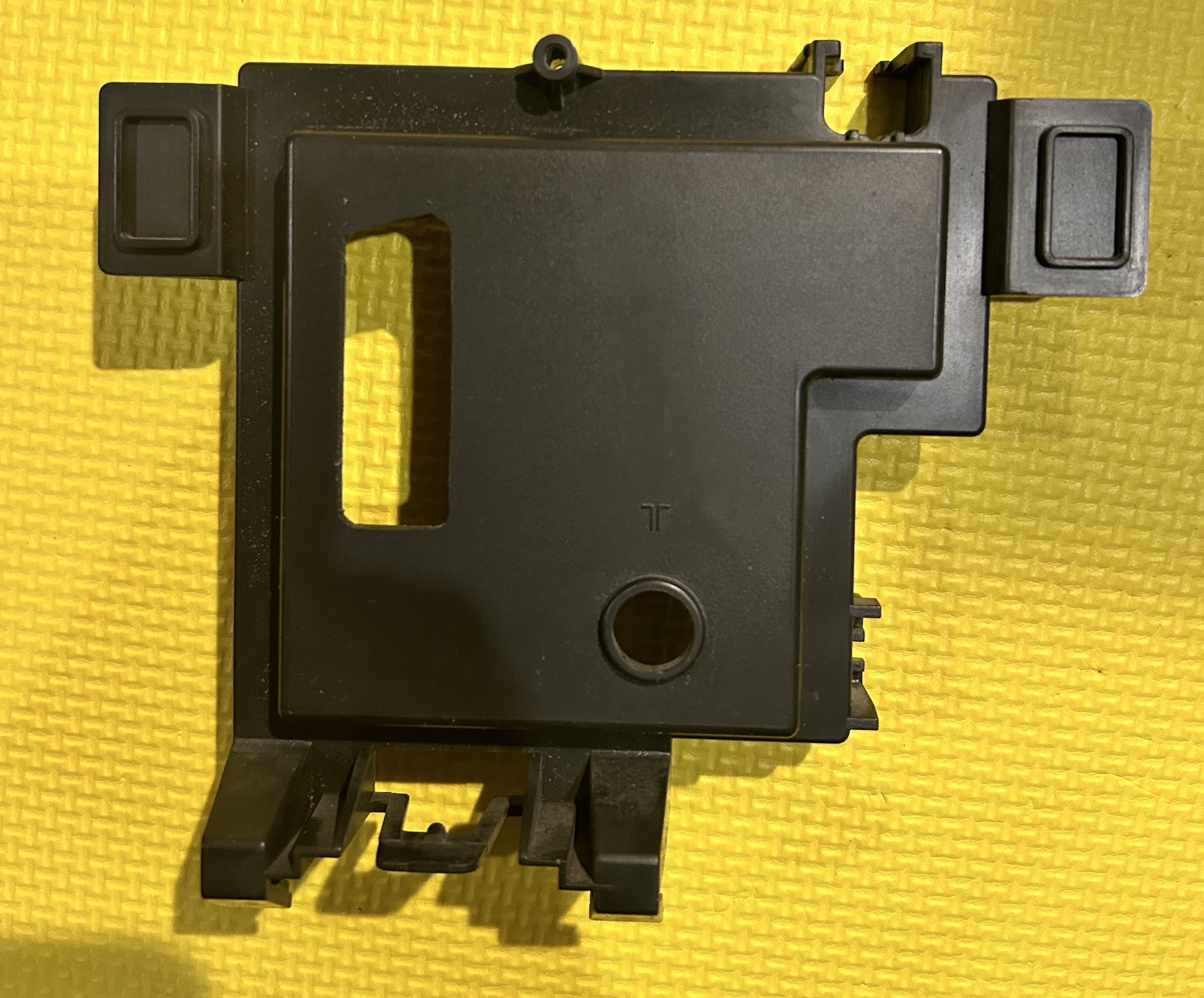
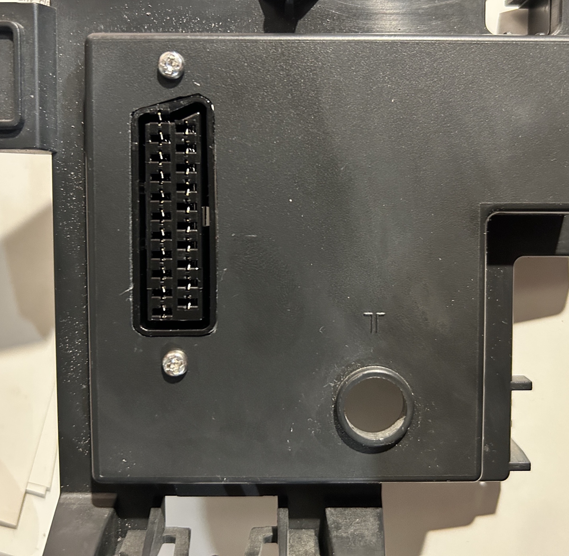
Perfect fit! 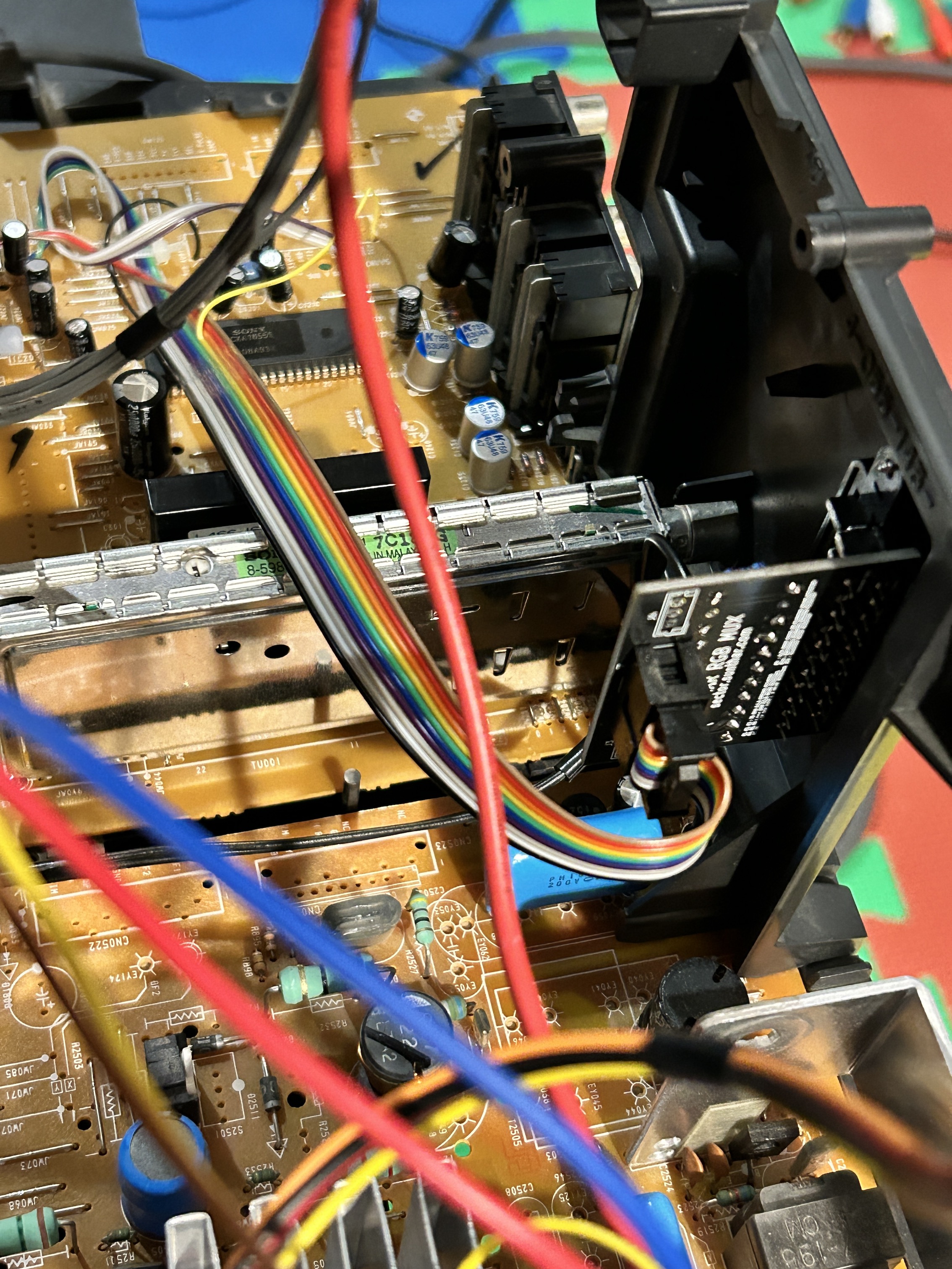
Pictures
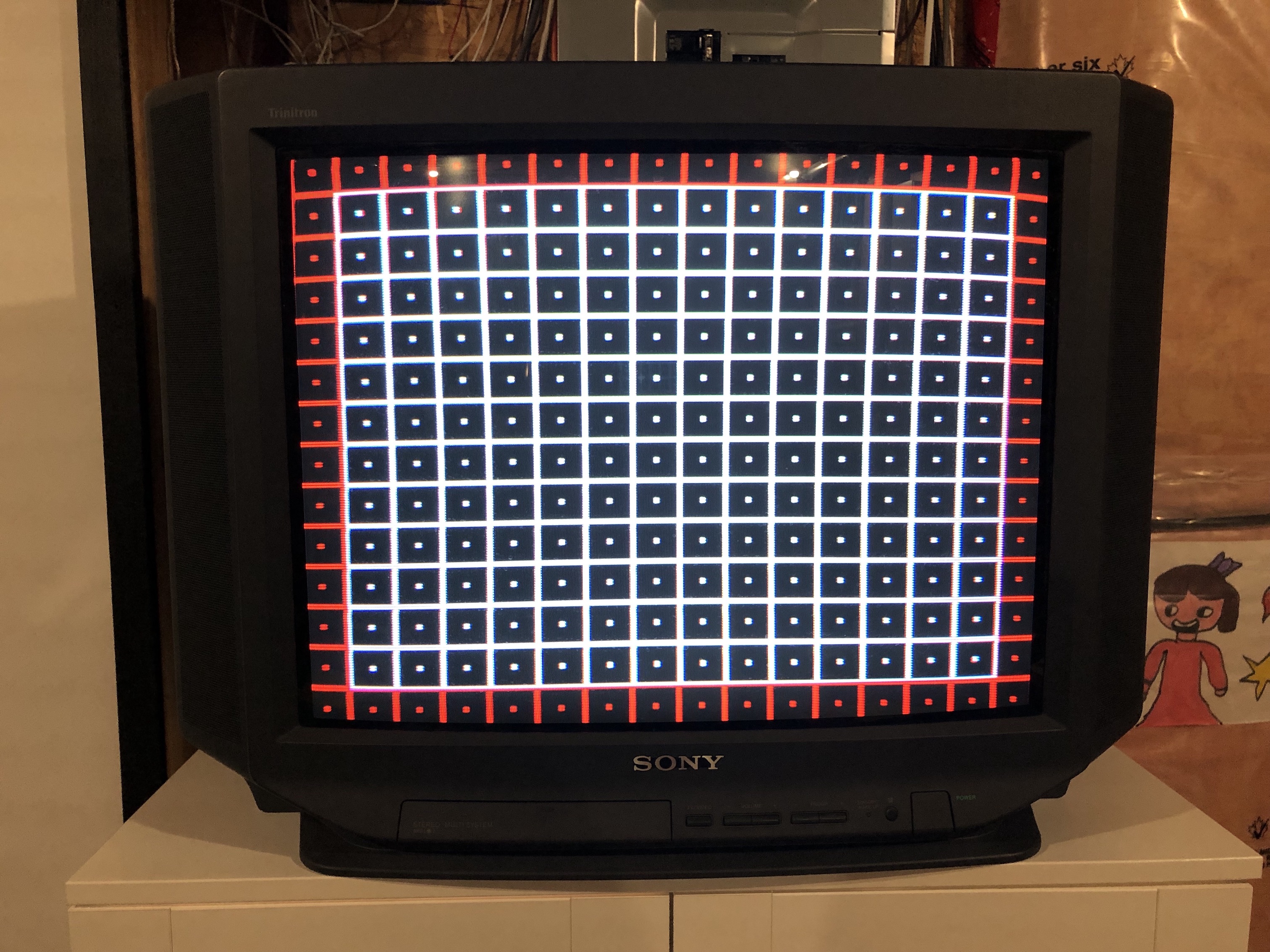
At the time of this writing, yoke of this set was not reseated and convergence was not dialed in. Therefore, you see the bowing on the top.
Mux
OSD on top of RGB 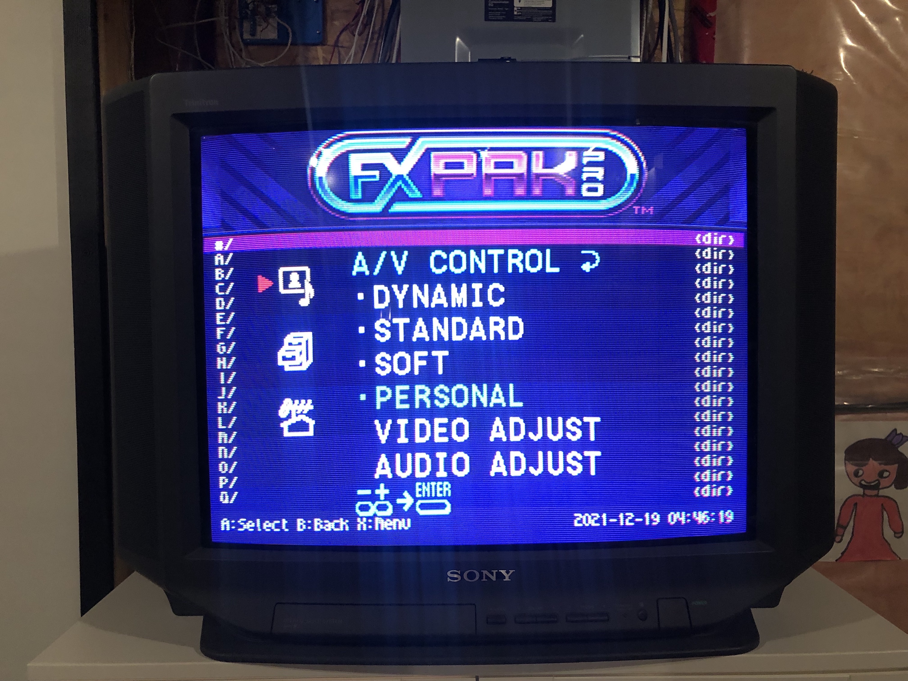
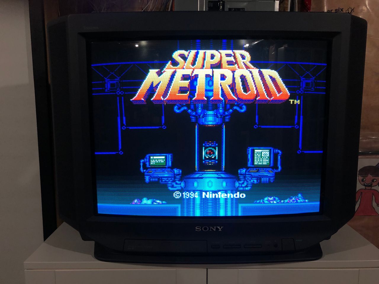
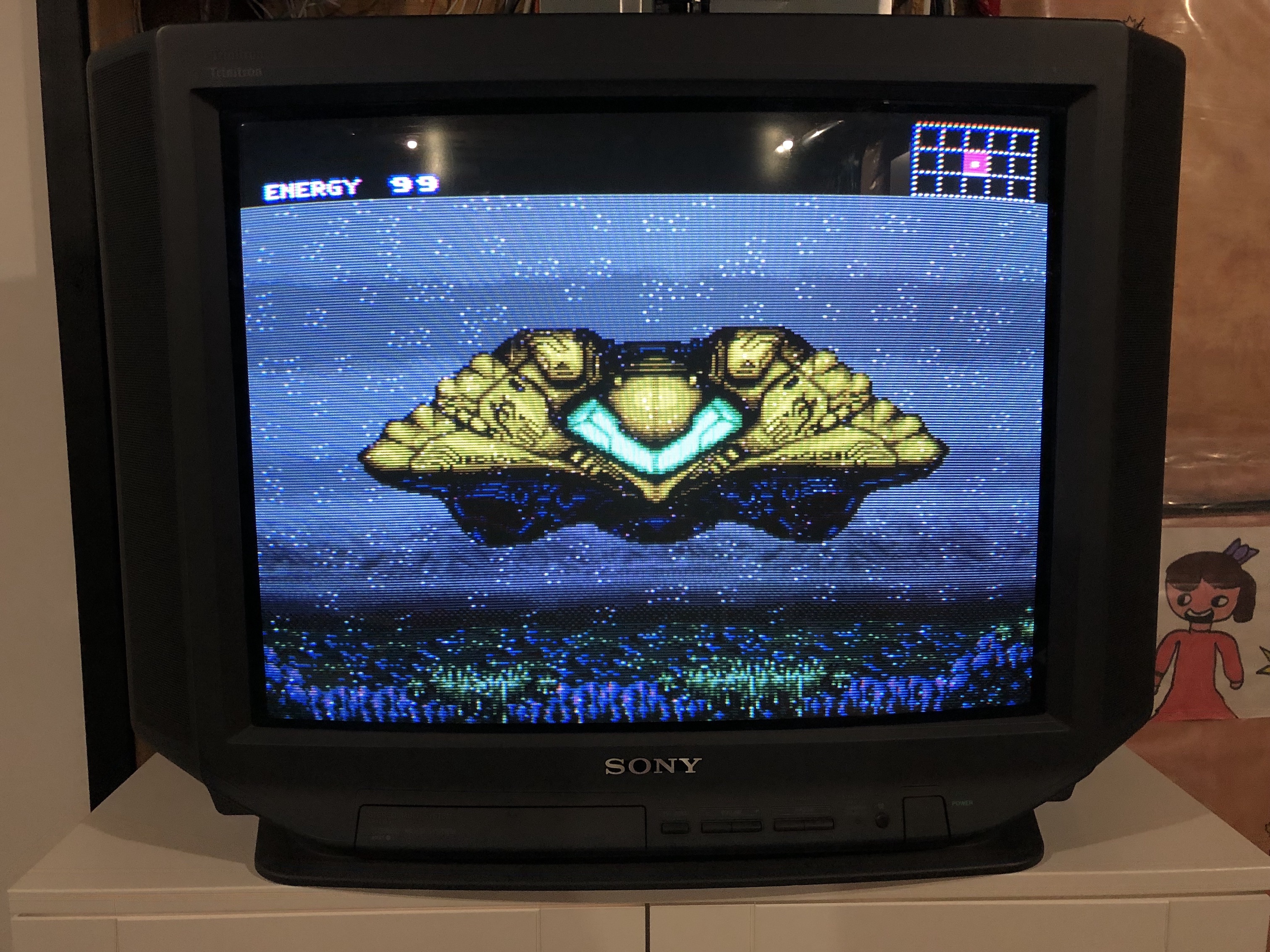
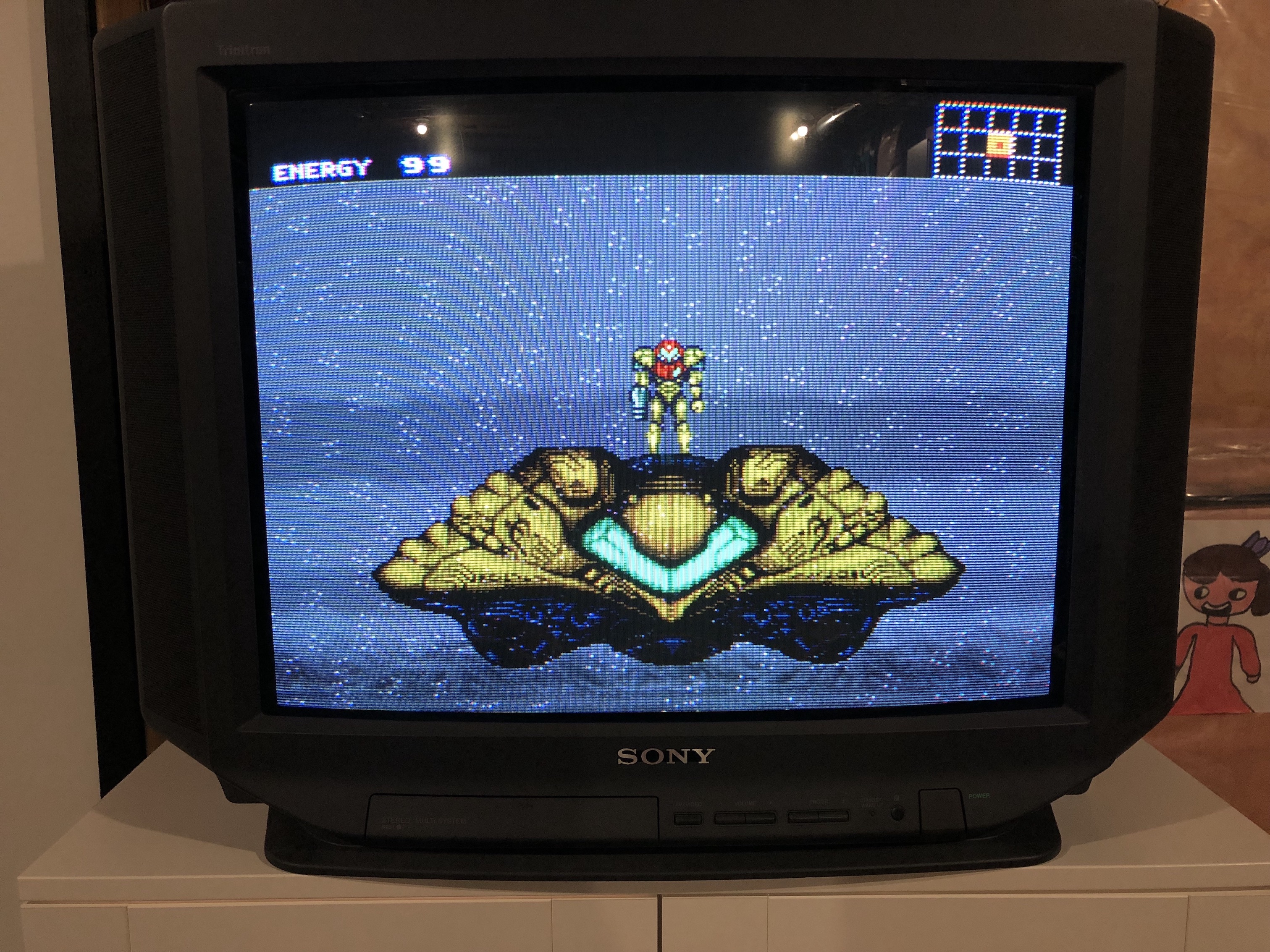
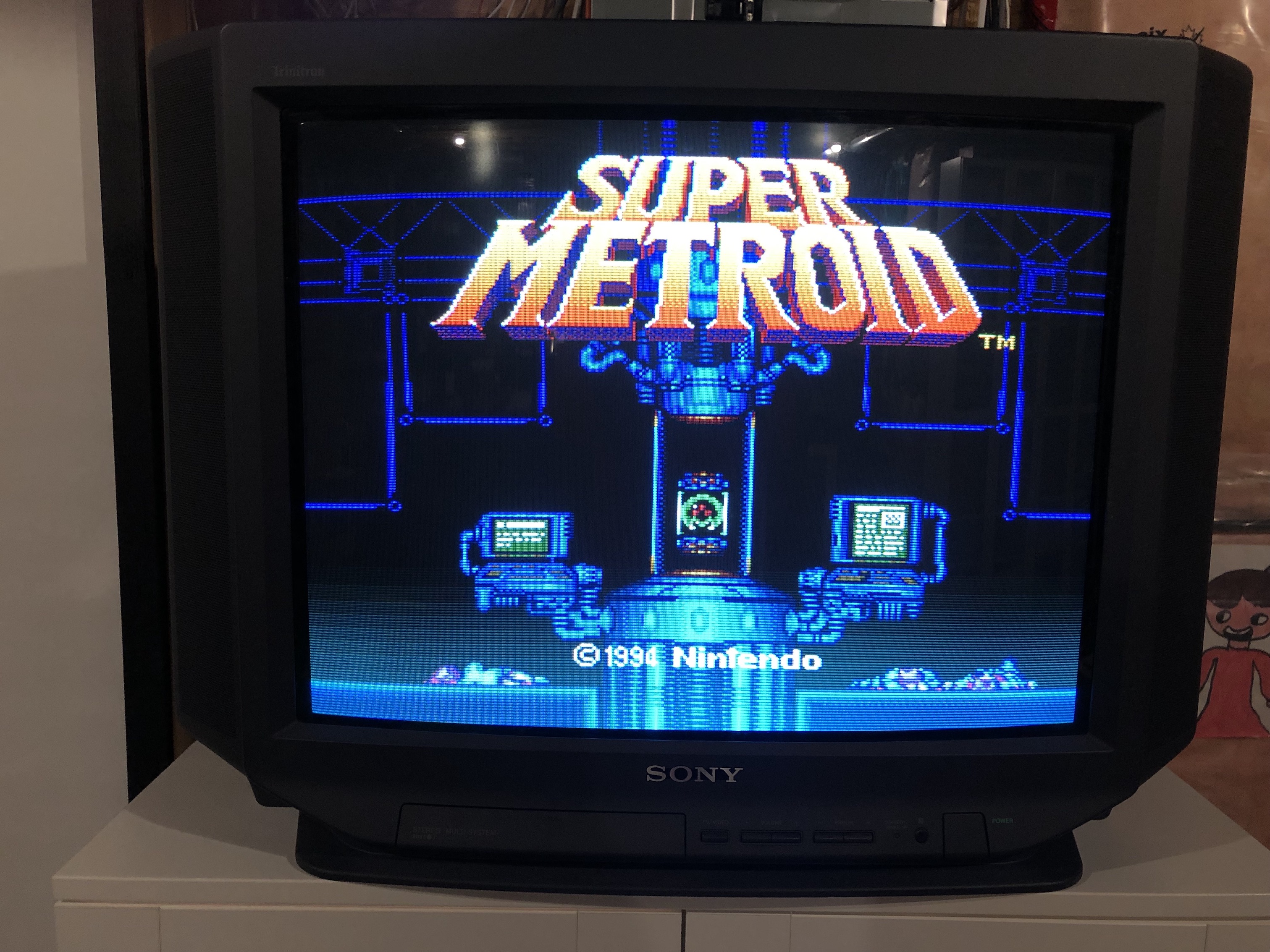
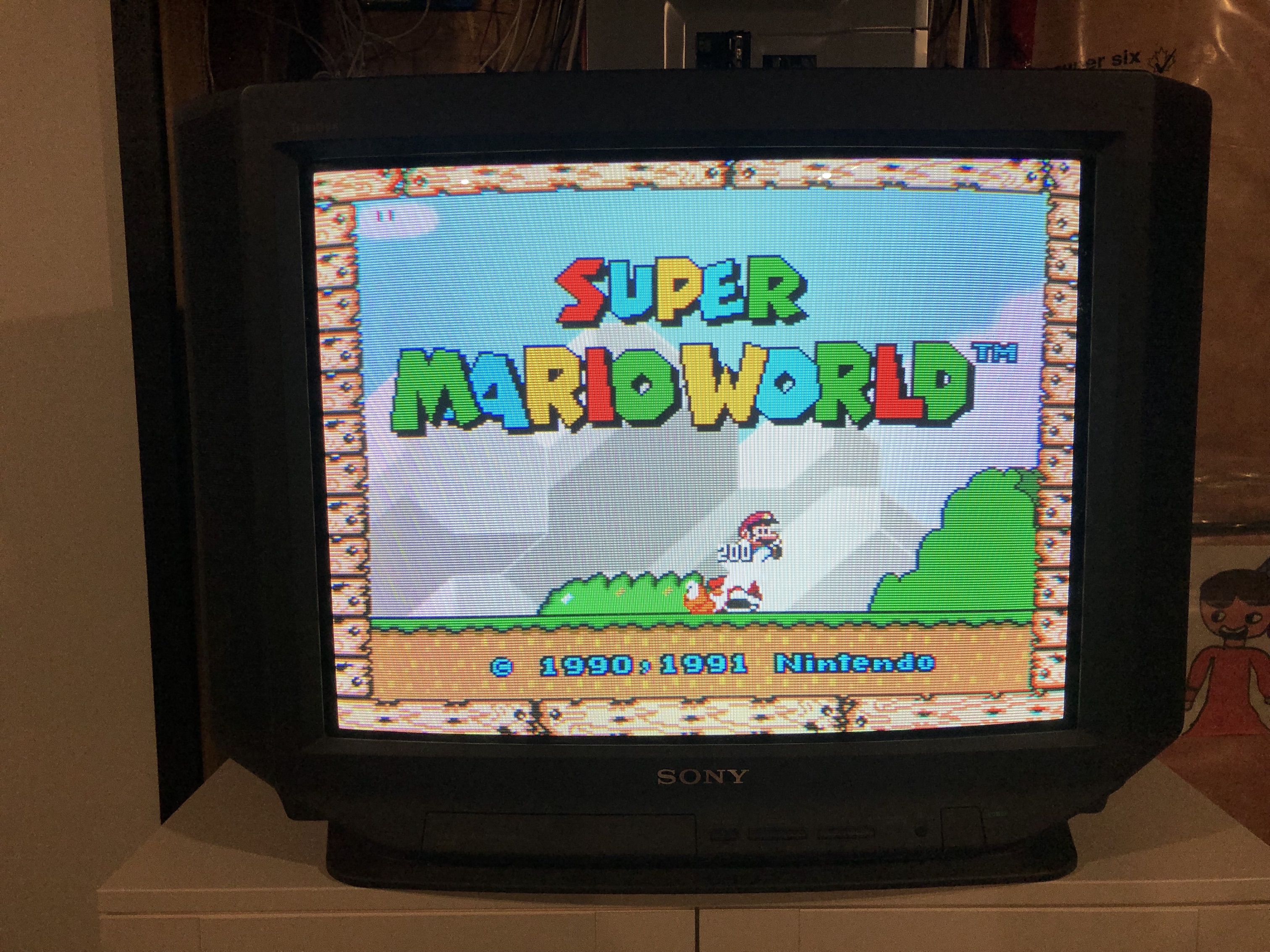
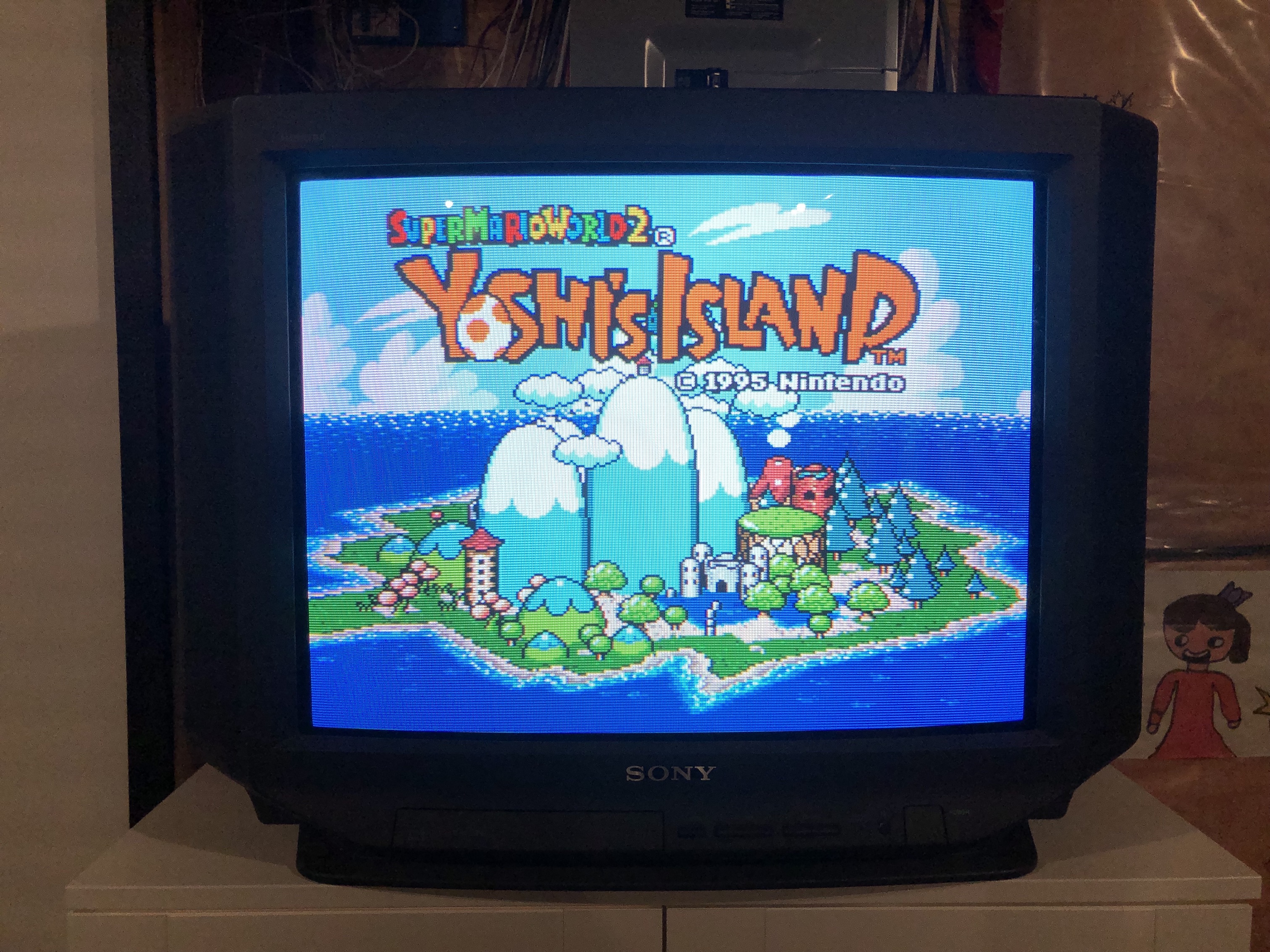
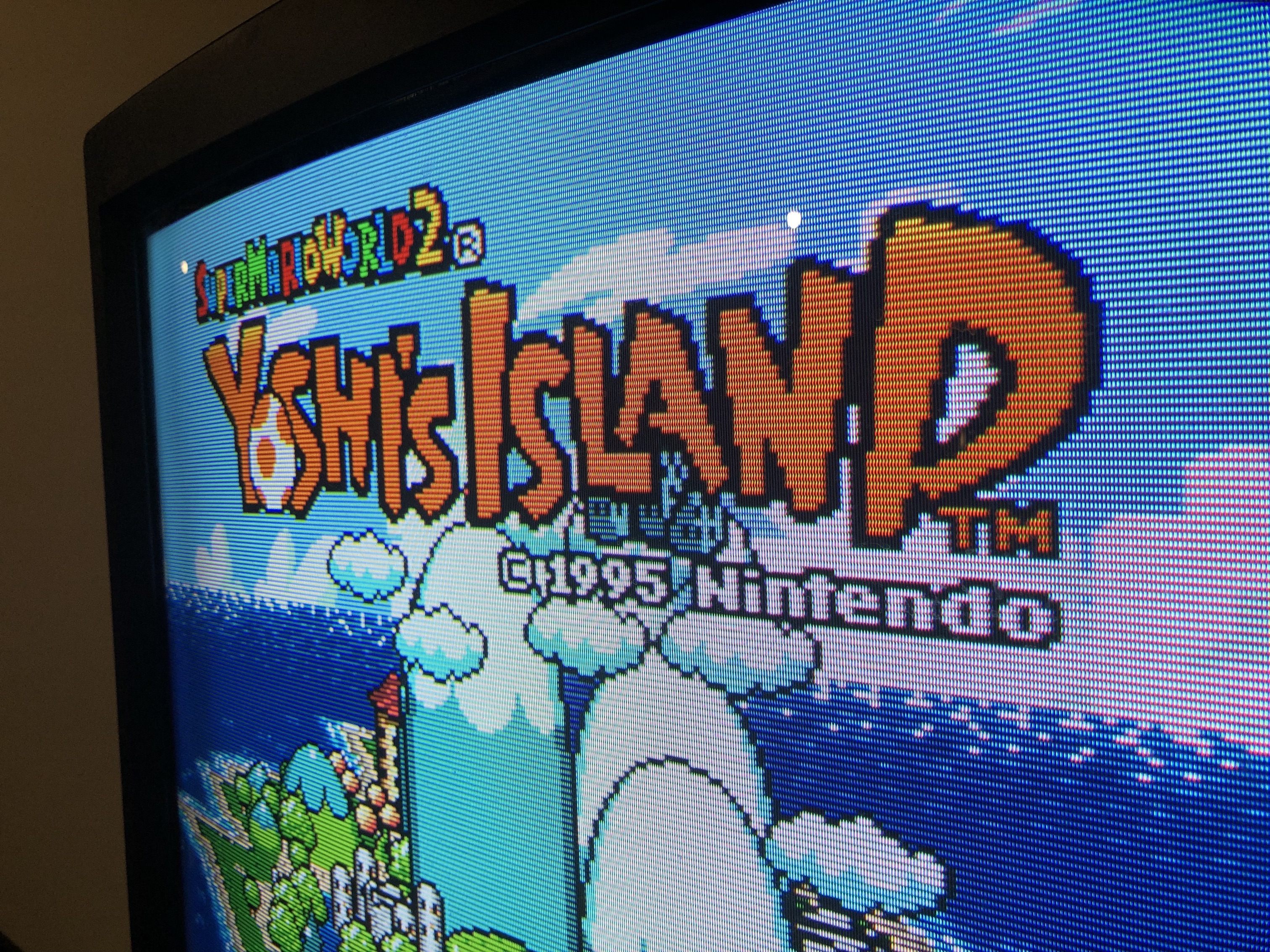
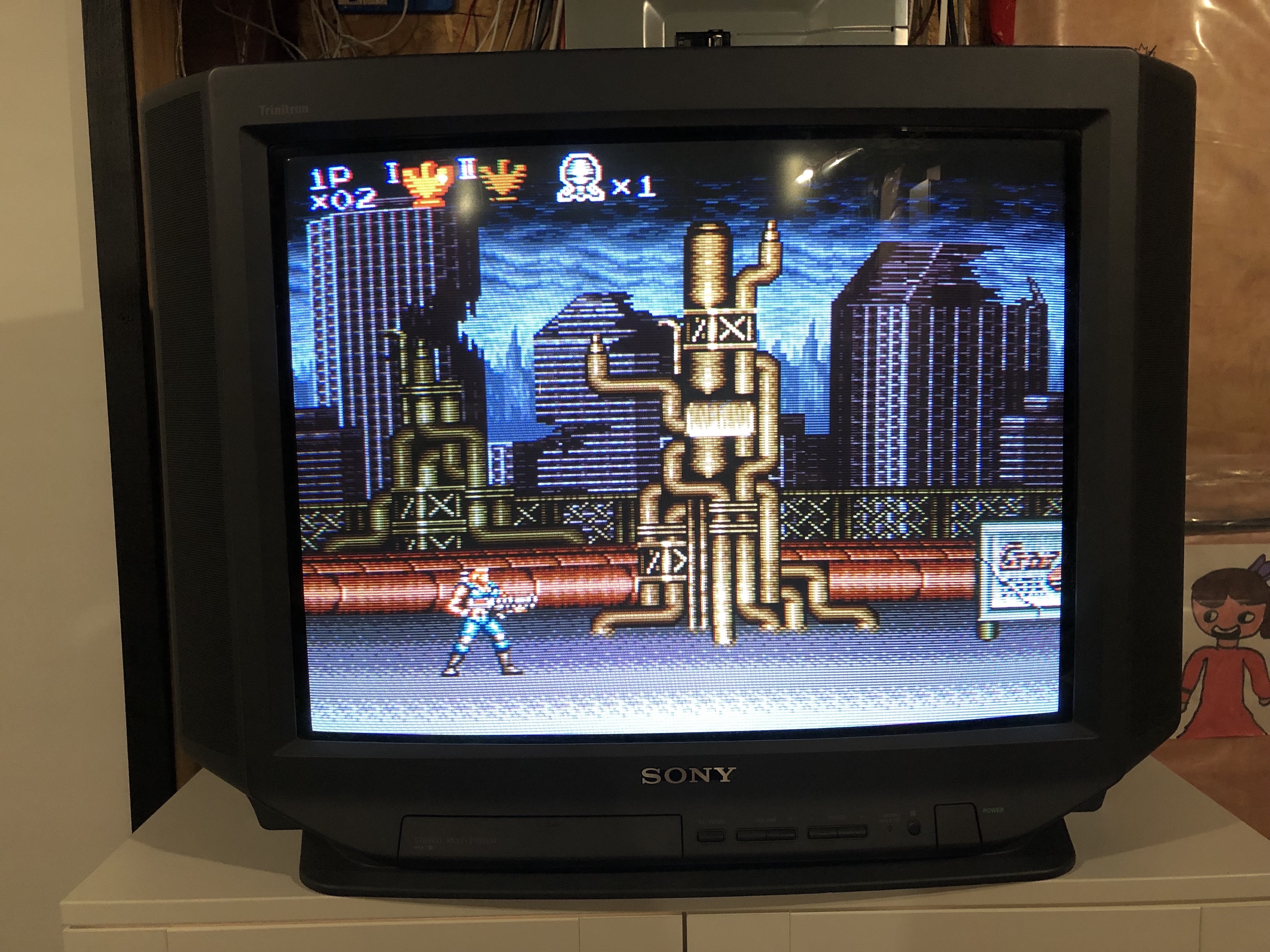
Games
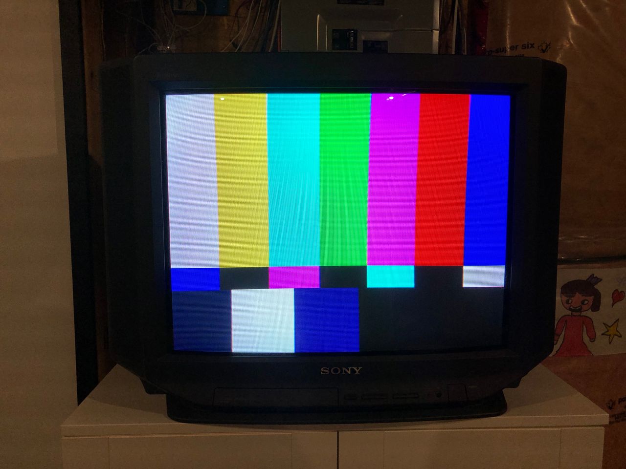
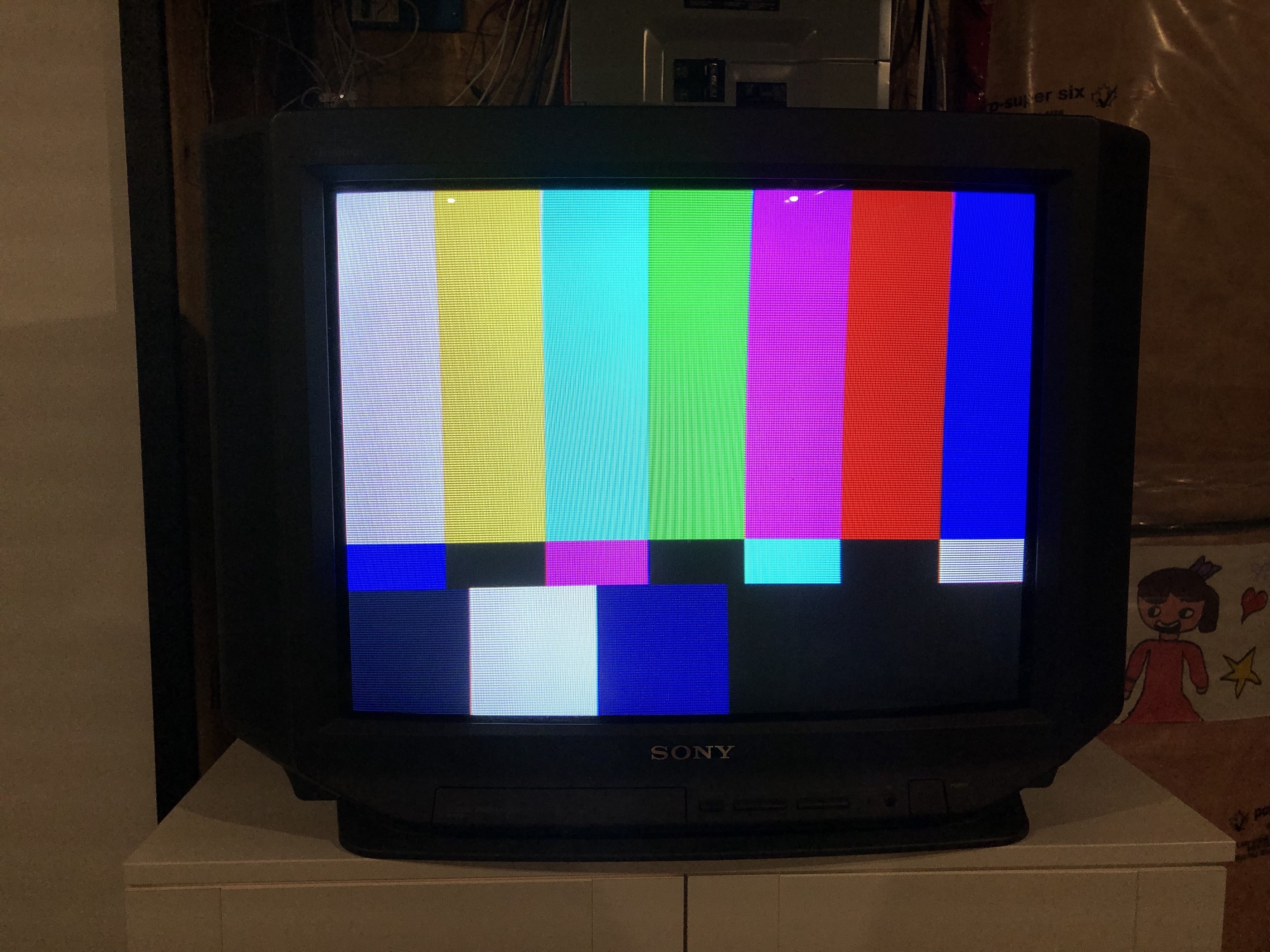
Patterns
Set
Tube 
Back open 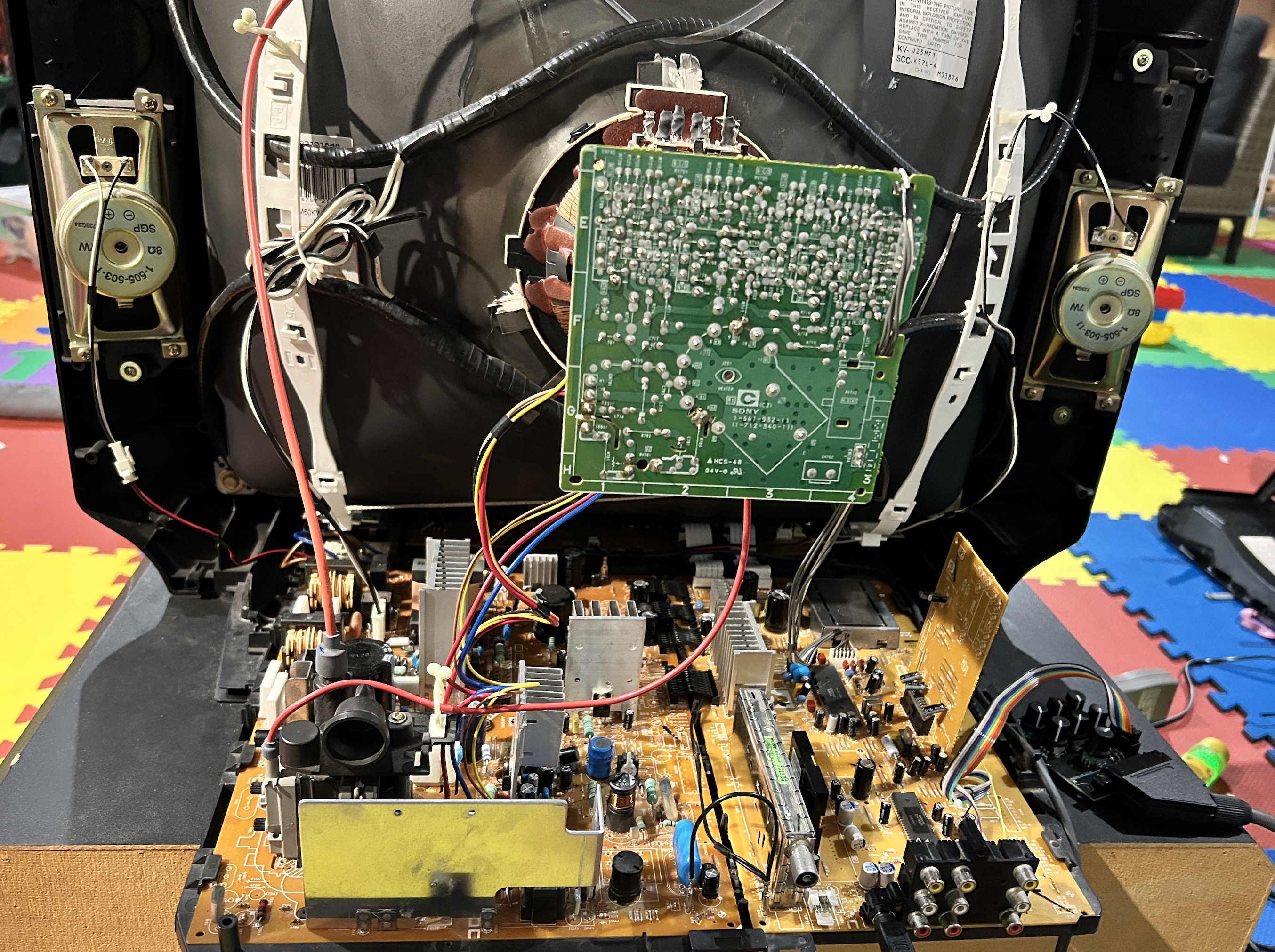
Back Label 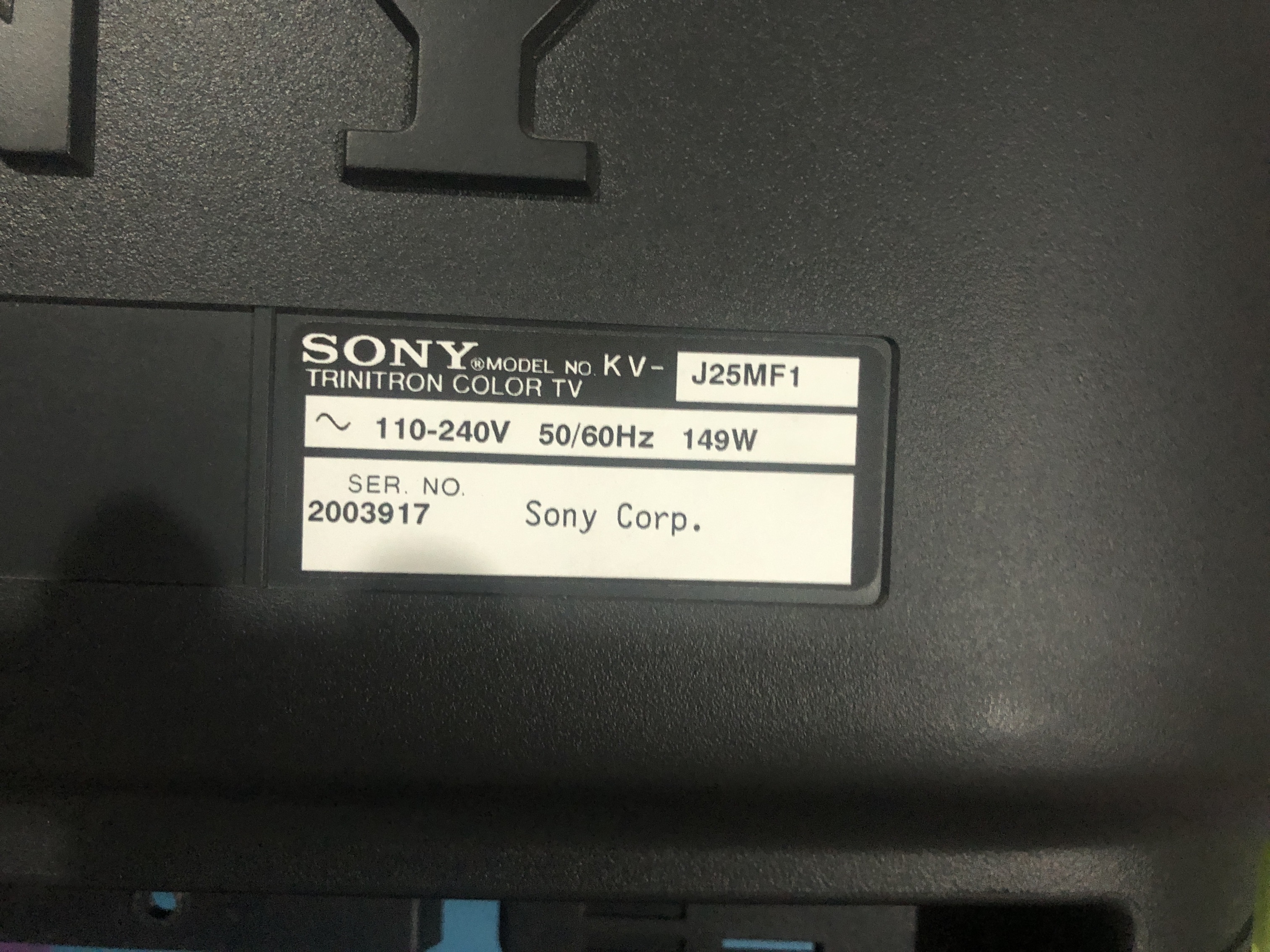
Neck Board 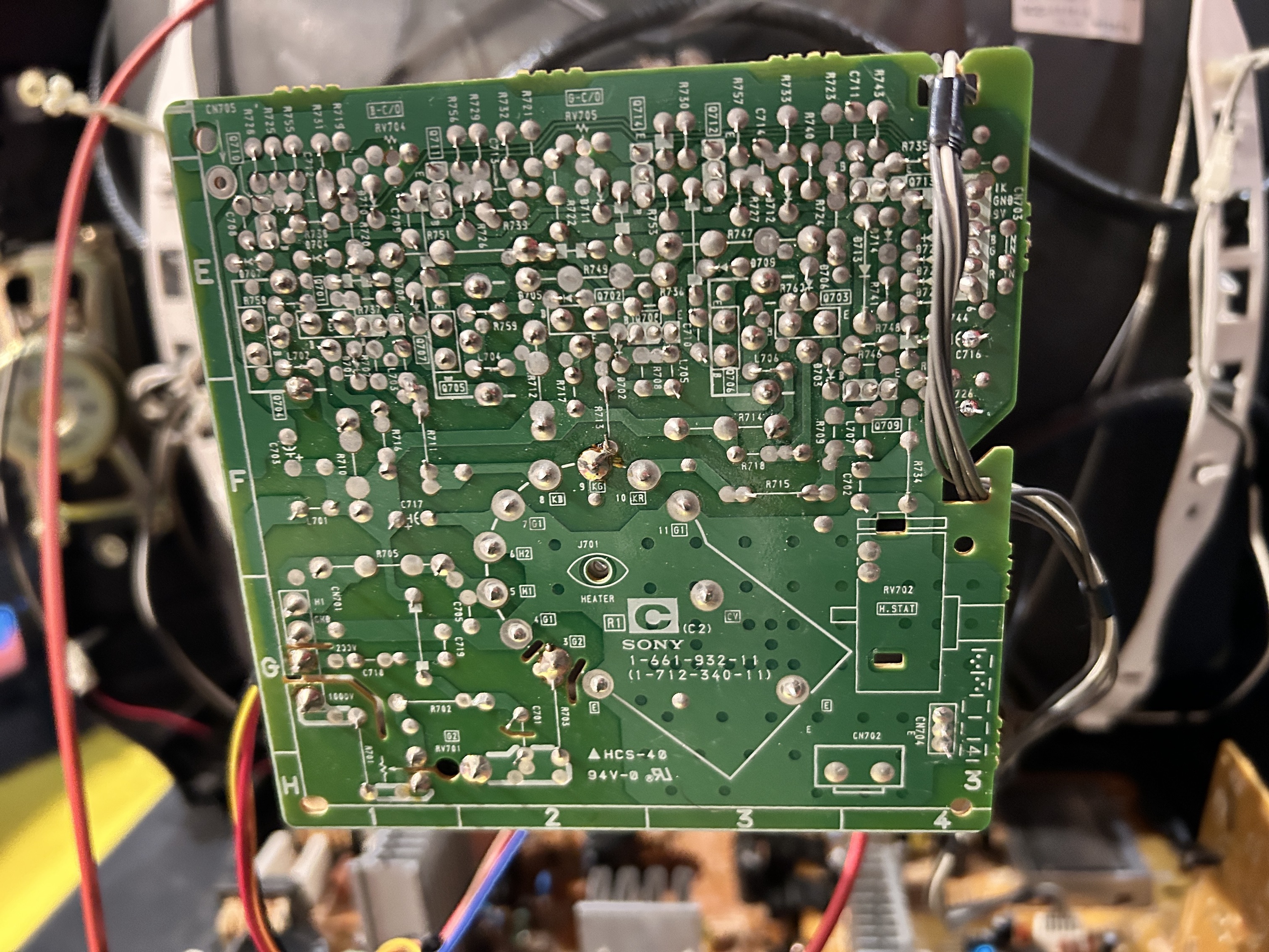
Pictures
Reference Photos