
Soldering 101 for CRT
CRT is no place to practice your soldering skills. These boards are 20 to 40 years old, the pads lift if you linger, and a bad joint on an RGB line will haunt you later. That said, soldering wires onto a chassis is most of the RGB mod. Here is what I actually use, and how I do it.
Tools needed
You do not need a $400 station. You do need the right few pieces.
- Solder — 0.6mm, 63/37 Sn/Pb
- Temperature-controlled soldering iron
- Wire stripper rated for 22 AWG to 32 AWG (so you can strip to the exact spec)
- Fume extractor
- Desoldering tool (nice to have)
- Mask
- Gloves
WASH YOUR HANDS
Make sure to wash your hands after you are done with the soldering job. Leaded solder is not something you want on a sandwich.
Also read CRT safety before you even pick up the iron around an open set.
Soldering iron
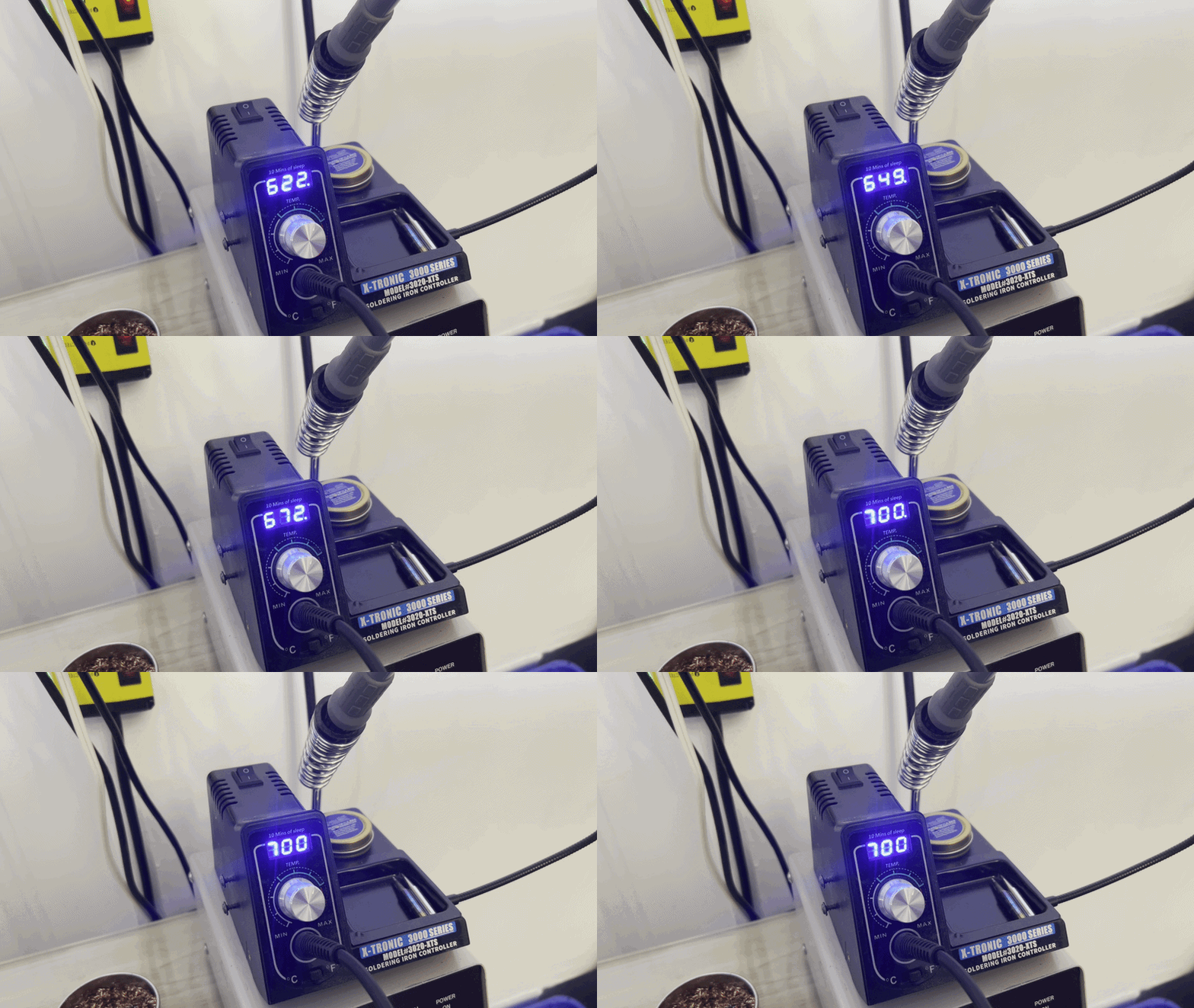
I don't have anything fancy here. This $80 soldering tool became my complete companion once paired with a Hakko tip. Set the iron to 700 °F (or 370 °C).
Let's begin our Soldering 101 journey. Nothing fancy. The right tip matters more than the brand on the handle.
The right solder
I have tried many different solders, but this leaded solder is inarguably the best. At 0.6mm, the thin wire and 2.0% flux simply melt and make the soldering experience a breeze. The lead flows incredibly smoothly and forms a strong bond at lower heat. Your traces are safer, and the finished job looks clean and professional.
I'm not in any way associated with SainSmart. As long as your solder meets this specification, you should be good. I put some trust in this one because the company is based in the USA and, assuming they have good quality standards, the roll is consistent.
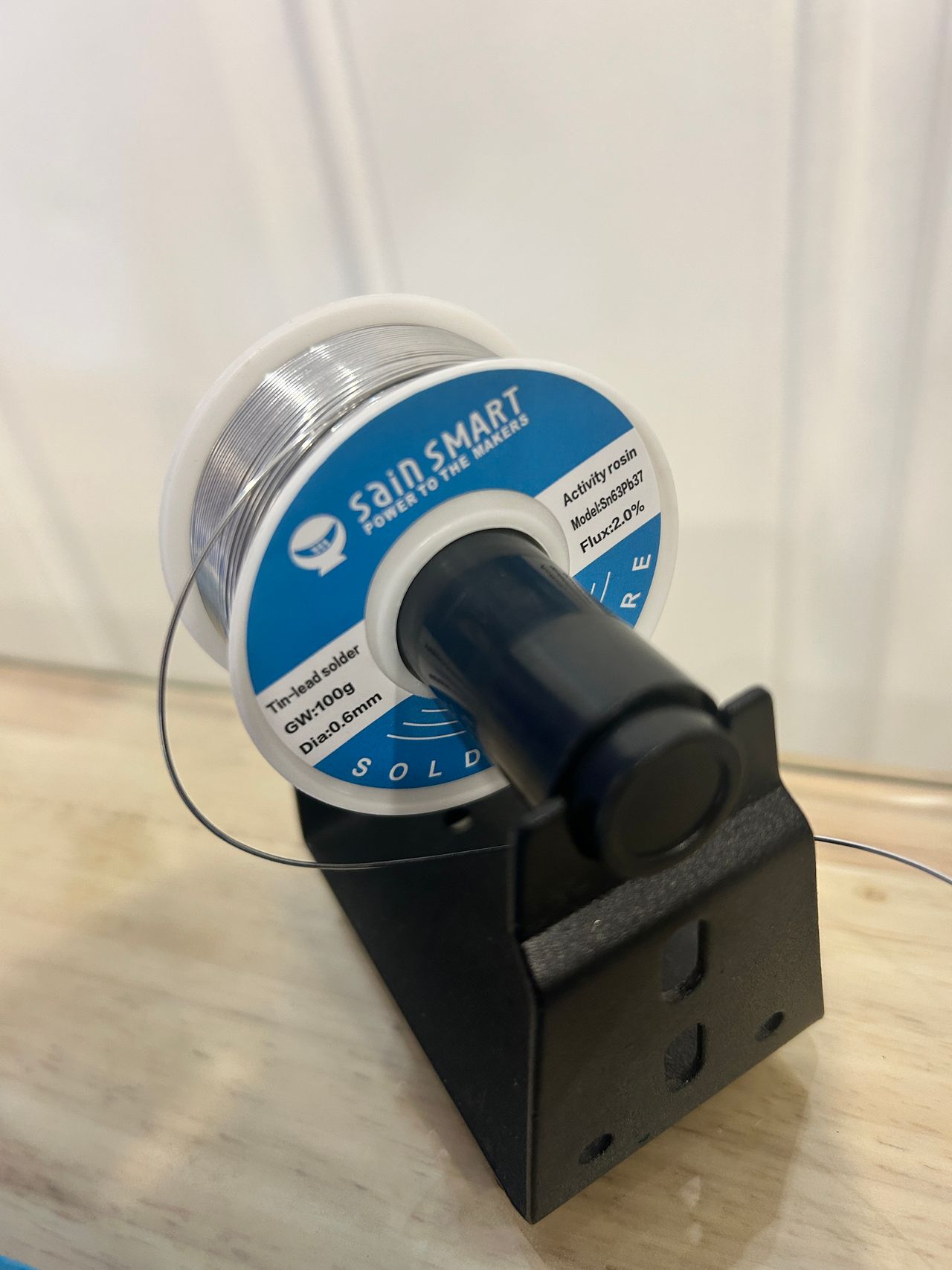 0.6mm, 63/37 Sn/Pb, 2.0% rosin core. This is the stuff.
Specs
- Diameter: 0.6mm
- Tin/Lead composition: 63/37
- Flux: 2.0% rosin core
With this solder, you don't need any extra flux. If you have to add flux, you are doing something wrong.
ROSIN FLUX
Don't use extra rosin flux if you can help it. Rosin residue on a CRT board can cause interference. See Plan of attack.
Fume extractor
Make sure you have a fume extractor nearby. Positioning it close to your soldering area helps pull the fumes away from you instead of letting them drift toward your nose.
See that white stuff? That's flux smoke that could have otherwise ended up in your breathing zone.
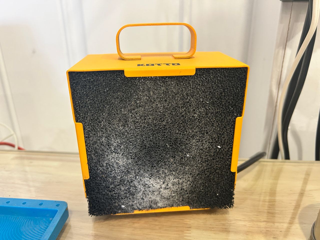 Park the extractor right next to the joint. You want the smoke going into the filter, not into you.
Warning
When it comes to safety, always take care of yourself, whether you're working on a small repair or a large project. Your health is worth the extra effort. After all, you want to outlast your CRT!
Preparing the wires
If you have a ribbon cable, separate the strands first.
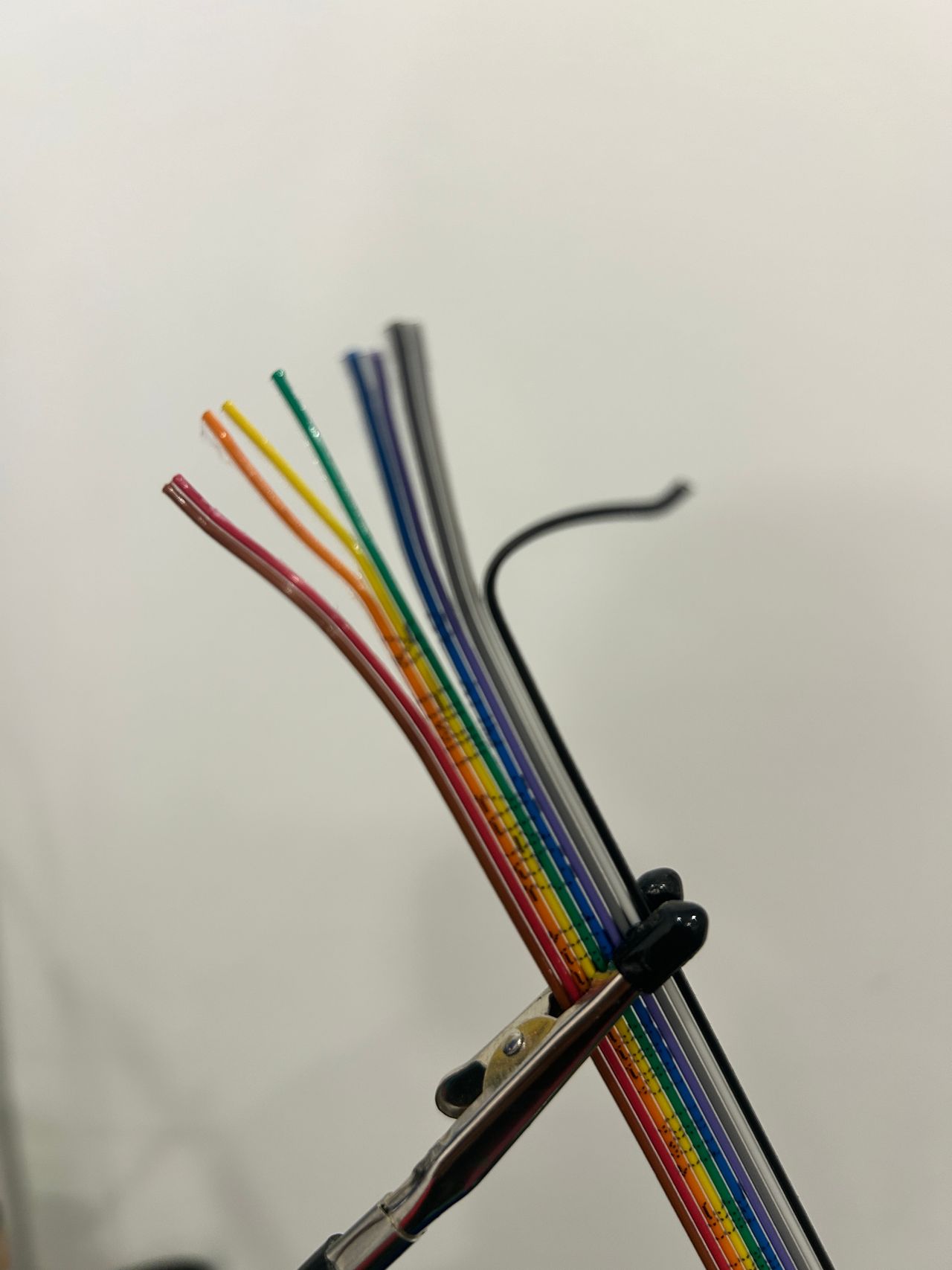 Peel the ribbon so each conductor can be stripped and tinned on its own.
Use a proper wire stripper rated for 26 AWG 3M ribbon cable.
So, why use a wire stripper? I have sharp nails and teeth, why don't I put them to use?
You want to preserve every strand of the wire. A proper stripper removes the insulation cleanly without nicking or cutting the individual strands. Damaging the strands reduces the wire's effective conductivity and can lead to unreliable connections — something you definitely don't want when working with RGB signals.
Also, you don't want to chew on plastics and lead.
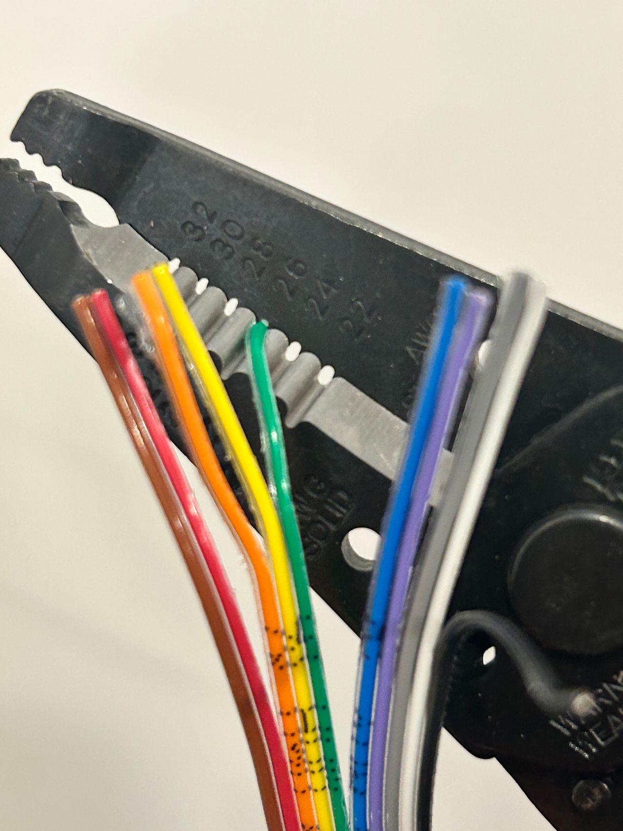 Use a stripper that actually matches the gauge. Nails and teeth are not a process.
Showing green wire as an example. Strip no more than 3mm of insulation for optimal results.
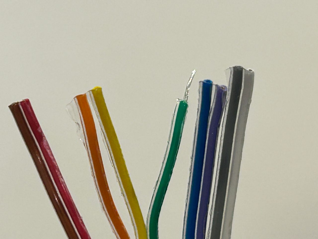 3mm of bare copper is plenty. More than that just gives you a sloppy joint and extra lead to clip.
Tin the wire
Tin the stripped end so the strands become one solid tip.
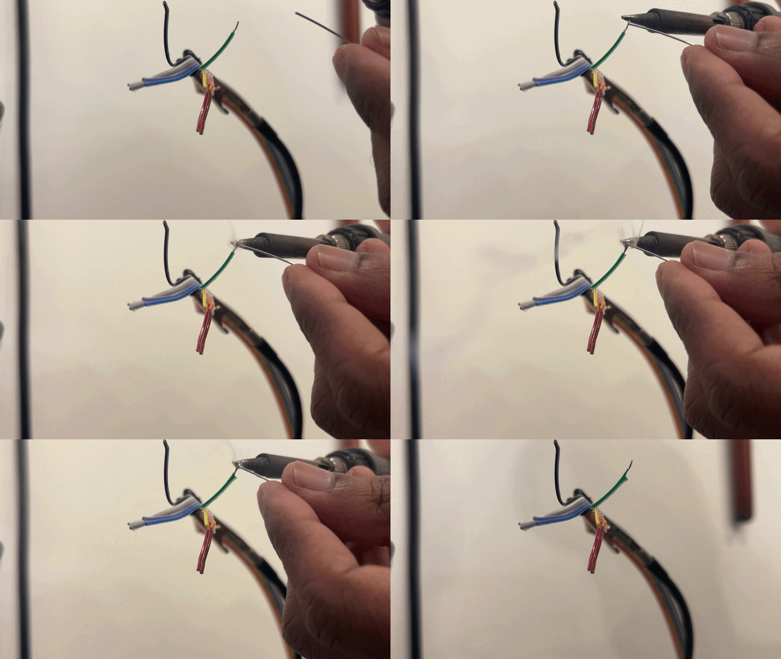 Heat the wire, feed a little solder, and get out. You want a shiny tip, not a blob.
Just leave about 1mm to 2mm of tinned wire and clip the rest.
Carefully dispose of the leaded leftover.
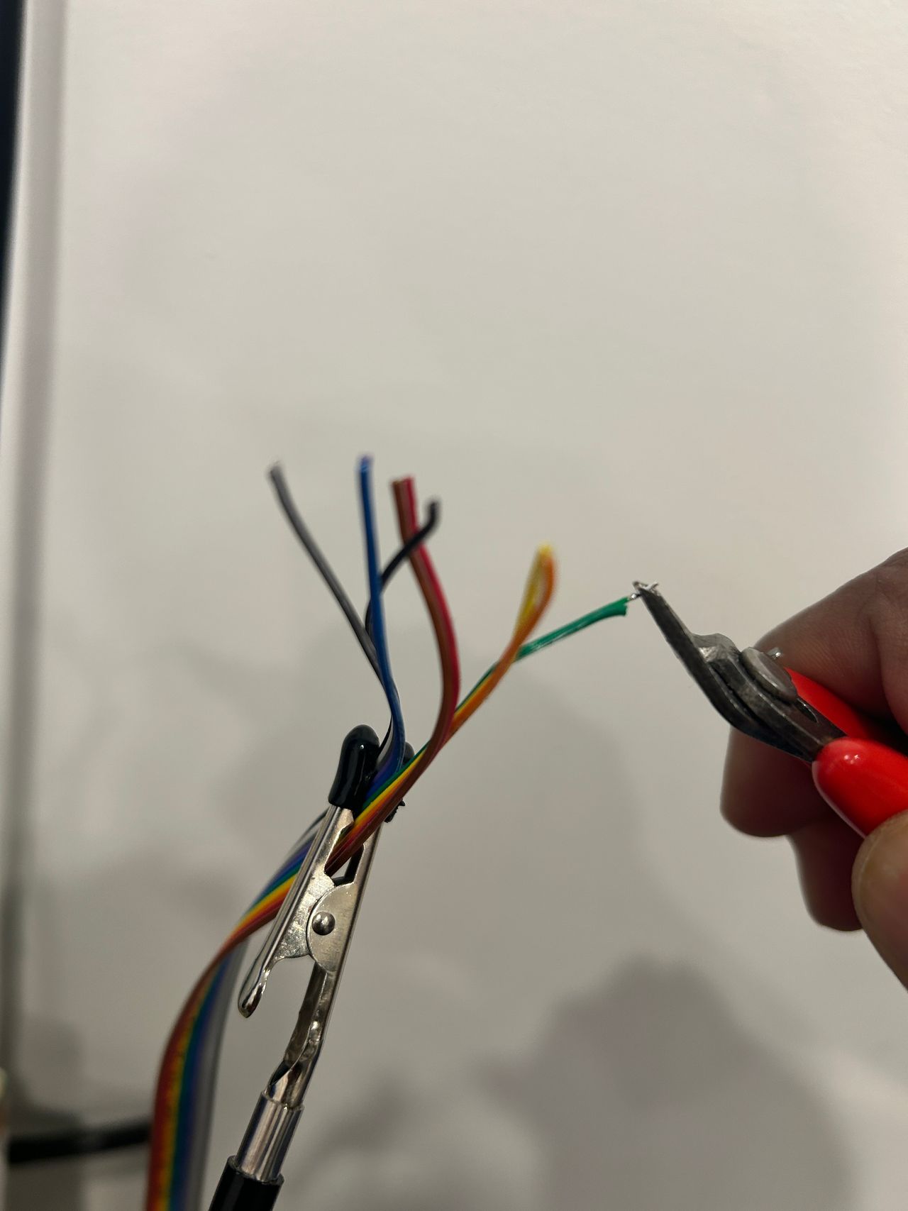 Short tinned tip. Clip the excess and treat the scraps like the lead they are.
Green is ready to go. Do the same for the other wires. Sometimes you need different lengths based on where they are getting soldered, so cut first and keep the runs as short as you can.
Make sure:
- R, G, B wires are of equal lengths
- Audio Left and Audio Right wires are of equal lengths
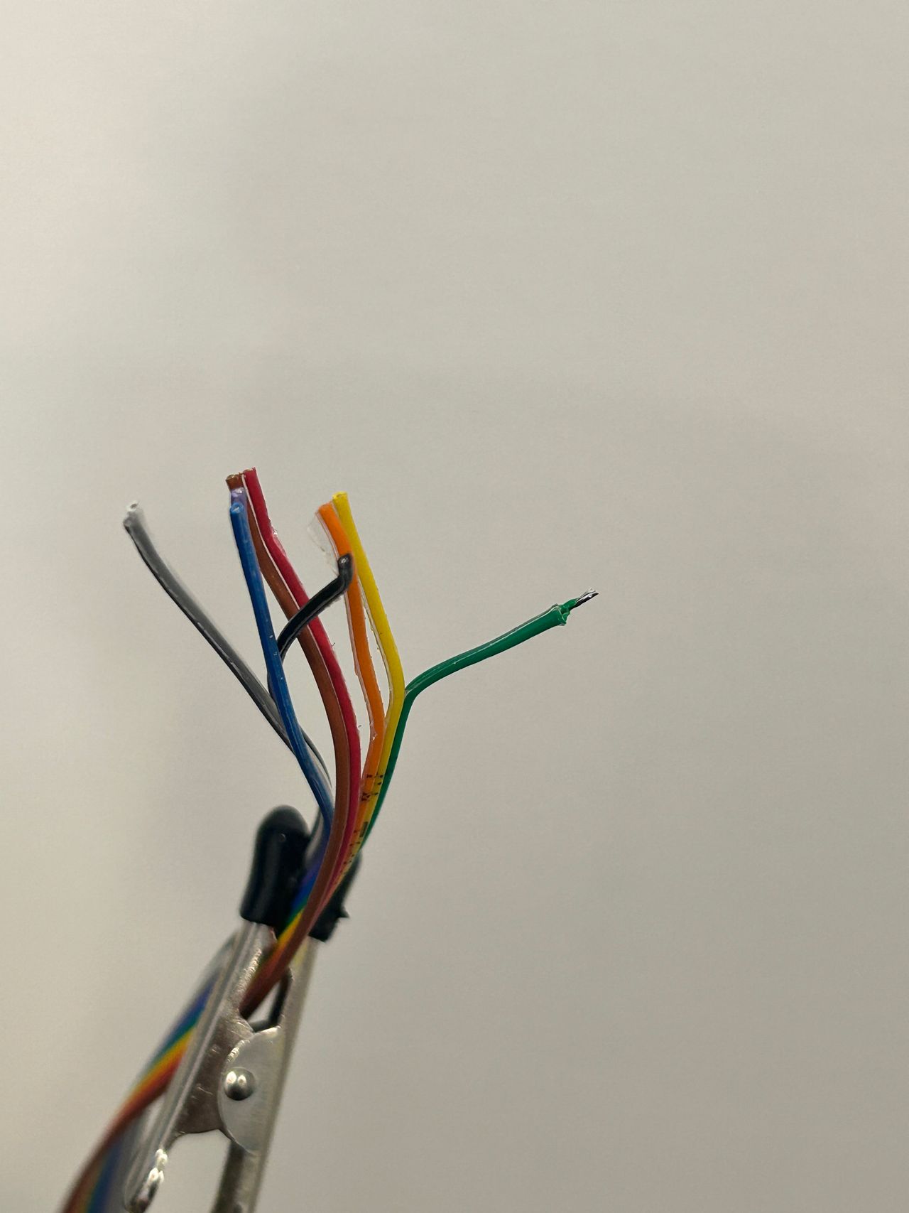 One wire done. Match RGB lengths to each other, and match the two audio wires to each other.
Soldering to the chassis
Tin the pad on the chassis first. I'd usually hold the solder with my hand and do this, but I'm using my other hand to film this. You get the idea.
Also, keep in mind that these CRT PCBs are now 20 to 40 years old. Nothing lasts forever, and PCBs are no exception. Decades of heat, cooling cycles, and previous repairs can make the copper traces and solder pads more susceptible to lifting. Be especially careful when soldering on older boards. Excessive heat or mechanical force can cause a trace or pad to separate from the PCB.
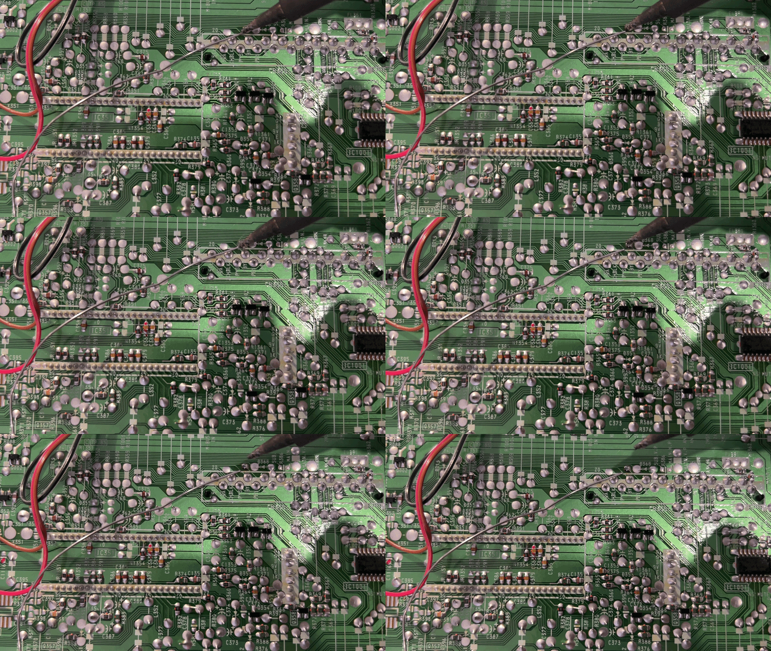 Tin the pad, then get off it. Old copper does not forgive a lingering iron.
OLD PADS LIFT
These chassis are brittle from age. If a pad starts to lift, stop. Do not pry, do not reheat it hoping it will settle, and do not yank the wire. Find another legitimate pad or via on that same net.
Place the tinned wire against the tinned pad. Touch with your soldering iron for no more than a second. These two joints should just fuse.
That's it. No flux, no fuss!
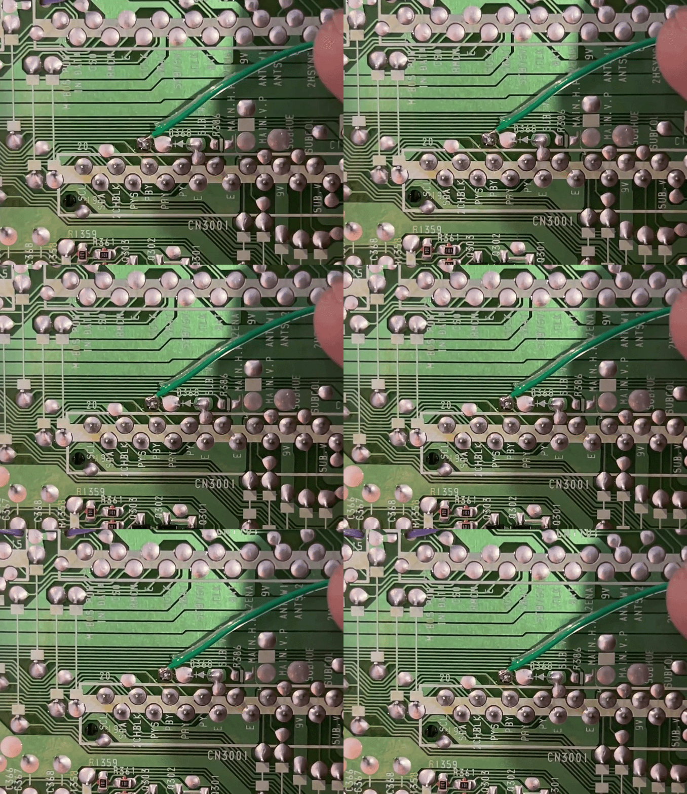 Pad is tinned, wire is tinned, one second of heat. If it does not wet immediately, you are too cold, too dirty, or lingering too long.
That's it
A good CRT solder joint is small, shiny, and done quickly. If you are fighting the joint, something is wrong — wrong temperature, wrong solder, or a pad that has already had enough of this hobby.
Once the wires are on, get back to the plan of attack and do your continuity checks before you apply power.